EP0601748A1 - Maschine zum Kantenscheifen von Halbleiterplatten - Google Patents
Maschine zum Kantenscheifen von Halbleiterplatten Download PDFInfo
- Publication number
- EP0601748A1 EP0601748A1 EP93309445A EP93309445A EP0601748A1 EP 0601748 A1 EP0601748 A1 EP 0601748A1 EP 93309445 A EP93309445 A EP 93309445A EP 93309445 A EP93309445 A EP 93309445A EP 0601748 A1 EP0601748 A1 EP 0601748A1
- Authority
- EP
- European Patent Office
- Prior art keywords
- wafer
- buff
- edge
- arm
- framework
- Prior art date
- Legal status (The legal status is an assumption and is not a legal conclusion. Google has not performed a legal analysis and makes no representation as to the accuracy of the status listed.)
- Granted
Links
Images





Classifications
-
- B—PERFORMING OPERATIONS; TRANSPORTING
- B24—GRINDING; POLISHING
- B24B—MACHINES, DEVICES, OR PROCESSES FOR GRINDING OR POLISHING; DRESSING OR CONDITIONING OF ABRADING SURFACES; FEEDING OF GRINDING, POLISHING, OR LAPPING AGENTS
- B24B9/00—Machines or devices designed for grinding edges or bevels on work or for removing burrs; Accessories therefor
- B24B9/02—Machines or devices designed for grinding edges or bevels on work or for removing burrs; Accessories therefor characterised by a special design with respect to properties of materials specific to articles to be ground
- B24B9/06—Machines or devices designed for grinding edges or bevels on work or for removing burrs; Accessories therefor characterised by a special design with respect to properties of materials specific to articles to be ground of non-metallic inorganic material, e.g. stone, ceramics, porcelain
- B24B9/065—Machines or devices designed for grinding edges or bevels on work or for removing burrs; Accessories therefor characterised by a special design with respect to properties of materials specific to articles to be ground of non-metallic inorganic material, e.g. stone, ceramics, porcelain of thin, brittle parts, e.g. semiconductors, wafers
-
- B—PERFORMING OPERATIONS; TRANSPORTING
- B24—GRINDING; POLISHING
- B24B—MACHINES, DEVICES, OR PROCESSES FOR GRINDING OR POLISHING; DRESSING OR CONDITIONING OF ABRADING SURFACES; FEEDING OF GRINDING, POLISHING, OR LAPPING AGENTS
- B24B49/00—Measuring or gauging equipment for controlling the feed movement of the grinding tool or work; Arrangements of indicating or measuring equipment, e.g. for indicating the start of the grinding operation
- B24B49/16—Measuring or gauging equipment for controlling the feed movement of the grinding tool or work; Arrangements of indicating or measuring equipment, e.g. for indicating the start of the grinding operation taking regard of the load
Definitions
- the present invention relates to an apparatus for bevelling the edge of a semiconductor wafer (hereinafter, referred to as a wafer) by polishing.
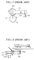
- FIG.17 is a plan view of a main structure of a prior-art wafer edge bevelling machine.
- the main structure of the prior-art wafer edge bevelling machine comprises an arm 101 an intermediate of which is mounted on a pivot 102, a cylindrical buff 103 rotatably mounted to an end of the arm 101, an air cylinder assembly 109 having a piston rod in contact with the side of the other end of the arm 101 for pushing the buff 103 against the edge of a wafer W, and a suction turntable 110 positioned near the buff 103 and sucking the wafer W in place.
- a driver (not shown) rotates the buff 103 at a high speed counterclockwise in FIG.17, the air cylinder assembly 109 concurrently pushes the other end of the arm 101 by a fixed force F in the direction of an arrow F, and the suction turntable 110 is rotated at a low speed counterclockwise in FIG.17.
- the buff 103 is pressed on the edge of the wafer W by a contact pressure a and edge the edge of the wafer W is edged.
- the contact pressures ⁇ 1, ⁇ 2 and ⁇ 3 produced on the orientation flat W1, the circular edge W2 and the round joints W3 are reduced in response to the radii of curvature R1, R2 and R3 (i.e., ⁇ 1 ⁇ 2 ⁇ 3).
- the round joints W3 receive an excessive contact pressure so that the edges of the round joints W3 may have an abnormally strong grip on the buff 103 to abnormally polish or bevel the round joints W3.
- the force F of the air cylinder assembly 109 must be so small that the round joints W3 will not have the abnormally strong grip on the buff 103. This reduces the productivity in the wafer edge bevelling.
- the prior-art wafer edge bevelling machine cannot have an optimal uniform finish precision over the edge of the wafer W.
- the buff 103 is removed from the wafer edge bevelling machine and then worked by a dedicated lathe to provide a new formed groove 103a. It is a second method that as shown in FIG.18 a rotating shaft 110R of the wafer suction turntable 110 has a radially extending cutter 131 normally installed thereon and the cutter 131 is vertically moved and produces the formed groove 103a in the buff 103, if necessary.
- the attachment and the detachment of the buff 103 to and from the wafer edge bevelling machine are troublesome and the installation precision of the buff 103 to the wafer edge bevelling machine is problem.
- the wafer edge bevelling machine produces the formed groove 103a while the rotating shaft 130 has the buff 103 normally installed thereon, so that the installation precision of the buff 103 on the rotating shaft 130 is not problem.
- the cutter 131 is normally exposed to a slurry 113 containing a polishing material during wafer edge bevelling because of the normal installation of the cutter 131 on the rotating shaft 130, so that the cutter 131 must be made of a special protective material, e.g. an expensive and difficultly available ceramic material. Therefore, the kinds of available cutters are restricted.
- an apparatus comprises: a framework; a table rotatably mounted on the framework and capable of holding the wafer; a buff rotatably mounted on the framework opposite the table and having a formed groove for bevelling the edge of the wafer; pressing means mounted on the framework, for pressing the buff on to the edge of the wafer; a sensor for sensing at least the orientation flat of the wafer held on the table and producing a corresponding signal to indicate the orientation of the wafer; and, a control means controlling the pressing means to apply different forces between the buff and the wafer in the region of its orientation flat, its circular edge and its round joints.
- the apparatus in accordance with this invention provides an optimal bevelling precision over the wafer edge, and increases the productivity in the wafer edge bevelling operation.
- the forces may comprise a first force by which the pressing means presses the buff on the orientation flat, a second force by which the pressing means presses the buff on the circular edge, and a third force by which the pressing means presses the buff on the round joints.
- the first, second and third forces have such a relation that the first force is largest, the second force is intermediate and the third force is smallest.
- the pressing means may comprise an air cylinder assembly
- the control means may comprise a pneumatic control circuit and an electronic central processing unit.
- the pneumatic control circuit comprises a compressed air source and a solenoid operated valve.
- the solenoid operated valve changes the pressure of compressed air supplied from the compressed air source to the air cylinder assembly into three different pressures in response to the forces under the control of the electronic central processing unit.
- the senor may comprise a photo-sensor having a light emitting element and a light receiving element arranged opposite each other through the wafer held by the table.
- the photo-sensor is positioned relative to the table so that the area of a cross section of a beam of light received by the light receiving element is largest when the centre of the orientation flat passes through a beam of light emitted from the light emitting element.
- the signals have voltages proportional to the area.
- control may determine the forces to produce substantially the same contact pressure on a point of bevelling between the edge surface of the formed groove and the edge of the wafer over the edge of the wafer.
- the apparatus uniformly bevels the orientation flat, the circular edge and the round joints by the substantially equal contact pressures and ensures an optimal wafer edge bevelling precision over the wafer edge to increase the productivity in the bevelling.
- an apparatus comprises: a framework; an arm, an intermediate portion of which is pivotally mounted on the framework; a table rotatably mounted on one end of the arm and capable of holding the wafer; a buff rotatably mounted on the framework opposite the table and having a formed groove for bevelling the edge of the wafer; a pusher for pushing the other end of the arm in a direction of the rotation of the arm in which the one end of the arm approaches the buff; a grooving cutter assembly capable of being removably held by the table and of producing the formed groove; a lock preventing rotation of the table when the grooving cutter assembly produces the formed groove; and, a stopper mounted on the framework and stopping the rotation of the arm, the stopper positioning the grooving cutter assembly relative to the buff in co-operation with the pusher.
- This aspect of the present invention provides an apparatus for easily and precisely producing a formed groove in the buff for bevelling the wafer edge, which does not degrade the installation precision of the buff and requires no measure for taking account of the polishing slurry.
- the apparatus may further comprise a return spring urging the arm in a direction of the rotation of the arm in which the wafer held by the table is moved away from the buff.
- the pusher may comprise an air cylinder assembly having a piston rod in contact with the other end of the arm.
- the stopper may be opposite the pusher through the arm and movable in the direction of the piston rod. The stopper produces a counterforce having a direction in alignment with the direction of a push of the piston rod.
- the apparatus may further comprise the pusher pushing the arm by different forces to cause the buff to press by substantially the same contact pressure the orientation flat, the circular edge and the round joints of the wafer held down by the table, a sensor sensing the orientation flat, the circular edge and the round joints of the wafer held down by the table and producing corresponding signals, and a control controlling the pusher to select between the forces in response to the signals.
- the forces may comprise a first force by which the arm presses the buff on the orientation flat, a second force by which the arm presses the buff on the circular edge, and a third force by which the arm presses the buff on the round joints.
- the first, second and third forces have such a relation that the first force is largest, the second force is intermediate and the third force is smallest.
- the pusher may comprise an air cylinder assembly
- the control comprises a pneumatic control circuit and an electronic central processing unit
- the pneumatic control circuit comprising a compressed air source and a solenoid operated valve.
- the solenoid operated valve changes the pressure of compressed air supplied from the compressed air source to the air cylinder assembly into three different pressures in response to the forces under the control of the electronic central processing unit.
- the buff need not be removed when the apparatus originally produces or renews the formed groove in the buff so that the grooving does not adversely affect the installation precision of the buff.
- the stopper precisely stops the rotation of the arm to precisely position the grooving cutter assembly to precisely determine a biting depth of the grooving cutter assembly in the buff. This ensures the precise shaping of the formed groove.
- the table holds the grooving cutter assembly in place only when the apparatus shapes the formed groove in the buff, so that the grooving cutter assembly is not exposed to a polishing slurry. Consequently, the apparatus eliminates the need for measures for the slurry and the need for the employment of a grooving cutter of an expensive material.
- the table can quickly precisely hold the grooving cutter assembly in place in substantially the same manner as the table holds the wafer, so that the apparatus can easily efficiently produce the formed groove in the buff.
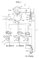
- FIGS.1 to 4 show a wafer edge bevelling machine according to a first embodiment of the present invention.
- FIG.1 shows a pneumatic circuit of a wafer edge bevelling machine according to a first embodiment of the present invention.
- FIG.2 is a view of the wafer edge bevelling machine in the direction of an arrow X in FIG.1.
- FIG.3 is a view of the wafer edge bevelling machine in the direction of an arrow Y in FIG.1.
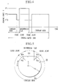
- FIG.4 is a timing chart illustrative of changes in a pushing force F with time.
- an arm is indicated at 1.
- An intermediate of the arm 1 is mounted on a pivot 2 which is fixed to a framework (not shown) of the wafer edge bevelling machine.
- the front end of the arm 1 has a vertical rotatable shaft 4.
- the rotatable shaft 4 has an installed cylindrical buff 3 of urethane foam.
- the outer cylindrical surface of the buff 3 has an annular formed groove 3a.
- the buff 3 is not removed from the rotatable shaft 4 in renewing the formed groove 3a in the buff 3.
- the buff 3 may alternatively be removed from the rotatable shaft 4 in renewing the formed groove 3a in the buff 3.
- the upper end of the rotatable shaft 4 extends upward through the arm 1 and has a pulley 5 fixed thereto.
- a rear end of the arm 1 has an electrical motor 6 mounted thereon.
- the vertical output shaft of the motor 6 has a pulley 7.
- a belt 8 is extended between the pulleys 5 and 7 and passes over the rims of the pulleys 5 and 7.
- An air cylinder assembly 9 is located to a side edge surface of the rear end of the arm 1 for rotating the arm 1 counterclockwise in FIG.1.
- a piston 9b of the air cylinder assembly 9 separates the interior of a cylinder 9a into chambers S1 and S2.
- the front end of a piston rod 9C fixed to the piston 9b is in contact with the side edge surface of the arm 1 as shown in FIGS.1 and 2.
- a suction table 10 is positioned horizontally near the buff 3 and rotatable.
- the top surface of the suction table 10 sucks in place a wafer W the edge of which are to be bevelled.
- a driver (not shown) rotates the suction table 10.
- a photo-sensor 11 sensing the orientation flat W1 of the wafer W (see FIG.5) is positioned near the suction table 10.
- the photo-sensor 11 comprises a pair of a light-emitting unit 11a and a light-receiving unit 11b arranged opposite each other through the wafer W.
- the light-receiving unit 11b receives a beam of light from the light-emitting unit 11a to produce a sensing signal of a voltage proportional to the intensity of the light.
- the circular edge W2 of the wafer W passes through the photo-sensor 11, the circular edge W2 completely intercepts the beam of light from the light-emitting unit 11a.
- the orientation flat W1 passes through the photo-sensor 11, part or all of the light from the light-emitting unit 11a reaches the light-receiving unit 11b, so that the photo-sensor 11 senses the orientation flat W1.
- the photo-sensor 11 produces a sensing signal of the peak voltage.
- a controller 20 comprising an electronic central processing unit (CPU) receives the sensing signal from the photo-sensor 11 and determines the center of the orientation flat W1 from the peak voltage of the sensing signal.
- the determination of the center of the orientation flat W1 determines the positions of the orientation flat W1, the circular edge W2 and the round joints W3 (see FIG.5) since the dimensions of the orientation flat W1 is known to the wafer edge bevelling machine.
- the photo-sensor 11 distinctively senses the orientation flat W1
- the circular edge W2 and the round joints W3 and the wafer edge bevelling machine comprises a control selecting a corresponding one of pressures P1, P2 and P3 (P1>P2>P3) of compressed air supplied to the air cylinder assembly 9 in response to the sensing signals from the photo-sensor 11.
- the control comprises a pneumatic control circuit 30 and the CPU 20.
- the pneumatic control circuit 30 comprises a reference pressure line L0 communicating with a plenum of an air compressor (not shown).
- the reference pressure line L0 has three parallel pairs of a pressure control valve V1 and a solenoid operated valve MV1 connected in series to the pressure control valve V1, a pressure control valve V2 and a solenoid operated valve MV2 connected in series to the pressure control valve V2, and a pressure control valve V3 and a solenoid operated valve MV3 connected in series to the pressure control valve V3.
- the pressure control valve V1 reduces the reference pressure P0 to the pressure P1.
- the pressure control valve V2 reduces the reference pressure P0 to the pressure P2.
- the pressure control valve V3 reduces the reference pressure P0 to the pressure P3.
- the solenoid operated valves MV1, MV2 and MV3 are of a three-position three-port valve switched between positions a, b and c under control of the CPU 20.
- the solenoid operated valves MV1, MV2 and MV3 are in the positions a, compressed air of the pressures P1, P2 and P3 is supplied to the chamber S2 of the air cylinder assembly 9 through reduced-pressure lines L1, L2 and L3.
- the solenoid operated valves MV1, MV2 and MV3 are in the positions b (i.e. neutral positions)
- the solenoid operated valves MV1, MV2 and MV3 interrupt passages (i.e. supplies and discharges) of compressed air of the pressures P1, P2 and P3.
- the solenoid operated valves MV1, MV2 and MV3 When the solenoid operated valves MV1, MV2 and MV3 are in the positions c, the solenoid operated valves MV1, MV2 and MV3 enable compressed air to be discharged from the chamber S2 of the air cylinder assembly 9 to the atmosphere.
- a pressure line L4 is connected to the chamber S1 of the air cylinder assembly 9 and to the reference pressure line L0 or the atmosphere.
- the pressure line L4 has a solenoid operated valve MV4 provided thereintermediate.
- the solenoid operated valve MV4 is a two-position two-port valve controlled by the CPU 20.
- the solenoid operated valve MV4 When the solenoid operated valve MV4 is in the position a, the pressure P0 is supplied from the reference pressure line L0 to the chamber S1 of the air cylinder assembly 9.
- the solenoid operated valve MV4 is in the position b, air is discharged from the chamber S1 to the atmosphere.
- the rotatable shaft 4 and the buff 3 are rotated at a high speed counterclockwise in FIG.1.
- the suction table 10 has sucked the wafer W
- the photosensor 11 sensed the positions of the orientation flat W1, the circular edge W2 and the round joints W3, and the CPU 20 has stored data of these positions.
- the motor 6 is moved to transmit a torque to the rotatable shaft 4 by means of the pulley 7, the belt 8 and the pulley 5.
- the driver (not shown) rotates the suction table 10 and the wafer W counterclockwise in FIG.1.
- the air cylinder assembly 9 drives the piston rod 9c to push the side edge surface of the rear end of the arm 1 by the force F in the direction of the arrow F
- the arm 1 receives a counterclockwise moment about the pivot 2 to push the buff 3 against the edge of the wafer W by the contact pressure ⁇ so that the edge surface of the formed groove 3a in the buff 3 bevels the edge of the wafer W.
- the wafer edge bevelling machine supplies a slurry containing a polishing material to the beveled edge of the wafer W.
- the CPU 20 switches between the pneumatic pressures P1, P2 and P3 supplied to the air cylinder assembly 9 in response to the sensing signals from the photo-sensor 11 to switch between the forces F1, F2 and F3 having a relational expression: F1>F2>F3 and applied to the arm 1 (see FIG.4) so that the three contact pressures ⁇ 1, ⁇ 2 and ⁇ 3 on the orientation flat W1, the circular edges W2 and the round joints W3 are substantially equal.
- wafer edge bevelling machine as shown in FIG.5, bevels the edge of the wafer W clockwise from the point A on the circular edge W2 in FIG.5.
- the CPU 20 causes the solenoid operated valve MV2 to assume the position a and the solenoid operated valves MV1, MV3 and MV4 to assume the positions b.
- the pressure control valve V2 reduces the reference pressure P0 from reference pressure line L0 to the intermediate pressure P2 between P1 and P3.
- the pressure P2 is supplied to the chamber S2 of the air cylinder assembly 9 through the reduced-pressure line L2 to extend the piston rod 9c outside the cylinder 9a. Air is concurrently discharged from the chamber S1 of the air cylinder assembly 9 to the atmosphere through the pressure line L4.
- the piston rod 9c is extended to push the side edge surface of the front end of the arm 1 by the intermediate force F2 between the forces F1 and F3 shown in FIG.4.
- the buff 3 is pressed by the contact pressure ⁇ 2 on the circular edge W2 to bevel the circular edge W2 by polishing.
- the CPU 20 switches the position of the solenoid operated valve MV3 to the position a and the position of the solenoid operated valve MV2 to the position b and continues the other solenoid operated valves MV3 and MV4 to assume the positions b.
- the pressure control valve V3 reduces the reference pressure P0 from the reference pressure line L0 to the lowest pressure P3.
- the pressure P3 is supplied to the chamber S2 of the air cylinder assembly 9 through the reduced-pressure line L3 to extend the piston rod 9c out side the air cylinder 9a. Air is concurrently discharged from the chamber S1 of the air cylinder assembly 9 to the atmosphere through the pressure line L4.
- the piston rod 9c is extended to push the side edge surface of the front end of the arm 1 by the smallest force F3 of the forces F1, F2 and F3 shown in FIG.4.
- the buff 3 is pressed by the contact pressure ⁇ 3 on the round joint W3 to bevel the edge of the round joint W3.
- the CPU 20 switches the position of the solenoid operated valve MV1 to the position a and the position of the solenoid operated valve MV3 to the position b and continues the other solenoid operated valves MV2 and MV4 to assume the positions b.
- the pressure control valve V1 then reduces the reference pressure P0 from the reference pressure line L0 to the highest pressure P1 of the reduced pressures P1, P2 and P3.
- the pressure P1 is supplied to the chamber S2 of the air cylinder assembly 9 through the pressure line L1 to extend the piston rod 9c. Compressed air is concurrently discharged from the chamber S1 of the air cylinder assembly 9 to the atmosphere through the pressure line L4.
- the piston rod 9c is extended to push the side edge surface of the rear end of the arm 1 by the largest force F1 of the forces F1, F2 and F3 shown in FIG.4.
- the buff 3 is then pressed by the contact pressure ⁇ 1 on the orientation flat W1 to bevel the edge of the orientation flat W1.
- the suction table 10 is subsequently rotated to transfer the point of bevelling to the other round joint W3.
- the buff 3 is then pressed by the contact pressure ⁇ 3 on the other round joint W3 to bevel the other round joint W3.
- the suction table 10 is subsequently rotated to again transfer the point of bevelling to the circular edge W2.
- the arm 1 is rotated by the force F2 in the manner described above.
- the buff 3 is pressed by the contact pressure ⁇ 2 on the circular edge W2 to bevel the circular edge W2.
- the wafer edge bevelling machine bevels the edge of the wafer W with a 8-inch diameter by means of the buff 3 with a 150-mm radius and the respective radii R1, R2 and R3 of curvature of the orientation flat W1
- the circular edge W2 and the round joints W3 are ⁇ , 100 mm and 5 mm
- the ratios between the forces F1, F2 and F3 are selected to be 30:13:1 so that the contact pressures ⁇ 1, ⁇ 2 and ⁇ 3 are substantially equal.
- the wafer edge bevelling machine uniformly bevels the orientation flat W1, the circular edge W2 and the round joints W3 by the substantially equal contact pressures and insures an optimal wafer edge bevelling precision over the edge of the wafer W to increase the productivity in the bevelling.
- the first embodiment has the structure of moving the buff 3 to the wafer W for bevelling the edge of the wafer W.
- an alternative embodiment of the present invention may have a structure of moving the wafer W to the buff 3.
- FIGS.6 to 16 show a wafer edge bevelling machine having a cutter for producing a formed-groove in a buff according to a second embodiment of the present invention.
- FIG.6 is a plan view of a wafer edge bevelling machine according to the second embodiment of the present invention.
- FIG.7 is a front elevation of the wafer edge bevelling machine of FIG.6.
- FIG.8 is a right elevation of the wafer edge bevelling machine of FIG.6 in the direction of an arrow A in FIG.6.
- FIG.9 is a left elevation of the wafer edge bevelling machine of FIG.6, showing a state of bevelling the wafer edge.
- an arm is indicated at 41.
- An intermediate of the arm 41 is mounted on a pivot 43 fixed to the front end of a support rod 42 extending from a fixed framework of the wafer edge bevelling machine.
- the front end of the arm 41 has an electrical motor 44 mounted atop it and a rotatable suction table 45 mounted on the underside thereof and rotated by the motor 44.
- a vacuum source (not shown) supplies a negative pressure to the underside of the suction table 45.
- the underside of the suction table 45 sucks the wafer W or a grooving cutter assembly 54 (see, e.g., FIGS.7 and 10).
- a cylindrical buff 46 of urethane foam is installed to an output shaft 48 of a driver 47 near the suction table 45.
- the outer cylindrical surface of the buff 46 has seven annular formed grooves 46a vertically arranged for bevelling the wafer edge.
- Each of the formed grooves 46a has a cross section corresponding to the cross section of the edge to be bevelled of the wafer W.
- the buff 46 is not removed from the output shaft 48 in renewing the formed groove 46a in the buff 46.
- the driver 47 rotates the buff 46 at a predetermined speed and vertically moves the buff 46.
- a piston rod 49a of an air cylinder assembly 49 fixed to the framework of the wafer edge bevelling machine pushes the side edge surface of the rear end of the arm 41.
- the rear end of the arm 41 is connected with one end of a return spring 50 in the form of a tension coil spring, so that the arm 41 is continuously urged in a direction in which the wafer W is moved away from the buff 46 (i.e. clockwise in FIG.6).
- the air cylinder assembly 49 extends the piston rod 49a to rotate the arm 41 about the pivot 43 counterclockwise in FIG.6 and as shown in FIG.9 press the wafer W sucked by the suction table 45 by a predetermined force on the buff 46 during bevelling of the wafer edge.
- the air cylinder assembly 49 has substantially the same structure as the air cylinder assembly 9 of the first embodiment of the present invention. That is, the air cylinder assembly 49 may have three output pressures corresponding to the three output pressures P1, P2 and P3 in bevelling the wafer edge.
- a stopper 51 in the form of an air cylinder assembly having a piston rod 51a is fixed to the framework of the wafer edge bevelling machine in order to position the tip of a cemented carbide tipped tool 54b of a grooving cutter assembly 54 relative to the outer cylindrical surface of the buff 46.
- the piston rod 51a of the stopper 51 is aligned with the piston rod 49a of the air cylinder assembly 49. Therefore, when the stopper 51 operates as shown in FIG.6, the arm 41 is rigidly precisely positioned at right angle to the axis of the support rod 42.
- the driver 47 rotates the buff 46 at a high speed.
- the suction table 45 is rotated at a low speed by the motor 44 and concurrently receives the negative pressure, so that the suction table 45 rotates the wafer W at the low speed while sucking the wafer W.
- the air cylinder assembly 49 extends the piston rod 49a by predetermined distances to push the side edge surface of the rear end of the arm 41 by the forces corresponding to the forces F1, F2 and F3 to rotate the arm 41 about the pivot 43 against the force of the return spring 50 counterclockwise in FIG.6.
- the edge of the wafer W sucked by the suction table 45 is pressed on the edge surface of one of the formed groove 46a in the buff 46 while the motor 44 rotates the suction table 45 at the low speed.
- a nozzle 52 supplies a slurry 53 containing a polishing material to the point of bevelling of the edge of the wafer W, a relative sliding between the edge of the wafer W and the edge surface of the one of the formed groove 46a and the polishing operation of the slurry 53 together bevel the edge of the wafer W.
- Bevelling the edges of many wafers W produces a permanent set in fatigue in the edge surfaces of the formed grooves 46a, so that the shape of the cross section of each formed groove 46a becomes to disagree from a target shape of the cross section of the edge of the wafer W.
- the wafer edge bevelling machine renews the formed grooves 46a in the buff 46 by means of the grooving cutter assembly 54.
- the wafer edge bevelling machine interrupts bevelling the edge of the wafer W and the supply of the slurry 53 by the nozzle 52.
- the wafer suction table 45 sucks the grooving cutter assembly 54 while the output shaft 48 of the driver 47 has the buff 46.
- a locking jig 55 fastened by means of bolts 56 to the front end of the arm 41 locks the rotation of the suction table 45 during renewal of the formed grooves 46a.
- a rectangular hole 55a in the front end of the locking jig 55 fits a rectangular end of the output shaft 44a of the motor 44 to lock the rotation of the output shaft 44a of the motor 44 and therefore the suction table 45.
- FIG.13 is a bottom view of the grooving cutter assembly 54.
- FIG.14 is a sectional view taken along Line B-B in FIG.13.
- FIG.15 is a view in the direction of the arrow C in FIG.14.
- the grooving cutter assembly 54 comprises a disc 54a sucked by the suction table 45, a holder 54a-1 projecting from the underside of the disc 54a, a cemented carbide tipped tool 54b fitted into a groove 54a-2 defined in the holder 54a-1, and a cover 54a-3 covering the underside of the cemented carbide tipped tool 54b and fixed by the bolts 57 to the underside of the holder.
- the tip of the cemented carbide tipped tool 54b extends radially from the edge of the disc 54a.
- the cemented carbide tipped tool 54b bites the buff 46 by a predetermined depth (i.e. a depth by which the cemented carbide tipped tool 54b can completely shave the old formed grooves 46a).
- the driver 47 moves the buff 46 upwards so that the cemented carbide tipped tool 54b shaves an outer surface layer of the buff 46 by the predetermined depth to gradually smooth the outer cylindrical surface 46b from the top to the bottom of the buff 46.
- the piston rod 51a of the stopper 51 precisely positions the tip of the cemented carbide tipped tool 54b relative to the buff 46 (i.e. provides a precise biting depth in the buff 46).
- FIG.16 is a graph of changes with time in the height H of the buff 46 and in the pressure of compressed air supplied to the air cylinder assembly 49.
- the air cylinder assembly 49 receives a fixed pressure P A , and the driver 47 moves the buff 46 at a predetermined speed by a height difference ⁇ H between the lower limit and the upper limit of the movement of the buff 46 until the completion of the smoothing.
- the pressure P A is so high that the air cylinder assembly 49 precisely positions and rigidly fixes together with the stopper 51 the grooving cutter assembly 54 relative to the buff 46.
- the grooving cutter assembly 54 precisely smooth the outer cylindrical surface of the buff 46.
- the cemented carbide tipped tool 54b completes shaving the old formed grooves 46a from the buff 46 to smooth the overall outer cylindrical surface of the buff 46, i.e., renew the outer cylindrical surface of the buff 46.
- the wafer edge bevelling machine stops supplying the pressure P A to the air cylinder assembly 49 as shown in FIG.16.
- the return spring 50 then rotates the arm 41 about the pivot 43 clockwise in FIG.6.
- the driver 47 then moves the buff 46 up to the lower limit of the movement of the buff 46 (see FIG.16).
- the driver 47 then moves up the buff 46 by a predetermined height difference ⁇ h (see FIG.16) and the stopper 51 concurrently contracts a rod 51a by a predetermined distance.
- the air cylinder assembly 49 then receives the pressure P A again as shown in FIG.16 to rotate the arm 41 counterclockwise in FIG.6 by a predetermined angular distance.
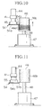
- the cemented carbide tipped tool 54b then bites the buff 46 by a predetermined depth and produces a new first formed groove 46A having a predetermined cross section and a predetermined size in the renewed outer cylindrical surface 46b of the buff 46 at the bottom end of the buff 46 as the driver 47 rotates the buff 46, as shown in FIG.12.
- the wafer edge bevelling machine stops supplying the pressure P A to the air cylinder assembly 49.
- the return spring 50 then rotates the arm 41 about the pivot 43 clockwise in FIG.6 to remove the cemented carbide tipped tool 54b from the buff 46.
- the driver 47 then moves the buff 46 by the predetermined height difference ⁇ h.
- the air cylinder assembly 49 then receives the pressure P A .
- the cemented carbide tipped tool 54b produces a second new formed groove 46A above the first formed groove 46A.
- repeating the grooving provides a plurality of new annular formed grooves 46A (e.g. seven) arranged axially of the buff 46. These new formed grooves 46A serve to bevel the edge of the wafer W.
- the buff 46 need not be removed from the output shaft 48 of the driver 47 when the wafer edge bevelling machine originally produces or renews the formed grooves in the buff 46 so that the grooving does not adversely affect the installation precision of the buff 46 to the output shaft 48 of the driver 47.
- the stopper 51 precisely stops the rotation of the arm 41 to precisely position the cemented carbide tipped tool 54b to precisely determine the biting depth of the cemented carbide tipped tool 54b in the buff 46. This insures the precise shaping of the formed grooves 46A.
- the suction table 45 sucks the grooving cutter assembly 54 in place only when the wafer edge bevelling machine shapes the formed grooves in the buff 46, so that the grooving cutter assembly 54 is not exposed to the polishing slurry 53. Consequently, the wafer edge bevelling machine eliminates the need for measures for the slurry 53 and the need for the employment of a grooving cutter of an expensive material.
- the suction table 45 can quickly precisely suck and install the grooving cutter assembly 54 in substantially the same manner as the suction table 45 sucks the wafer W, so that the wafer edge bevelling machine can easily efficiently produce the formed grooves 46A in the buff 46.
Landscapes
- Engineering & Computer Science (AREA)
- Mechanical Engineering (AREA)
- Chemical & Material Sciences (AREA)
- Ceramic Engineering (AREA)
- Inorganic Chemistry (AREA)
- Grinding And Polishing Of Tertiary Curved Surfaces And Surfaces With Complex Shapes (AREA)
- Mechanical Treatment Of Semiconductor (AREA)
Applications Claiming Priority (4)
| Application Number | Priority Date | Filing Date | Title |
|---|---|---|---|
| JP4317041A JP3006322B2 (ja) | 1992-11-26 | 1992-11-26 | ウエーハ面取部研磨装置 |
| JP317041/92 | 1992-11-26 | ||
| JP318445/92 | 1992-11-27 | ||
| JP4318445A JP2762200B2 (ja) | 1992-11-27 | 1992-11-27 | ウエーハ面取部研磨用バフの総形溝加工装置 |
Publications (2)
| Publication Number | Publication Date |
|---|---|
| EP0601748A1 true EP0601748A1 (de) | 1994-06-15 |
| EP0601748B1 EP0601748B1 (de) | 1996-09-04 |
Family
ID=26568901
Family Applications (1)
| Application Number | Title | Priority Date | Filing Date |
|---|---|---|---|
| EP93309445A Expired - Lifetime EP0601748B1 (de) | 1992-11-26 | 1993-11-26 | Maschine zum Kantenscheifen von Halbleiterplatten |
Country Status (3)
| Country | Link |
|---|---|
| US (1) | US5538463A (de) |
| EP (1) | EP0601748B1 (de) |
| DE (1) | DE69304498T2 (de) |
Cited By (11)
| Publication number | Priority date | Publication date | Assignee | Title |
|---|---|---|---|---|
| GB2289982A (en) * | 1994-06-02 | 1995-12-06 | Tokyo Seimitsu Co Ltd | Apparatus and method for manufacturing chamfered semiconductor wafers |
| EP0687524A1 (de) * | 1994-06-17 | 1995-12-20 | Shin-Etsu Handotai Company Limited | Verfahren und Vorrichtung zum Hochglanzpolieren eines Teiles von einem Wafer |
| EP0832717A3 (de) * | 1996-09-27 | 1998-11-11 | Shin-Etsu Handotai Co., Ltd | Halbleiterscheibenfertigung |
| EP0734811A3 (de) * | 1995-03-31 | 1999-05-26 | Shin-Etsu Handotai Co., Ltd. | Verfahren und Vorrichtung zum Hochglanzpolieren von Fasen eines Wafers mit einer Orientierungs-Aufflachung |
| WO1999067054A1 (en) * | 1998-06-25 | 1999-12-29 | Unova U.K. Limited | Wafer edge polishing method and apparatus |
| EP1200228A1 (de) * | 1999-07-03 | 2002-05-02 | Unova U.K. Limited | Kantenschleifverfahren |
| EP0945216A3 (de) * | 1998-03-25 | 2002-07-17 | Unova U.K. Limited | Kerben-Schleifwerkzeug |
| WO2005012195A3 (en) * | 2003-07-29 | 2005-04-14 | Corning Inc | Pressure feed grinding of amlcd substrate edges |
| CN102806514A (zh) * | 2012-07-31 | 2012-12-05 | 濮阳贝英数控机械设备有限公司 | 气动超精机油石高低压自动控制回路及工作方法 |
| US8585467B2 (en) | 2008-10-31 | 2013-11-19 | Corning Incorporated | Linear pressure feed grinding with voice coil |
| US8721392B2 (en) | 2011-06-28 | 2014-05-13 | Corning Incorporated | Glass edge finishing method |
Families Citing this family (12)
| Publication number | Priority date | Publication date | Assignee | Title |
|---|---|---|---|---|
| JPH08243891A (ja) * | 1995-03-07 | 1996-09-24 | Kao Corp | 基板のチャンファ加工装置 |
| JPH10249689A (ja) * | 1997-03-10 | 1998-09-22 | Tokyo Seimitsu Co Ltd | ウェーハ面取方法及び装置 |
| JP3942802B2 (ja) * | 2000-04-28 | 2007-07-11 | 株式会社ニデック | 眼鏡レンズ加工装置 |
| KR100597637B1 (ko) * | 2004-06-14 | 2006-07-05 | 삼성전자주식회사 | 반도체 제조설비의 리프트 오동작 제어장치 및 그 방법 |
| JP4486003B2 (ja) * | 2005-07-07 | 2010-06-23 | 大日本スクリーン製造株式会社 | 基板洗浄ブラシ、ならびにこれを用いた基板処理装置および基板処理方法 |
| US20070238393A1 (en) * | 2006-03-30 | 2007-10-11 | Shin Ho S | Methods and apparatus for polishing an edge of a substrate |
| US20070298240A1 (en) * | 2006-06-22 | 2007-12-27 | Gobena Feben T | Compressible abrasive article |
| US20090114268A1 (en) * | 2006-11-15 | 2009-05-07 | Solyndra, Inc. | Reinforced solar cell frames |
| JP2008284684A (ja) * | 2007-05-21 | 2008-11-27 | Applied Materials Inc | 研磨アームを使用して基板の縁部を研磨する方法及び装置 |
| US11105714B2 (en) * | 2016-10-19 | 2021-08-31 | Madad Pty. Ltd. | Method and apparatus for testing rolling resistance |
| WO2021212029A1 (en) * | 2020-04-17 | 2021-10-21 | Amsted Rail Company, Inc. | Systems and methods for polishing a cylindrical lip-seal surface |
| TWI777835B (zh) * | 2021-10-29 | 2022-09-11 | 魏英州 | 具自動補償施壓復位之拋光設備 |
Citations (3)
| Publication number | Priority date | Publication date | Assignee | Title |
|---|---|---|---|---|
| US4031667A (en) * | 1976-03-29 | 1977-06-28 | Macronetics, Inc. | Apparatus for contouring edge of semiconductor wafers |
| EP0205054A2 (de) * | 1985-06-10 | 1986-12-17 | Peter Wolters Ag | Steuervorrichtung für den Bearbeitungsdruck an Läpp-, Hon- und Poliermaschinen |
| EP0457364A2 (de) * | 1985-11-04 | 1991-11-21 | Silicon Technology Corporation | Automatische Kantenschleifmaschine |
Family Cites Families (10)
| Publication number | Priority date | Publication date | Assignee | Title |
|---|---|---|---|---|
| US3325946A (en) * | 1964-10-22 | 1967-06-20 | Raybestos Manhattan Inc | Cutoff machine |
| US3798843A (en) * | 1972-04-27 | 1974-03-26 | Clair Mfg Co | Automatic buff pressure setting |
| JPS5314554A (en) * | 1976-07-26 | 1978-02-09 | Mitsubishi Metal Corp | Method of chamfering single crystal wafer |
| US4286415A (en) * | 1979-03-12 | 1981-09-01 | Ait Industries, Inc. | Method of edging lenses |
| GB2173300B (en) * | 1985-04-06 | 1989-06-28 | Schaudt Maschinenbau Gmbh | Apparatus for optically monitoring the surface finish of ground workpieces |
| JPS6237925A (ja) * | 1985-08-12 | 1987-02-18 | Nissin Electric Co Ltd | 基板ホルダ |
| US4974368A (en) * | 1987-03-19 | 1990-12-04 | Canon Kabushiki Kaisha | Polishing apparatus |
| US5177901A (en) * | 1988-11-15 | 1993-01-12 | Smith Roderick L | Predictive high wheel speed grinding system |
| US5094037A (en) * | 1989-10-03 | 1992-03-10 | Speedfam Company, Ltd. | Edge polisher |
| JP2559076B2 (ja) * | 1990-06-28 | 1996-11-27 | キヤノン株式会社 | プリアライメント装置 |
-
1993
- 1993-11-24 US US08/156,829 patent/US5538463A/en not_active Expired - Fee Related
- 1993-11-26 EP EP93309445A patent/EP0601748B1/de not_active Expired - Lifetime
- 1993-11-26 DE DE69304498T patent/DE69304498T2/de not_active Expired - Fee Related
Patent Citations (3)
| Publication number | Priority date | Publication date | Assignee | Title |
|---|---|---|---|---|
| US4031667A (en) * | 1976-03-29 | 1977-06-28 | Macronetics, Inc. | Apparatus for contouring edge of semiconductor wafers |
| EP0205054A2 (de) * | 1985-06-10 | 1986-12-17 | Peter Wolters Ag | Steuervorrichtung für den Bearbeitungsdruck an Läpp-, Hon- und Poliermaschinen |
| EP0457364A2 (de) * | 1985-11-04 | 1991-11-21 | Silicon Technology Corporation | Automatische Kantenschleifmaschine |
Cited By (19)
| Publication number | Priority date | Publication date | Assignee | Title |
|---|---|---|---|---|
| US5582536A (en) * | 1994-06-02 | 1996-12-10 | Tokyo Seimitsu Co., Ltd. | Apparatus and method for manufacturing wafer |
| GB2289982B (en) * | 1994-06-02 | 1998-06-24 | Tokyo Seimitsu Co Ltd | Apparatus and method for manufacturing wafer |
| GB2289982A (en) * | 1994-06-02 | 1995-12-06 | Tokyo Seimitsu Co Ltd | Apparatus and method for manufacturing chamfered semiconductor wafers |
| EP0687524A1 (de) * | 1994-06-17 | 1995-12-20 | Shin-Etsu Handotai Company Limited | Verfahren und Vorrichtung zum Hochglanzpolieren eines Teiles von einem Wafer |
| US5727990A (en) * | 1994-06-17 | 1998-03-17 | Shin-Etsu Handotai Co., Ltd. | Method for mirror-polishing chamfered portion of wafer and mirror-polishing apparatus |
| EP0734811A3 (de) * | 1995-03-31 | 1999-05-26 | Shin-Etsu Handotai Co., Ltd. | Verfahren und Vorrichtung zum Hochglanzpolieren von Fasen eines Wafers mit einer Orientierungs-Aufflachung |
| EP0832717A3 (de) * | 1996-09-27 | 1998-11-11 | Shin-Etsu Handotai Co., Ltd | Halbleiterscheibenfertigung |
| EP0945216A3 (de) * | 1998-03-25 | 2002-07-17 | Unova U.K. Limited | Kerben-Schleifwerkzeug |
| US6428397B1 (en) | 1998-06-25 | 2002-08-06 | Unova U.K. Limited | Wafer edge polishing method and apparatus |
| WO1999067054A1 (en) * | 1998-06-25 | 1999-12-29 | Unova U.K. Limited | Wafer edge polishing method and apparatus |
| EP1200228A1 (de) * | 1999-07-03 | 2002-05-02 | Unova U.K. Limited | Kantenschleifverfahren |
| WO2005012195A3 (en) * | 2003-07-29 | 2005-04-14 | Corning Inc | Pressure feed grinding of amlcd substrate edges |
| US7018272B2 (en) | 2003-07-29 | 2006-03-28 | Corning Incorporated | Pressure feed grinding of AMLCD substrate edges |
| US7207866B2 (en) | 2003-07-29 | 2007-04-24 | Corning Incorporated | Pressure feed grinding of AMLCD substrate edges |
| CN100569443C (zh) * | 2003-07-29 | 2009-12-16 | 康宁股份有限公司 | Amlcd基板边缘的压力进给研磨 |
| US8585467B2 (en) | 2008-10-31 | 2013-11-19 | Corning Incorporated | Linear pressure feed grinding with voice coil |
| US8814633B2 (en) | 2008-10-31 | 2014-08-26 | Corning Incorporated | Linear pressure feed grinding with voice coil |
| US8721392B2 (en) | 2011-06-28 | 2014-05-13 | Corning Incorporated | Glass edge finishing method |
| CN102806514A (zh) * | 2012-07-31 | 2012-12-05 | 濮阳贝英数控机械设备有限公司 | 气动超精机油石高低压自动控制回路及工作方法 |
Also Published As
| Publication number | Publication date |
|---|---|
| DE69304498D1 (de) | 1996-10-10 |
| DE69304498T2 (de) | 1997-04-03 |
| EP0601748B1 (de) | 1996-09-04 |
| US5538463A (en) | 1996-07-23 |
Similar Documents
| Publication | Publication Date | Title |
|---|---|---|
| US5538463A (en) | Apparatus for bevelling wafer-edge | |
| US7189149B2 (en) | Method of truing chamfering grindstone and chamfering device | |
| US5679065A (en) | Wafer carrier having carrier ring adapted for uniform chemical-mechanical planarization of semiconductor wafers | |
| EP0544256B1 (de) | Verfahren zum Abkanten einer Halbleiterscheibe | |
| US7217175B2 (en) | Polishing apparatus and polishing method | |
| US7858530B2 (en) | Processing method for wafer and processing apparatus therefor | |
| KR102008100B1 (ko) | 연마 장치 및 연마 방법 | |
| JP5988765B2 (ja) | ウェーハの面取り加工方法、ウェーハの面取り加工装置および砥石角度調整用治具 | |
| GB2331948A (en) | Polishing machine for flattening substrate surface. | |
| US20090156104A1 (en) | Grinding wheel truing tool and manufacturing method thereof, and truing apparatus, method for manufacturing grinding wheel and wafer edge grinding apparatus using the same | |
| JP2007059828A (ja) | 研磨方法及び研磨装置 | |
| JP2009038267A (ja) | 基板の裏面研削装置および裏面研削方法 | |
| US3816997A (en) | Apparatus for simultaneously performing rough and fine grinding operations | |
| JP2008124292A (ja) | 加工装置のウエーハ位置調整治具 | |
| EP1034883A1 (de) | Verfahren und Vorrichtung zum Abfasen von Halbleiterscheiben | |
| TW202304640A (zh) | 工件加工裝置、磨石及工件加工方法 | |
| JPH0740214A (ja) | ウェーハ外周部の研磨装置 | |
| US6796887B2 (en) | Wear ring assembly | |
| EP0832717A2 (de) | Halbleiterscheibenfertigung | |
| US12479053B2 (en) | Holding table assembly and processing method | |
| JPH11309666A (ja) | ウェーハの平面加工装置 | |
| US6995850B2 (en) | Monitoring apparatus for polishing pad and method thereof | |
| US20240424637A1 (en) | Back grinding apparatus and wear amount measuring method using the same | |
| EP1577068B1 (de) | Handsäge mit Führungsfunktion | |
| GB2299206A (en) | Dicing machine |
Legal Events
| Date | Code | Title | Description |
|---|---|---|---|
| PUAI | Public reference made under article 153(3) epc to a published international application that has entered the european phase |
Free format text: ORIGINAL CODE: 0009012 |
|
| AK | Designated contracting states |
Kind code of ref document: A1 Designated state(s): DE FR GB |
|
| 17P | Request for examination filed |
Effective date: 19940929 |
|
| 17Q | First examination report despatched |
Effective date: 19950324 |
|
| GRAH | Despatch of communication of intention to grant a patent |
Free format text: ORIGINAL CODE: EPIDOS IGRA |
|
| GRAH | Despatch of communication of intention to grant a patent |
Free format text: ORIGINAL CODE: EPIDOS IGRA |
|
| GRAA | (expected) grant |
Free format text: ORIGINAL CODE: 0009210 |
|
| AK | Designated contracting states |
Kind code of ref document: B1 Designated state(s): DE FR GB |
|
| REF | Corresponds to: |
Ref document number: 69304498 Country of ref document: DE Date of ref document: 19961010 |
|
| ET | Fr: translation filed | ||
| PLBE | No opposition filed within time limit |
Free format text: ORIGINAL CODE: 0009261 |
|
| 26N | No opposition filed | ||
| PGFP | Annual fee paid to national office [announced via postgrant information from national office to epo] |
Ref country code: FR Payment date: 19981110 Year of fee payment: 6 |
|
| PGFP | Annual fee paid to national office [announced via postgrant information from national office to epo] |
Ref country code: GB Payment date: 19981127 Year of fee payment: 6 |
|
| PGFP | Annual fee paid to national office [announced via postgrant information from national office to epo] |
Ref country code: DE Payment date: 19981207 Year of fee payment: 6 |
|
| PG25 | Lapsed in a contracting state [announced via postgrant information from national office to epo] |
Ref country code: GB Free format text: LAPSE BECAUSE OF NON-PAYMENT OF DUE FEES Effective date: 19991126 |
|
| GBPC | Gb: european patent ceased through non-payment of renewal fee |
Effective date: 19991126 |
|
| PG25 | Lapsed in a contracting state [announced via postgrant information from national office to epo] |
Ref country code: FR Free format text: LAPSE BECAUSE OF NON-PAYMENT OF DUE FEES Effective date: 20000731 |
|
| REG | Reference to a national code |
Ref country code: FR Ref legal event code: ST |
|
| PG25 | Lapsed in a contracting state [announced via postgrant information from national office to epo] |
Ref country code: DE Free format text: LAPSE BECAUSE OF NON-PAYMENT OF DUE FEES Effective date: 20001003 |