EP0601773A1 - Façonnage de joints soudés par diffusion sur des structures métalliques réalisées par formage superplastique - Google Patents
Façonnage de joints soudés par diffusion sur des structures métalliques réalisées par formage superplastique Download PDFInfo
- Publication number
- EP0601773A1 EP0601773A1 EP93309566A EP93309566A EP0601773A1 EP 0601773 A1 EP0601773 A1 EP 0601773A1 EP 93309566 A EP93309566 A EP 93309566A EP 93309566 A EP93309566 A EP 93309566A EP 0601773 A1 EP0601773 A1 EP 0601773A1
- Authority
- EP
- European Patent Office
- Prior art keywords
- sheets
- clenching
- faces
- die
- metal
- Prior art date
- Legal status (The legal status is an assumption and is not a legal conclusion. Google has not performed a legal analysis and makes no representation as to the accuracy of the status listed.)
- Granted
Links
- 229910052751 metal Inorganic materials 0.000 title claims abstract description 57
- 239000002184 metal Substances 0.000 title claims abstract description 57
- 238000009792 diffusion process Methods 0.000 title claims abstract description 17
- 238000000034 method Methods 0.000 claims abstract description 24
- 239000000463 material Substances 0.000 claims abstract description 8
- 238000009721 upset forging Methods 0.000 claims abstract description 6
- 238000010438 heat treatment Methods 0.000 claims abstract description 3
- 230000002093 peripheral effect Effects 0.000 claims description 5
- 238000005242 forging Methods 0.000 claims description 3
- 238000009966 trimming Methods 0.000 abstract description 4
- 239000011261 inert gas Substances 0.000 description 4
- 238000000926 separation method Methods 0.000 description 4
- 230000000694 effects Effects 0.000 description 3
- RTAQQCXQSZGOHL-UHFFFAOYSA-N Titanium Chemical group [Ti] RTAQQCXQSZGOHL-UHFFFAOYSA-N 0.000 description 2
- 239000007789 gas Substances 0.000 description 2
- 229910001092 metal group alloy Inorganic materials 0.000 description 2
- 230000003014 reinforcing effect Effects 0.000 description 2
- 239000010936 titanium Substances 0.000 description 2
- 229910052719 titanium Inorganic materials 0.000 description 2
- 230000015572 biosynthetic process Effects 0.000 description 1
- 238000007664 blowing Methods 0.000 description 1
- 238000003486 chemical etching Methods 0.000 description 1
- 230000001010 compromised effect Effects 0.000 description 1
- 239000012530 fluid Substances 0.000 description 1
- 238000007373 indentation Methods 0.000 description 1
- 238000002347 injection Methods 0.000 description 1
- 239000007924 injection Substances 0.000 description 1
- 238000004519 manufacturing process Methods 0.000 description 1
- 239000000203 mixture Substances 0.000 description 1
Images
Classifications
-
- B—PERFORMING OPERATIONS; TRANSPORTING
- B21—MECHANICAL METAL-WORKING WITHOUT ESSENTIALLY REMOVING MATERIAL; PUNCHING METAL
- B21D—WORKING OR PROCESSING OF SHEET METAL OR METAL TUBES, RODS OR PROFILES WITHOUT ESSENTIALLY REMOVING MATERIAL; PUNCHING METAL
- B21D26/00—Shaping without cutting otherwise than using rigid devices or tools or yieldable or resilient pads, i.e. applying fluid pressure or magnetic forces
- B21D26/02—Shaping without cutting otherwise than using rigid devices or tools or yieldable or resilient pads, i.e. applying fluid pressure or magnetic forces by applying fluid pressure
- B21D26/053—Shaping without cutting otherwise than using rigid devices or tools or yieldable or resilient pads, i.e. applying fluid pressure or magnetic forces by applying fluid pressure characterised by the material of the blanks
- B21D26/055—Blanks having super-plastic properties
-
- B—PERFORMING OPERATIONS; TRANSPORTING
- B23—MACHINE TOOLS; METAL-WORKING NOT OTHERWISE PROVIDED FOR
- B23K—SOLDERING OR UNSOLDERING; WELDING; CLADDING OR PLATING BY SOLDERING OR WELDING; CUTTING BY APPLYING HEAT LOCALLY, e.g. FLAME CUTTING; WORKING BY LASER BEAM
- B23K20/00—Non-electric welding by applying impact or other pressure, with or without the application of heat, e.g. cladding or plating
- B23K20/02—Non-electric welding by applying impact or other pressure, with or without the application of heat, e.g. cladding or plating by means of a press ; Diffusion bonding
- B23K20/023—Thermo-compression bonding
Definitions
- This invention relates to forming of diffusion bonded joints in superplastically formed hollow metal structures and in particular to the joint integrity of peripheral diffusion bonded joints between adjacent sheets of material following removal of an external flange from the region of the joint.
- the term 'superplastic forming' used in this specification refers to characteristics exhibited by a known class of metallic alloys which have a composition and microstructure such that when heated to within an appropriate temperature range and deformed within an appropriate range of strain rate, the metal takes on the flow characteristics of a plastic material, that is to say it has the flow characteristics of a viscous fluid. With such metallic alloys, large deformations are possible without fracture.
- the term 'diffusion bonding' used in this specification refers to a process which forms a metallurgical bond by the application of heat and pressure to metal pieces held in close contact for a given length of time.
- a hollow structure is formed from two, or more, usually four, initially flat or sculpted sheets clamped together between opposite halves of a die. Injection of a pressurised inert gas between the sheets when in the die blows the sheets out to take up the form of the die (and in the inner sheets to form a reinforcing core) and thus form a hollow structure. It is necessary during this blowing operation, when superplastic forming of the metal takes place, for clenching faces disposed along the split line of the die to clench the sheets of metal together to form a gas-tight seal therebetween. This clenching force also has the effect of diffusion bonding the sheets to one another as a flange to form a unitary structure.
- a method of forming a diffusion bonded joint during superplastic forming of a hollow metal structure from sheet material using a two piece die having opposed clenching faces disposed along a split line thereof, the structure being formed with a joint at the split line including the steps of:
- the method of the invention thus enables superplastic metal flow to occur within the sheets between the clenching faces during superplastic forming of the structure and therefore allows the maximum possible amount of metal flow into the die cavity.
- At least four sheets may be placed between the clenching faces of the die in which two outer sheets may be superplastically formed into direct contact with internal surfaces of the die and at least two inner sheets may be superplastically formed into a core of the metal structure.
- the increase in pressure on the sheets may be applied when sheets which come into direct contact with the internal die surfaces have contacted same in the region of the split line. This contact will prevent or severely reduce any further superplastic extension of the sheet material in that region.
- the increase in pressure on the sheets may be applied when the two outer sheets have substantially completed superplastic deformation to the shape of the die.
- the pressure sufficient to locate the sheets during superplastic forming thereof may be substantially 1,000 lb per square inch. (70.3 kgf/cm2) and the pressure increase on the sheets via the clenching faces may be to substantially 1,500 lb per square inch (105.5 kgf/cm2) to upset forge the metal.
- a temperature range between 810 degrees C and 930 degrees C is suitable for superplastic forming.
- the step of increasing pressure on the sheets via the clenching faces to upset forge the metal may comprise bringing the clenching faces closer together until limit stops are reached, to ensure consistency of geometry of the formed structure.
- the upset forging step may be carried out by bringing together said clenching faces, at least one of which has at least a portion thereof tapered or angled away from the other in the direction of the die interior.
- At least one of the sheets placed may comprise a relatively thicker region in the vicinity of the clenching faces and at least one relatively thinner region elsewhere.
- This relatively thicker region may extend a substantial distance from the vicinity of the clenching faces and may cover a whole wall section adjacent the clenching faces. This relatively thicker section ensures sufficient metal to be upset forged is present between the clenching faces for a given design of structure.
- a two-piece die for super- plastically forming and diffusion bonding a hollow metal structure from at least two sheets of metal, the die having opposed clenching faces disposed along a split line thereof for forming a peripheral flange joint of the structure by diffusion bonding, wherein the die includes means for applying a first pressure to the sheets via the clenching faces sufficient to locate the sheets whilst allowing superplastic metal flow in the sheets between the faces, means to apply a higher forging pressure to the sheets at a pre-determined time in the forming cycle and means to direct metal upset forged from between the faces towards the interior of the die.
- the means to direct the upset forged metal may comprise a taper applied to at least part of at least one clenching face. Both clenching faces are preferably tapered and may be tapered at an included angle of between 5 degrees and 30 degrees, preferably substantially 10 degrees.
- the at least one tapered clenching face preferably includes a non tapered portion adapted to contact the sheet before the tapered part thereof.
- This non tapered portion, or 'flat' is dimensioned so as to make a shallow indentation in the sheet material to 'nip' same and prevent slippage thereof.
- the adjacent tapered part however, allows clenching movement of the clenching face to cease when the area of clenching face applied to the sheet reaches a predetermined level.
- a die and sheet metal assembly for superplastically forming and diffusion bonding a hollow structure comprising a two-piece die according to the second aspect of the invention and at least two metal sheets placed between the clenching faces of the die, at least one sheet having a relatively thicker region in the vicinity of the clenching faces and at least one relatively thinner region elsewhere.
- a hollow metal structure when manufactured according to the method of the first aspect of the invention.
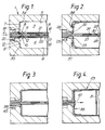
- a two-piece die 1 having a split line at 2.
- the die 1 is hollow having an internal cavity split into an upper cavity 3 and a lower cavity 4. These cavities are bounded by upper and lower inner walls 5, 6 respectively and end walls 7, 8 which lie adjacent upper and lower tapered clenching faces 9, 10 which surround the cavities 3 and 4. Die corners 34, 35 join inner walls 5, 7 and 6, 8 respectively.
- Each clenching face 9, 10 is tapered away from the other, in the direction of the interior of the die 1 (and in the direction of the interior of a structure to be formed), across tapered portions 11, 12.
- Each clenching face 9 and 10 also consists of a small flat portion 13, 14.
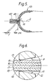
- Clenched between the clenching faces 9, 10 are four pre-sculpted titanium sheets 15, 16, 17, 18. Each sheet is sculpted by known chemical etching methods not further described here. The reason for the pre-sculpting of each sheet is to assist superplastic forming of each sheet to its desired structural shape within the die. Sheets 15 and 18 have relatively thicker regions 19, 20 respectively in the vicinity of the clenching faces 9, 10 and have relatively thinner regions 21, 22 respectively spaced from the clenching faces 9, 10 and positioned to lie along upper and lower inner walls 5, 6 respectively when formed. Inner sheets 16, 17 are known as "core sheets" because they are formed later in the superplastic forming cycle into a reinforcing core for a structure 43 (see Figure 4 and Figure 5).
- core sheets 16, 17 each have relatively thicker regions 24, 25 in the vicinity of the clenching faces 9, 10, relatively thinner regions 26, 27 spaced from the clenching faces 9, 10 and second relatively thicker regions 28, 29 welded together at 30.
- the weld 30 keeps the core sheets 16, 17 in contact throughout and enables the superplastic formation of an inner structural wall 31 automatically.
- the tapered portions 11, 12 of the upper and lower clenching faces 9, 10 and the upper and lower end inner walls 7, 8 of the die define corners 32, 33 at intersections thereof.
- Upper and lower outer sheets 15, 18 are drawn around these corners 32, 33 during the superplastic forming process.
- Inert gas is introduced between sheets 15, 16 and 17, 18 at the same time and pressure and later between core sheets 16 and 17 by nozzles inserted between the sheets (not shown).
- the die 1 is opened and the four sheets 15, 16, 17, 18 are laid on the lower clenching face 10.
- the upper clenching face 9 is then brought down to contact the uppermost sheet 15, the nozzles being inserted between the sheets before placing in the die.
- the assembly of die 1 and sheets 15, 16, 17, 18 is then placed in an oven to raise it to a temperature at which superplastic forming can take place, approximately 1700 degrees Fahrenheit (927 degrees Celcius).
- a clench load is applied to the sheets by the clenching faces 9, 10 of approximately 1,000 1bs per square inch with the tool at 927 degrees C.
- This pressure is enough to "nip" the upper and lower sheets 15, 16 to locate same during superplastic forming but is insufficient substantially to deform the sheets which would restrict superplastic flow of metal along each sheet between the clenching faces during the superplastic forming operation.
- Inert gas is now introduced between sheets 15, 16 and 17, 18 at the same time and pressure to blow the sheets 15 and 18 progressively to the shape of the die.
- inert gas is introduced between sheets 16 and 17 to blow them apart to form a core 38, as shown in Figure 4.
- the clenching faces 9 and 10 are moved closer together until limit stop 39 engages surface 40.
- Metal from all four sheets 15, 16, 17, 18 is upset forged in the direction of the arrow (see Figure 4) owing to the urging effect of each tapered portion 11, 12. This has the effect of moving a line of separation 41 of sheets 16 and 17 inwardly towards to the centre of the die 1 in the direction of the arrow.
Landscapes
- Engineering & Computer Science (AREA)
- Mechanical Engineering (AREA)
- Physics & Mathematics (AREA)
- Fluid Mechanics (AREA)
- Shaping Metal By Deep-Drawing, Or The Like (AREA)
- Pressure Welding/Diffusion-Bonding (AREA)
Applications Claiming Priority (2)
| Application Number | Priority Date | Filing Date | Title |
|---|---|---|---|
| GB9225702 | 1992-12-09 | ||
| GB929225702A GB9225702D0 (en) | 1992-12-09 | 1992-12-09 | Forming of diffusion bonded joints in superplastically formed metal structures |
Publications (2)
| Publication Number | Publication Date |
|---|---|
| EP0601773A1 true EP0601773A1 (fr) | 1994-06-15 |
| EP0601773B1 EP0601773B1 (fr) | 1997-09-24 |
Family
ID=10726346
Family Applications (1)
| Application Number | Title | Priority Date | Filing Date |
|---|---|---|---|
| EP93309566A Expired - Lifetime EP0601773B1 (fr) | 1992-12-09 | 1993-11-30 | Façonnage de joints soudés par diffusion sur des structures métalliques réalisées par formage superplastique |
Country Status (5)
| Country | Link |
|---|---|
| US (1) | US5603449A (fr) |
| EP (1) | EP0601773B1 (fr) |
| DE (1) | DE69314141T2 (fr) |
| ES (1) | ES2107631T3 (fr) |
| GB (1) | GB9225702D0 (fr) |
Cited By (3)
| Publication number | Priority date | Publication date | Assignee | Title |
|---|---|---|---|---|
| WO2001003876A1 (fr) * | 1999-07-14 | 2001-01-18 | Swales Aerospace | Liaison par pression isostatique a temperature elevee de recipients de beryllium creux sous pression a l'aide d'une bride de liaison |
| EP1188497A3 (fr) * | 2000-09-14 | 2004-03-03 | Rolls-Royce Plc | Procédé de fabrication d'une pièce par soudage par diffusion |
| US6739049B2 (en) * | 2002-02-20 | 2004-05-25 | Rolls-Royce Plc | Method of manufacturing an article by diffusion bonding and superplastic forming |
Families Citing this family (20)
| Publication number | Priority date | Publication date | Assignee | Title |
|---|---|---|---|---|
| US5643108A (en) * | 1995-08-31 | 1997-07-01 | National Science Council | Structure for golf club head and the method of its manufacture |
| US5715644A (en) * | 1996-08-13 | 1998-02-10 | Mcdonnell Douglas Corporation | Superplastically formed, diffusion bonded panels with diagonal reinforcing webs and method of manufacture |
| CH691290A5 (de) * | 1996-08-15 | 2001-06-29 | Elpatronic Ag | Verfahren zur Bildung eines Vorformlings für die Innenhochdruckverformung. |
| US5723225A (en) * | 1996-08-26 | 1998-03-03 | Mcdonnell Douglas Corporation | Superplastically formed, diffusion bonded multiple sheet panels with web doublers and method of manufacture |
| CZ300870B6 (cs) * | 1997-12-30 | 2009-09-02 | Rieter Automotive (International) Ag | Zpusob výroby izolacního svazku pro izolacní díl, izolacní svazek zhotovený tímto zpusobem a delicí nástroj k provádení tohoto zpusobu |
| US6376815B1 (en) * | 1998-01-12 | 2002-04-23 | Furukawa Electric Co., Ltd. | Highly gas tight substrate holder and method of manufacturing the same |
| GB9807479D0 (en) | 1998-04-07 | 1998-06-10 | British Aerospace | Superplastically formed panel |
| US6138898A (en) * | 1998-12-22 | 2000-10-31 | The Boeing Company | Corner gap weld pattern for SPF core packs |
| US6047583A (en) * | 1999-05-10 | 2000-04-11 | General Motors Corporation | Seal bead for superplastic forming of aluminum sheet |
| GB2360236B (en) | 2000-03-18 | 2003-05-14 | Rolls Royce Plc | A method of manufacturing an article by diffusion bonding and superplastic forming |
| US6679417B2 (en) | 2001-05-04 | 2004-01-20 | Tower Automotive Technology Products, Inc. | Tailored solutionizing of aluminum sheets |
| US6626351B2 (en) | 2000-09-19 | 2003-09-30 | Tower Automotive Technology Products, Inc. | Method and apparatus for the manufacturing of structural members |
| US6884966B2 (en) * | 2002-10-22 | 2005-04-26 | The Boeing Company | Method and apparatus for forming and heat treating structural assemblies |
| US6884976B2 (en) * | 2002-11-27 | 2005-04-26 | The Boeing Company | Induction heating for localized joining of structural members |
| US6997025B2 (en) * | 2003-03-06 | 2006-02-14 | Ford Motor Company | Sealing system for super-plastic gas-pressure forming of aluminum sheets |
| US6747253B1 (en) | 2003-05-07 | 2004-06-08 | The Boeing Company | Method and apparatus for induction heat treatment of structural members |
| FR2867096B1 (fr) * | 2004-03-08 | 2007-04-20 | Snecma Moteurs | Procede de fabrication d'un bord d'attaque ou de fuite de renforcement pour une aube de soufflante |
| WO2013058765A1 (fr) * | 2011-10-21 | 2013-04-25 | Apple Inc. | Assemblage de feuilles de verre métallique de base utilisant le façonnage par le biais d'un fluide sous pression |
| ES2947758T3 (es) * | 2017-08-22 | 2023-08-18 | Bae Systems Plc | Procedimiento de conformación superplástica y unión por difusión |
| WO2019038517A1 (fr) * | 2017-08-22 | 2019-02-28 | Bae Systems Plc | Procédé de formation superplastique et de liaison par diffusion |
Citations (3)
| Publication number | Priority date | Publication date | Assignee | Title |
|---|---|---|---|---|
| GB1564898A (en) * | 1976-10-28 | 1980-04-16 | Ti Superform Ltd | Shaping ductile sheet metal |
| US5055143A (en) * | 1990-03-26 | 1991-10-08 | Mcdonnell Douglas Corporation | Re-entrant angle closure on superplastically formed structure |
| EP0502620A1 (fr) * | 1991-02-23 | 1992-09-09 | British Aerospace Public Limited Company | Perfectionnement relatif aux composants formés superplastiquement |
Family Cites Families (8)
| Publication number | Priority date | Publication date | Assignee | Title |
|---|---|---|---|---|
| GB910249A (en) * | 1961-05-19 | 1962-11-14 | Standard Telephones Cables Ltd | Method of manufacturing hermetically sealed exposure devices |
| GB1102437A (en) * | 1966-06-10 | 1968-02-07 | Standard Telephones Cables Ltd | Improvements in or relating a sealed enclosure for an electrical component |
| US4043498A (en) * | 1974-02-11 | 1977-08-23 | Tre Corporation | Method of plastic flow diffusion bonding |
| GB8411611D0 (en) * | 1984-05-05 | 1984-06-13 | British Aerospace | Superplastic forming of panels |
| US4642863A (en) * | 1985-04-15 | 1987-02-17 | Ontario Technologies Corporation | Manufacturing method for hollow metal airfoil type structure |
| US4919323A (en) * | 1989-06-05 | 1990-04-24 | Rockwell International Corporation | Diffusion bonding nickel base alloys |
| US5118026A (en) * | 1991-04-05 | 1992-06-02 | Rockwell International Corporation | Method for making titanium aluminide metallic sandwich structures |
| US5204161A (en) * | 1991-06-03 | 1993-04-20 | Mcdonnell Douglas Corporation | Fabrication of panel structure |
-
1992
- 1992-12-09 GB GB929225702A patent/GB9225702D0/en active Pending
-
1993
- 1993-11-30 ES ES93309566T patent/ES2107631T3/es not_active Expired - Lifetime
- 1993-11-30 DE DE69314141T patent/DE69314141T2/de not_active Expired - Fee Related
- 1993-11-30 EP EP93309566A patent/EP0601773B1/fr not_active Expired - Lifetime
-
1995
- 1995-03-28 US US08/411,930 patent/US5603449A/en not_active Expired - Fee Related
Patent Citations (3)
| Publication number | Priority date | Publication date | Assignee | Title |
|---|---|---|---|---|
| GB1564898A (en) * | 1976-10-28 | 1980-04-16 | Ti Superform Ltd | Shaping ductile sheet metal |
| US5055143A (en) * | 1990-03-26 | 1991-10-08 | Mcdonnell Douglas Corporation | Re-entrant angle closure on superplastically formed structure |
| EP0502620A1 (fr) * | 1991-02-23 | 1992-09-09 | British Aerospace Public Limited Company | Perfectionnement relatif aux composants formés superplastiquement |
Cited By (5)
| Publication number | Priority date | Publication date | Assignee | Title |
|---|---|---|---|---|
| WO2001003876A1 (fr) * | 1999-07-14 | 2001-01-18 | Swales Aerospace | Liaison par pression isostatique a temperature elevee de recipients de beryllium creux sous pression a l'aide d'une bride de liaison |
| US7163121B1 (en) | 1999-07-14 | 2007-01-16 | Swales & Associates, Inc. | High temperature isostatic pressure bonding of hollow beryllium pressure vessels using a bonding flange |
| EP1188497A3 (fr) * | 2000-09-14 | 2004-03-03 | Rolls-Royce Plc | Procédé de fabrication d'une pièce par soudage par diffusion |
| US6871398B2 (en) | 2000-09-14 | 2005-03-29 | Rolls-Royce Plc | Method of manufacturing an article by diffusion bonding |
| US6739049B2 (en) * | 2002-02-20 | 2004-05-25 | Rolls-Royce Plc | Method of manufacturing an article by diffusion bonding and superplastic forming |
Also Published As
| Publication number | Publication date |
|---|---|
| EP0601773B1 (fr) | 1997-09-24 |
| US5603449A (en) | 1997-02-18 |
| ES2107631T3 (es) | 1997-12-01 |
| DE69314141D1 (de) | 1997-10-30 |
| GB9225702D0 (en) | 1993-02-03 |
| DE69314141T2 (de) | 1998-02-26 |
Similar Documents
| Publication | Publication Date | Title |
|---|---|---|
| US5603449A (en) | Forming of diffusion bonded joints in superplastically formed metal structures | |
| US5115963A (en) | Superplastic forming of panel structures | |
| US4351470A (en) | Method of making a stiffened panel | |
| JP3090324B2 (ja) | 多孔構造物およびその製作方法 | |
| US5330092A (en) | Multiple density sandwich structures and method of fabrication | |
| EP0414731B1 (fr) | Structure en sandwich courbes a formage superplastique/liaison par diffusion | |
| KR101313887B1 (ko) | 저-스프링백 하프 쉘과 그러한 저-스프링백 하프 쉘 두 개로 구성된 중공 프로파일을 제조하기 위한 방법과 장치 | |
| US5941446A (en) | SPF/DB airfoil-shaped structure and method of fabrication thereof | |
| EP1013355B1 (fr) | Structure de cordons de soudure avec réserve d'angle pour un ensemble de tôles empilées devant subir une déformation superplastique | |
| US5141146A (en) | Fabrication of superplastically formed trusscore structure | |
| US5118571A (en) | Structure and method for forming structural components | |
| CS274464B2 (en) | Method of box-section frame's element shaping and equipment for realization of this method | |
| EP0161892A2 (fr) | Fabrication de panneaux renforcés | |
| US7416105B2 (en) | Superplastically forming of friction welded structural assemblies | |
| US4509671A (en) | Method of producing diffusion bonded superplastically formed structures | |
| US5055143A (en) | Re-entrant angle closure on superplastically formed structure | |
| US6070786A (en) | Method of producing and utilizing deformable workpieces for high-pressure forming and products formed thereby | |
| EP0502620A1 (fr) | Perfectionnement relatif aux composants formés superplastiquement | |
| CA1190067A (fr) | Methode d'assemblage de pieces en metal par soudage a deflagration | |
| JP2002529246A (ja) | 中空体を製造する方法及び中間製品並びにこのような方法によって製造された中空体 | |
| US4582244A (en) | Curved core sandwich structure forming method | |
| US5413271A (en) | Forming of metal articles | |
| US6039239A (en) | Method of manufacturing structural parts, particularly for use in aircraft | |
| EP3672744B1 (fr) | Formage superplastique et procédé de liaison par diffusion | |
| EP3672742B1 (fr) | Formage superplastique et procédé de liaison par diffusion |
Legal Events
| Date | Code | Title | Description |
|---|---|---|---|
| PUAI | Public reference made under article 153(3) epc to a published international application that has entered the european phase |
Free format text: ORIGINAL CODE: 0009012 |
|
| AK | Designated contracting states |
Kind code of ref document: A1 Designated state(s): DE ES FR GB IT SE |
|
| 17P | Request for examination filed |
Effective date: 19941208 |
|
| 17Q | First examination report despatched |
Effective date: 19950505 |
|
| GRAG | Despatch of communication of intention to grant |
Free format text: ORIGINAL CODE: EPIDOS AGRA |
|
| GRAG | Despatch of communication of intention to grant |
Free format text: ORIGINAL CODE: EPIDOS AGRA |
|
| GRAH | Despatch of communication of intention to grant a patent |
Free format text: ORIGINAL CODE: EPIDOS IGRA |
|
| GRAH | Despatch of communication of intention to grant a patent |
Free format text: ORIGINAL CODE: EPIDOS IGRA |
|
| GRAA | (expected) grant |
Free format text: ORIGINAL CODE: 0009210 |
|
| AK | Designated contracting states |
Kind code of ref document: B1 Designated state(s): DE ES FR GB IT SE |
|
| ITF | It: translation for a ep patent filed | ||
| REF | Corresponds to: |
Ref document number: 69314141 Country of ref document: DE Date of ref document: 19971030 |
|
| ET | Fr: translation filed | ||
| REG | Reference to a national code |
Ref country code: ES Ref legal event code: FG2A Ref document number: 2107631 Country of ref document: ES Kind code of ref document: T3 |
|
| PLBE | No opposition filed within time limit |
Free format text: ORIGINAL CODE: 0009261 |
|
| STAA | Information on the status of an ep patent application or granted ep patent |
Free format text: STATUS: NO OPPOSITION FILED WITHIN TIME LIMIT |
|
| 26N | No opposition filed | ||
| REG | Reference to a national code |
Ref country code: FR Ref legal event code: CD |
|
| REG | Reference to a national code |
Ref country code: GB Ref legal event code: IF02 |
|
| PGFP | Annual fee paid to national office [announced via postgrant information from national office to epo] |
Ref country code: FR Payment date: 20051013 Year of fee payment: 13 |
|
| PGFP | Annual fee paid to national office [announced via postgrant information from national office to epo] |
Ref country code: GB Payment date: 20051018 Year of fee payment: 13 |
|
| PGFP | Annual fee paid to national office [announced via postgrant information from national office to epo] |
Ref country code: SE Payment date: 20051024 Year of fee payment: 13 |
|
| PGFP | Annual fee paid to national office [announced via postgrant information from national office to epo] |
Ref country code: DE Payment date: 20051026 Year of fee payment: 13 |
|
| PGFP | Annual fee paid to national office [announced via postgrant information from national office to epo] |
Ref country code: ES Payment date: 20051104 Year of fee payment: 13 |
|
| PGFP | Annual fee paid to national office [announced via postgrant information from national office to epo] |
Ref country code: IT Payment date: 20061130 Year of fee payment: 14 |
|
| PG25 | Lapsed in a contracting state [announced via postgrant information from national office to epo] |
Ref country code: SE Free format text: LAPSE BECAUSE OF NON-PAYMENT OF DUE FEES Effective date: 20061201 |
|
| PG25 | Lapsed in a contracting state [announced via postgrant information from national office to epo] |
Ref country code: DE Free format text: LAPSE BECAUSE OF NON-PAYMENT OF DUE FEES Effective date: 20070601 |
|
| GBPC | Gb: european patent ceased through non-payment of renewal fee |
Effective date: 20061130 |
|
| REG | Reference to a national code |
Ref country code: FR Ref legal event code: ST Effective date: 20070731 |
|
| EUG | Se: european patent has lapsed | ||
| PG25 | Lapsed in a contracting state [announced via postgrant information from national office to epo] |
Ref country code: GB Free format text: LAPSE BECAUSE OF NON-PAYMENT OF DUE FEES Effective date: 20061130 |
|
| REG | Reference to a national code |
Ref country code: ES Ref legal event code: FD2A Effective date: 20061201 |
|
| PG25 | Lapsed in a contracting state [announced via postgrant information from national office to epo] |
Ref country code: FR Free format text: LAPSE BECAUSE OF NON-PAYMENT OF DUE FEES Effective date: 20061130 Ref country code: ES Free format text: LAPSE BECAUSE OF NON-PAYMENT OF DUE FEES Effective date: 20061201 |
|
| PG25 | Lapsed in a contracting state [announced via postgrant information from national office to epo] |
Ref country code: IT Free format text: LAPSE BECAUSE OF NON-PAYMENT OF DUE FEES Effective date: 20071130 |