EP0601884A2 - Entfernungsmessvorrichtung - Google Patents
Entfernungsmessvorrichtung Download PDFInfo
- Publication number
- EP0601884A2 EP0601884A2 EP93309998A EP93309998A EP0601884A2 EP 0601884 A2 EP0601884 A2 EP 0601884A2 EP 93309998 A EP93309998 A EP 93309998A EP 93309998 A EP93309998 A EP 93309998A EP 0601884 A2 EP0601884 A2 EP 0601884A2
- Authority
- EP
- European Patent Office
- Prior art keywords
- signal
- pseudo
- arrangement
- random noise
- code
- Prior art date
- Legal status (The legal status is an assumption and is not a legal conclusion. Google has not performed a legal analysis and makes no representation as to the accuracy of the status listed.)
- Withdrawn
Links
Images


Classifications
-
- G—PHYSICS
- G01—MEASURING; TESTING
- G01S—RADIO DIRECTION-FINDING; RADIO NAVIGATION; DETERMINING DISTANCE OR VELOCITY BY USE OF RADIO WAVES; LOCATING OR PRESENCE-DETECTING BY USE OF THE REFLECTION OR RERADIATION OF RADIO WAVES; ANALOGOUS ARRANGEMENTS USING OTHER WAVES
- G01S13/00—Systems using the reflection or reradiation of radio waves, e.g. radar systems; Analogous systems using reflection or reradiation of waves whose nature or wavelength is irrelevant or unspecified
- G01S13/02—Systems using reflection of radio waves, e.g. primary radar systems; Analogous systems
- G01S13/06—Systems determining position data of a target
- G01S13/08—Systems for measuring distance only
- G01S13/32—Systems for measuring distance only using transmission of continuous waves, whether amplitude-, frequency-, or phase-modulated, or unmodulated
- G01S13/325—Systems for measuring distance only using transmission of continuous waves, whether amplitude-, frequency-, or phase-modulated, or unmodulated using transmission of coded signals, e.g. P.S.K. signals
-
- G—PHYSICS
- G01—MEASURING; TESTING
- G01F—MEASURING VOLUME, VOLUME FLOW, MASS FLOW OR LIQUID LEVEL; METERING BY VOLUME
- G01F23/00—Indicating or measuring liquid level or level of fluent solid material, e.g. indicating in terms of volume or indicating by means of an alarm
- G01F23/22—Indicating or measuring liquid level or level of fluent solid material, e.g. indicating in terms of volume or indicating by means of an alarm by measuring physical variables, other than linear dimensions, pressure or weight, dependent on the level to be measured, e.g. by difference of heat transfer of steam or water
- G01F23/28—Indicating or measuring liquid level or level of fluent solid material, e.g. indicating in terms of volume or indicating by means of an alarm by measuring physical variables, other than linear dimensions, pressure or weight, dependent on the level to be measured, e.g. by difference of heat transfer of steam or water by measuring the variations of parameters of electromagnetic or acoustic waves applied directly to the liquid or fluent solid material
- G01F23/284—Electromagnetic waves
Definitions
- This invention relates to distance measuring arrangements and more particularly to those arrangements which use microwave transmissions and monitor received reflections.
- the present invention seeks to provide an improved distance measuring arrangement which is particularly suitable for use in monitoring the levels of liquid within a tank.
- the invention may have applications in other areas also where accurate distance measuring is required.
- a distance measuring arrangement includes means for transmitting a microwave signal on which an intermediate frequency signal and a pseudo-random noise code have been modulated; means for receiving reflections of the transmitted signal; means for mixing the received signal with a second pseudo-random noise code identical in pattern to the transmitted pseudo-random noise code but having a different frequency; means for mixing the modulated received signal with a local oscillator signal to recover the IF signal modulated with both pseudo-random noise codes; and means for comparing the output of the last mentioned means with a reference to determine the time taken by the microwave signal from transmission to reception and hence the distance it has travelled.
- reflections occur at the surfaces of the liquid and these can be detected to give the distance of the surface from the transmitting and receiving antenna, or antennas, and hence an indication of the volume of the contents.
- More complex processing may be carried out to take into account propagation characteristics of the liquid and gases within a tank and the possibility of reflections from different parts of the tank. For example, reflections may also be received from the base of the tank.
- the invention is particularly advantageous in the measurement of high value liquids within a tank as it enables a very accurate measurement to be made of the level of the liquid. Furthermore, the arrangement may be positioned in a convenient location for inspection, maintenance, removal or replacement. This may be carried out without the necessity of access to the interior of a tank in many cases and enables such activities to be carried out with the minimum of interruption to the operation of a plant within which the tank is included.
- the invention is particularly advantageous in that , because the microwave carrier signal is modulated by an IF signal, low frequency components may be used in the processing circuitry, giving high accuracy with low dependence on changes in temperature and other parameters. Furthermore the components are readily available and inexpensive. For example, it is possible to adjust the gain of the receive path at low frequencies rather than microwave frequencies, enabling large dynamic ranges to be accurately dealt with.
- the signal which is detected on receipt after modulation with the second pseudo-random noise code and the local oscillator signal is an AC signal.
- any DC offsets introduced by mixers within the system are not significant in the detection and measurement process.
- the reference is a reference signal derived from the first and second pseudo-random noise codes. This may be done by detecting when the codes come into alignment as one slides in time relative to the other because of the difference in frequencies. Such an alignment gives an accurate signal which may be used to correlate the transmitted signal with a reference signal to give an indication of the time taken during propagation of the microwave transmission.
- a circuit is included for providing a pulse when the two codes come into alignment and this pulse is used to reset the means for generating the pseudo-random noise codes. The reset signal may be arranged to restart the code generators prior to the time at which they come into alignment to ensure that the signal denoting coincidence is properly generated and received.
- a distance measuring arrangement includes means for transmitting a microwave signal modulated with a first pseudo-random noise code; means for receiving reflections of the transmitted microwave signal; means for receiving reflections of the transmitted microwave signal; means for mixing the received signal with a second pseudo-random noise code signal identical in pattern to the first but having a different frequency; means for correlating the received mixed signal with a reference signal to determine the distance travelled by the microwave signal; and including means for resetting the code generators at the same relative time for each measurement.
- this aspect of the invention also includes means for modulating the transmitted microwave signal with an intermediate frequency signal.
- An arrangement for measuring the level of a liquid in a tank in accordance with the invention includes means for transmitting a microwave signal modulated with a pseudo-random noise code and detecting returns of the transmitted signal.
- the returned signal is combined with a second pseudo-random code and then correlated with a reference signal derived from the first and second codes.
- the time taken for the microwave signal to travel along the propagation path may then be determined, giving an indication of the distance involved.
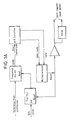
- the arrangement comprises a reference oscillator 1, the output of which is applied in parallel to two synthesisers 2 and 3.
- the first synthesiser 2 has an output at 1 GHz and is used to drive a shift register 4 which generates a first pseudo-random noise code PN1, also referred to as the transmit code, at its output 5.
- the output of the second synthesiser 3 has an output of 1 GHz offset by 1 kHz which is applied to a second shift register 6.
- the second shift register 6 is identical to the first shift register 4 and generates a second pseudo-random noise code PN2 at its output, also referred to as the receive code, which has an identical pattern to PN1 but which is clocked at a faster rate.
- the output signals of the first and second shift registers 4 and 6 produce code patterns whose alignment slowly changes with time. When the offset is as shown at 1kHz this results in the codes slipping by one chip length (1 ns) per millisecond.
- the outputs of the shift registers 4 and 6 are combined at an exclusive OR gate 8 the output of which is transmitted via a low pass filter 9 and a comparator 10 to a timing logic circuit 11, shown schematically in Figure 1A.
- the exclusive OR gate 8 gives a detectable output at the instant when the codes are in perfect alignment and this is used to provide an accurate time zero reference for the timing logic circuit 11.
- the A/D sampling clock from circuit 11 is synchronised to the pulse which indicates when the shift registers 4 and 6 are in coincidence.
- Figure 2 shows a section of the PN waveforms with varying delay.
- the transmit code PN1 appears at a on Figure 1 and waveforms (i) to (iv) appear at b and represent the received code PN2 sliding relative to PN1 with time.
- the variation of the filtered output from the exclusive OR gate 8 is the triangular peak shown in Figure 3.
- the receive code PN2 is in advance of the transmit code PN1 by more than a code clock period so the filtered output of the exclusive OR gate 8 is zero.
- Case (ii) shows the receive code PN2 half a clock period ahead of the transmit code PN1, which gives a 50% filtered output.
- the filtered output is at its peak, and falls linearly until the codes reach condition (iv) where the receive code PN2 is one clock period later than the transmit code PN1.
- the code length of PN 1 and PN 2 is determined by the dynamic range of signals which must be simultaneously coped with. There is always a large return from zero range because of the reflection coefficient of the horn 17. Outside of one chip length from zero range, the effect of this is attenuated by a factor equal to the code length. If the wanted return is attenuated by up to 70dB and the return loss of the horn can be as poor as 10dB then the direct signal from the horn could be up to 60dB larger than the wanted signal.
- the microwave signal to be transmitted is derived from a 10 GHz oscillator 12, one output which is applied to a mixer 13 wherein it is mixed with an IF frequency at 7.5 kHz from a source 14 to give a double sideband signal. This is then applied to a double balanced mixer 15 where it is mixed with the transmit code PN1 from the first shift register 4 to produce a spread spectrum signal.
- the mixer diodes of mixer 15 are switched by the PN1 signal providing a rectangular form to the PN modulation to give good system resolution.
- the spread spectrum signal is transmitted by a circulator 16 and radiated from a transmit/receiver horn antenna 17.
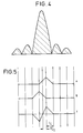
- the modulated PN signal shown at c of Figure 1 has a spectrum comprising closely spaced spectral lines with a sin (x)/x envelope as shown in Figure 4. This is centred on 10GHz with the nulls at multiples of 1GHz either side. If a single carrier without the IF offset were used then the individual spectral lines would be spaced by the repeat rate of the code, i.e. 1GHz ⁇ 32767 giving 30kHz approximately. Since a double sideband carrier is used, however, the actual spectrum at c consists of two such spectra superimposed, one at an IF frequency below 10GHz and the other at an IF frequency above 10GHz.
- the transmitted microwave signal is reflected and received at the horn 17.
- the received signal is passed via the circulator 16 to another mixer 18 where it is mixed with the receive code PN2 having the same sequence as the transmitted code PN1 and sliding in time with respect to it.
- the output of the mixer 18 is a replica of the double sideband signal which fed the transmit PN modulator 15.
- the output of the mixer 18 is applied to another mixer 19 which is mixed with the output of the oscillator 12 to give a return at 7.5 kHz.
- This ac signal from the mixer 19 is applied via a bandpass filter 20 at 7.5 kHz and applied to a variable gain amplifier 21, the output of which is applied to a simple rectifier circuit 22 for detection via a linear AM demodulator.
- the output of the detector 22 at d on Figure 1 follows a similar curve as that shown in Figure 3 as the receive reference code passes through alignment with the delayed transmit code.
- the signal is digitised by an analogue to digital converter 23 and stored in a memory 24 for subsequent processing at 25.
- the frequency offset between the codes PN1 and PN2 results in reflections separated by lns in the microwave signal (ie 150mm of range) appearing as peaks 1ms apart at the receiver output.
- the variation of the receiver output amplitude with time maps the microwave reflections versus range on a scale of 150 mm per ms.
- the data therefore arrives at a rate at which it can be easily digitised and stored. Fairly simple digital processing is required to identify the required return and accurately estimate its time of arrival.
- the accuracy of the time calibration is directly dependent on the frequency difference between the two PN code clocks which are therefore synthesised from a common crystal derived reference oscillator 1.
- the shift registers 4 and 6 are reset by signals on lines 27 and 28 respectively from the timing logic circuit 11.
- the shift registers are set to state such that the measurement is recommenced from a slightly negative range.
- the shift register 4 and 6 produce codes which are slightly out of alignment and then a short time later come into alignment. This ensures that the zero reference pulse is produced from the exclusive OR gate 8.
- the processor circuit 25 is responsible for both transferring the data from the analogue to digital converter 23 to the memory 24 and for analysing the data and so producing an output of the time of the required return.
- An IF attenuator 21 is under the control of the processor to maintain the signal at a suitable level.
- the processor circuit 25 On power up reset, the processor circuit 25 also programs the synthesiser chip 2 and 3 to give the desired division ratios.
- the processor circuit 25 When it is ready for a new measurement cycle, the processor circuit 25 send a reset pulse to timing circuitry 11. This sends a pulse to the shift registers 4 and 6 which clears them and resets the divider for the A to D sampling clock. The A to D sampling clock is recommenced on arrival of a sync pulse, indicating range zero and derived ultimately from the exclusive OR gate 8. The processor circuit 25 waits for a status signal from the A to D converter to indicate that data is ready. The data is then transferred from the A to D converter 23 to the memory 24. Further data is similarly collected until sufficient samples have amassed to cover the whole 30m of range.
- the IF attenuation value is changed by a control signal on line 29 from the processor 25 and the measurement is restarted.
- the desired peak is searched for. Normally, this will be close to the peak found on the previous measurement, so that the search starts in that region. The exact location of the peak is found by interpolation between samples.
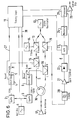
- Figure 5 shows how a difference curve can be used to accurately estimate the position of the peak.
- Trace “b” represents the samples from one clock period earlier than trace "a”.
- Trace “c” is generated by substracting trace “b” from trace “a”. It can be seen that trace “c” crosses zero at a point mid-way between the peaks of traces “a” and "b". This zero crossing can be found accurately by interpolation, even if the peaks of the traces fall between sampling points.
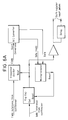
- FIG. 6 and 6A Another embodiment of the invention is shown in Figures 6 and 6A. This is similar to the arrangement of Figure 1, like references being used for like parts, but in this case the exclusive OR gate from which a synchronising pulse is derived has been omitted. Since the shift registers 4 and 6 are reset by the timing circuitry 11, it is not necessary to derive a synchronising pulse if it can be guaranteed that the shift registers are reset at exactly the same relative time each measurement. Since the actual timing of the shift register changing state is synchronised to its clock, this implies that the 1GHz clock and the 1GHz + 1kHz clocks must be in the same relative phase at the time of reset. The relative phase of the two clocks changes in step with the 1kHz difference frequency which is available from the frequency synthesisers 2 and 3.
Landscapes
- Physics & Mathematics (AREA)
- Engineering & Computer Science (AREA)
- Radar, Positioning & Navigation (AREA)
- Remote Sensing (AREA)
- Electromagnetism (AREA)
- General Physics & Mathematics (AREA)
- Thermal Sciences (AREA)
- Fluid Mechanics (AREA)
- Computer Networks & Wireless Communication (AREA)
- Radar Systems Or Details Thereof (AREA)
Applications Claiming Priority (2)
| Application Number | Priority Date | Filing Date | Title |
|---|---|---|---|
| GB9225782 | 1992-12-10 | ||
| GB929225782A GB9225782D0 (en) | 1992-12-10 | 1992-12-10 | Distance measuring arrangement |
Publications (2)
| Publication Number | Publication Date |
|---|---|
| EP0601884A2 true EP0601884A2 (de) | 1994-06-15 |
| EP0601884A3 EP0601884A3 (de) | 1994-12-14 |
Family
ID=10726389
Family Applications (1)
| Application Number | Title | Priority Date | Filing Date |
|---|---|---|---|
| EP93309998A Withdrawn EP0601884A3 (de) | 1992-12-10 | 1993-12-10 | Entfernungsmessvorrichtung. |
Country Status (3)
| Country | Link |
|---|---|
| EP (1) | EP0601884A3 (de) |
| GB (2) | GB9225782D0 (de) |
| NO (2) | NO934527D0 (de) |
Cited By (7)
| Publication number | Priority date | Publication date | Assignee | Title |
|---|---|---|---|---|
| WO2001061287A1 (de) * | 2000-02-17 | 2001-08-23 | Endress + Hauser Gmbh + Co. Kg | Verfahren und vorrichtung zur bestimmung des füllstandes eines füllguts in einem behälter |
| DE10307542A1 (de) * | 2002-11-27 | 2004-06-17 | Fibotec Fiberoptics Gmbh | Verfahren und Anordnung zur Ermittlung von Verluststellen in optischen Fasern |
| AT413889B (de) * | 2003-05-08 | 2006-07-15 | Kreuzgruber Gmbh | Verfahren und einrichtung zur abstandsmessung zwischen zwei sendeempfängern |
| US7199751B2 (en) * | 2004-06-14 | 2007-04-03 | Fujitsu Limited | Radar equipment |
| EP1777547A1 (de) * | 2005-10-24 | 2007-04-25 | Mitsubishi Electric Information Technology Centre Europe B.V. | Signalverarbeitung und Zeitverzögerungsmessung die auf eine Kombination von Korrelation und differential Korrelation basiert sind |
| US8115672B2 (en) * | 2010-02-02 | 2012-02-14 | Thales | Method of measuring distance, notably for short-range radar |
| CN105157789A (zh) * | 2015-05-15 | 2015-12-16 | 中国科学院沈阳自动化研究所 | 一种高精度测量的雷达物位计 |
Families Citing this family (1)
| Publication number | Priority date | Publication date | Assignee | Title |
|---|---|---|---|---|
| DE102010027962A1 (de) * | 2010-04-20 | 2011-10-20 | Endress + Hauser Gmbh + Co. Kg | Füllstandsmessgerät |
Family Cites Families (6)
| Publication number | Priority date | Publication date | Assignee | Title |
|---|---|---|---|---|
| FR2327553A1 (fr) * | 1975-10-10 | 1977-05-06 | Thomson Csf | Dispositif de mesure par correlation electronique du retard entre deux signaux temporels et systemes comportant un tel dispositif |
| US4325138A (en) * | 1980-09-29 | 1982-04-13 | Sperry Corporation | Continuous wave adaptive signal processor system |
| US4429310A (en) * | 1981-04-22 | 1984-01-31 | Sperry Corporation | Random binary waveform encoded ranging apparatus |
| CA2036779A1 (en) * | 1990-02-26 | 1991-08-27 | Akio Nagamune | In-furnace level meter and antenna therefor |
| CA2038818A1 (en) * | 1990-03-30 | 1991-10-01 | Akio Nagamune | Distance measuring method and apparatus therefor |
| CA2038825A1 (en) * | 1990-03-30 | 1991-10-01 | Akio Nagamune | In-furnace slag level measuring apparatus |
-
1992
- 1992-12-10 GB GB929225782A patent/GB9225782D0/en active Pending
-
1993
- 1993-12-10 NO NO934527D patent/NO934527D0/no unknown
- 1993-12-10 EP EP93309998A patent/EP0601884A3/de not_active Withdrawn
- 1993-12-10 GB GB9325327A patent/GB2273409A/en not_active Withdrawn
- 1993-12-10 NO NO934527A patent/NO934527L/no unknown
Cited By (10)
| Publication number | Priority date | Publication date | Assignee | Title |
|---|---|---|---|---|
| WO2001061287A1 (de) * | 2000-02-17 | 2001-08-23 | Endress + Hauser Gmbh + Co. Kg | Verfahren und vorrichtung zur bestimmung des füllstandes eines füllguts in einem behälter |
| US6930632B2 (en) | 2000-02-17 | 2005-08-16 | Endress + Hauser Gmbh + Co. Kg | Method and device for determining the level of a filling in a container |
| DE10307542A1 (de) * | 2002-11-27 | 2004-06-17 | Fibotec Fiberoptics Gmbh | Verfahren und Anordnung zur Ermittlung von Verluststellen in optischen Fasern |
| AT413889B (de) * | 2003-05-08 | 2006-07-15 | Kreuzgruber Gmbh | Verfahren und einrichtung zur abstandsmessung zwischen zwei sendeempfängern |
| US7199751B2 (en) * | 2004-06-14 | 2007-04-03 | Fujitsu Limited | Radar equipment |
| EP1777547A1 (de) * | 2005-10-24 | 2007-04-25 | Mitsubishi Electric Information Technology Centre Europe B.V. | Signalverarbeitung und Zeitverzögerungsmessung die auf eine Kombination von Korrelation und differential Korrelation basiert sind |
| WO2007049023A1 (en) * | 2005-10-24 | 2007-05-03 | Mitsubishi Electric Information Technology Centre Europe B.V. | Signal processing and time delay measurement based on combined correlation and differential correlation |
| US8115672B2 (en) * | 2010-02-02 | 2012-02-14 | Thales | Method of measuring distance, notably for short-range radar |
| CN105157789A (zh) * | 2015-05-15 | 2015-12-16 | 中国科学院沈阳自动化研究所 | 一种高精度测量的雷达物位计 |
| CN105157789B (zh) * | 2015-05-15 | 2018-03-20 | 中国科学院沈阳自动化研究所 | 一种高精度测量的雷达物位计 |
Also Published As
| Publication number | Publication date |
|---|---|
| GB9325327D0 (en) | 1994-02-16 |
| NO934527L (no) | 1994-06-13 |
| EP0601884A3 (de) | 1994-12-14 |
| NO934527D0 (no) | 1993-12-10 |
| GB2273409A (en) | 1994-06-15 |
| GB9225782D0 (en) | 1993-02-03 |
Similar Documents
| Publication | Publication Date | Title |
|---|---|---|
| EP0138940B1 (de) | Verfahren und vorrichtung zum messen des abstandes bis zu einem gegenstand | |
| RU2419813C2 (ru) | Устройство измерения расстояния и способ измерения расстояния | |
| US4403857A (en) | Distance measuring device and method | |
| US4078234A (en) | Continuous wave correlation radar system | |
| EP0351156B1 (de) | Ortungsempfänger vom Typ GPS mit Radiofrequenzteil und Datenverarbeitungsteil | |
| KR100675193B1 (ko) | 거리를 측정하기 위한 트랜스폰더 시스템 및 방법 | |
| JPH02504673A (ja) | ナビゲーション及びトラッキングシステム | |
| US3128465A (en) | Timing synchronization by radio frequency communication | |
| EP0449590A2 (de) | Gerät zum Messen des Schlackenniveaus in einem Ofen | |
| US3530470A (en) | Radio ranging system | |
| US9134406B2 (en) | Method and device for measuring a change in distance | |
| EP2444818A1 (de) | Impulsechomesssystem und -verfahren | |
| EP0601884A2 (de) | Entfernungsmessvorrichtung | |
| CN109632043B (zh) | 借助连续波雷达测量确定介质料位的方法和料位测量设备 | |
| US3613095A (en) | Method of and apparatus for locating a position | |
| JP2001509264A (ja) | レーダー距離計 | |
| US4301455A (en) | Groundspeed measurement system | |
| US3816832A (en) | Radio receiving station | |
| EP0048170B1 (de) | Reichweitebestimmungs-Radarsystem | |
| US3242492A (en) | Radiolocation systems | |
| US3797015A (en) | Method of and system for locating a position | |
| US4449209A (en) | Utilization of entire transmitted bandwidth in continuous transmission FM sonar | |
| US4325067A (en) | Method and apparatus for removing noise in a LORAN-C navigation receiver | |
| US7046345B2 (en) | Apparatus for precise distance measurement | |
| US3790940A (en) | Communication apparatus having a ranging capability |
Legal Events
| Date | Code | Title | Description |
|---|---|---|---|
| PUAI | Public reference made under article 153(3) epc to a published international application that has entered the european phase |
Free format text: ORIGINAL CODE: 0009012 |
|
| AK | Designated contracting states |
Kind code of ref document: A2 Designated state(s): NL SE |
|
| PUAL | Search report despatched |
Free format text: ORIGINAL CODE: 0009013 |
|
| AK | Designated contracting states |
Kind code of ref document: A3 Designated state(s): NL SE |
|
| STAA | Information on the status of an ep patent application or granted ep patent |
Free format text: STATUS: THE APPLICATION IS DEEMED TO BE WITHDRAWN |
|
| 18D | Application deemed to be withdrawn |
Effective date: 19950615 |