EP0601940B1 - Magnetaufzeichnungskanal eines nicht idealen gleichstromfreien Entzerrers und einem gleichstromfreien Modulationskode - Google Patents
Magnetaufzeichnungskanal eines nicht idealen gleichstromfreien Entzerrers und einem gleichstromfreien Modulationskode Download PDFInfo
- Publication number
- EP0601940B1 EP0601940B1 EP93420478A EP93420478A EP0601940B1 EP 0601940 B1 EP0601940 B1 EP 0601940B1 EP 93420478 A EP93420478 A EP 93420478A EP 93420478 A EP93420478 A EP 93420478A EP 0601940 B1 EP0601940 B1 EP 0601940B1
- Authority
- EP
- European Patent Office
- Prior art keywords
- response
- pulse
- equalizer
- code
- binary data
- Prior art date
- Legal status (The legal status is an assumption and is not a legal conclusion. Google has not performed a legal analysis and makes no representation as to the accuracy of the status listed.)
- Expired - Lifetime
Links
- 230000004044 response Effects 0.000 claims description 140
- 230000007704 transition Effects 0.000 claims description 27
- 238000000034 method Methods 0.000 claims description 20
- 230000001364 causal effect Effects 0.000 claims description 9
- 238000001514 detection method Methods 0.000 description 20
- 238000013461 design Methods 0.000 description 17
- 238000007476 Maximum Likelihood Methods 0.000 description 13
- 230000006870 function Effects 0.000 description 10
- 230000001939 inductive effect Effects 0.000 description 9
- 238000005070 sampling Methods 0.000 description 7
- 238000012546 transfer Methods 0.000 description 6
- 230000008901 benefit Effects 0.000 description 5
- 230000008569 process Effects 0.000 description 5
- 241000111471 Convolvulus scoparius Species 0.000 description 3
- 230000003044 adaptive effect Effects 0.000 description 3
- 238000013459 approach Methods 0.000 description 3
- 230000015572 biosynthetic process Effects 0.000 description 3
- 238000004891 communication Methods 0.000 description 3
- 230000009977 dual effect Effects 0.000 description 3
- 230000006872 improvement Effects 0.000 description 3
- 238000012545 processing Methods 0.000 description 3
- 230000011664 signaling Effects 0.000 description 3
- 230000002596 correlated effect Effects 0.000 description 2
- 239000010432 diamond Substances 0.000 description 2
- 230000004069 differentiation Effects 0.000 description 2
- 230000010354 integration Effects 0.000 description 2
- 238000005457 optimization Methods 0.000 description 2
- 230000035945 sensitivity Effects 0.000 description 2
- 238000001228 spectrum Methods 0.000 description 2
- 238000003786 synthesis reaction Methods 0.000 description 2
- 229910000859 α-Fe Inorganic materials 0.000 description 2
- 239000008186 active pharmaceutical agent Substances 0.000 description 1
- 230000032683 aging Effects 0.000 description 1
- 239000002131 composite material Substances 0.000 description 1
- 238000005094 computer simulation Methods 0.000 description 1
- 230000000875 corresponding effect Effects 0.000 description 1
- 238000013500 data storage Methods 0.000 description 1
- 230000007423 decrease Effects 0.000 description 1
- 238000011161 development Methods 0.000 description 1
- 230000018109 developmental process Effects 0.000 description 1
- 238000010586 diagram Methods 0.000 description 1
- 230000000694 effects Effects 0.000 description 1
- 230000008030 elimination Effects 0.000 description 1
- 238000003379 elimination reaction Methods 0.000 description 1
- 238000005516 engineering process Methods 0.000 description 1
- 230000002452 interceptive effect Effects 0.000 description 1
- 238000004377 microelectronic Methods 0.000 description 1
- 238000012797 qualification Methods 0.000 description 1
- 238000011084 recovery Methods 0.000 description 1
- 230000003595 spectral effect Effects 0.000 description 1
- 239000000126 substance Substances 0.000 description 1
- 230000002123 temporal effect Effects 0.000 description 1
- 239000010409 thin film Substances 0.000 description 1
- 230000001131 transforming effect Effects 0.000 description 1
Images


Classifications
-
- G—PHYSICS
- G11—INFORMATION STORAGE
- G11B—INFORMATION STORAGE BASED ON RELATIVE MOVEMENT BETWEEN RECORD CARRIER AND TRANSDUCER
- G11B20/00—Signal processing not specific to the method of recording or reproducing; Circuits therefor
- G11B20/10—Digital recording or reproducing
- G11B20/14—Digital recording or reproducing using self-clocking codes
- G11B20/1403—Digital recording or reproducing using self-clocking codes characterised by the use of two levels
- G11B20/1423—Code representation depending on subsequent bits, e.g. delay modulation, double density code, Miller code
- G11B20/1426—Code representation depending on subsequent bits, e.g. delay modulation, double density code, Miller code conversion to or from block codes or representations thereof
-
- G—PHYSICS
- G11—INFORMATION STORAGE
- G11B—INFORMATION STORAGE BASED ON RELATIVE MOVEMENT BETWEEN RECORD CARRIER AND TRANSDUCER
- G11B20/00—Signal processing not specific to the method of recording or reproducing; Circuits therefor
- G11B20/10—Digital recording or reproducing
- G11B20/10009—Improvement or modification of read or write signals
Definitions
- This invention relates to data recording and retrieval of data stored in magnetic data storage systems.
- the present invention provides improved linear density of data stored in systems by employing (1+ D ) n Partial Response (PR) equalization.
- PR Partial Response
- the invention can be used with Maximum Likelihood (ML) detection but can also be used with other detection systems.
- Peak detectors were almost universally employed in digital magnetic recording systems prior to introduction of a disk drive employing PR4 equalization with sampling Viterbi detection by IBM in 1990.
- the purpose of the peak detector is to detect recorded digital data ("0"s and "1”s) as it passes the read head.
- a "1" appears as a readback pulse with a single peak and a "0” as the absence of a pulse in a predetermined time slot, or "bit cell” or “window”. Since pulse peaks are somewhat indistinct by their nature, peak detectors operate by transforming peaks into zero-crossings, which are more easily detectable events.
- Two types of peak detector channels are in common use - namely 1) the differentiating amplitude-qualified peak detector (AQPD), and 2) the integrating detector.
- isolated pulse (or step response) 100 for an unshielded magnetoresistive (UMR) head is equalized if needed to be bounded in time, and then differentiated to provide the zero-crossing event.
- Equalized pulse 102 for the UMR head has gradual undershoot features 12 and 14, which is absent with inductive heads.
- Differentiated pulse 104 provides the desired zero-crossing event.
- Most of the equalized pulse energy is in the ⁇ - T min , T min ⁇ interval, where T min is the minimum time between transitions.
- the signal in an AQPD channel may have false peaks due to the shape and/or the presence of noise in the "shoulder" regions 21 of equalized signal 110.
- the equalized (undifferentiated) signal amplitude must be greater than a threshold, which is typically set around half the average peak (envelope) amplitude. Often the threshold is set a little lower in the presence of modulation noise.
- An AQPD involves the coincident operation of two channels known as the amplitude and timing channels.
- Feature 28 of differentiated peak detector signal 120 illustrates a qualified zero crossing.
- a relevant patent for this type of detector is U.S. Patent 4,081,756, "Dual Channel Signal Detector Circuit", by R. Price et al., issued Mar. 28, 1978, which describes a peak detection channel that senses the peaks of the read signal and a simultaneously operating gate generating channel that produces gating pulses in response only to individual read pulses in the read signal.
- the isolated pulse 200 is also equalized if needed to be bounded in time (pulse 202), and then integrated (pulse 204) to provide the desired zero-crossing event.
- the integration must be imperfect (represented by a pole on the negative real axis near the origin) to avoid excessive low frequency noise enhancement.
- the imperfect integration results in a droop in the isolated pulse response, which is illustrated at feature 32 of integrated pulse 204.
- Integrating detectors must be used with encoded data having codes that have d.c.-free write current or with decision feedback equalization (DFE) in order to avoid excessive baseline shift due to intersymbol interference (ISI) from distant neighbors.
- DFE decision feedback equalization
- baseline shift in signal 220 appears as a slow variation in the location of signal samples at the clock time, i.e., the diamonds near the baseline. Since the signals in integrating detectors do not approach zero between peaks, amplitude qualification is not needed, and, therefore, integrating detectors require only one channel, the timing channel, for the decision process.
- Run Length Limited (RLL) codes for encoding data are defined from the viewpoint of NRZI, where for each bit cell, a "1" represents a recorded magnetic transition, and "0" represents no transition.
- the run length constraints can be described alternately as a minimum of d +1 and a maximum of k +1 clock intervals between recorded transitions.
- the minimum time between transitions is T min ( d +1) T C .
- the detection window, T W is equal to T C .
- the purpose of RLL codes is to make the code self-clocking by limiting the maximum run of "0"s, and sometimes (but not always) to increase T min to a value greater than T d .
- a readback pulse peak detected anywhere within a window is assumed to have been written at the center of that window.
- the sign of the write current alternates at each transition.
- a transition spacing of s contributes to ⁇ s to the accumulated charge.
- the example below shows the accumulated charge of a (1,7) RLL data pattern: SPACING s 4 2 3 2 2 5 8 2 2 4 polarity + - + - + - + - + - + - + - - - - - - CHARGE 4 2 5 3 5 0 8 6 8 4
- (1,7) CCRLL code rates would have to be 5/8 or 3/5 (0.625 or 0.6), depending on c .
- CCRLL codes are used in magnetic recording systems with rotary transformers, which cannot pass d.c. in the write current.
- CCRLL codes can be difficult to design, especially at code rates close to the capacity. Procedures for their design are familiar to coding specialists in this field.
- Equalizers for peak detectors are designed to minimize ISI so that each peak may be discretely detected. Such equalizers are sometimes called “zero forcing" equalizers. At worst, a small amount of ISI is tolerated due to the tradeoff between slimming and high frequency noise enhancement.
- Partial Response (PR) equalizers employ deliberate ISI to reduce the high frequency noise enhancement. This makes the channel more closely resemble the matched filter, improving the equalized pulse signal-to-noise ratio (SNR).
- PR equalization is used with maximum likelihood (ML) detectors, whose function is to separate optimally the data out of the deliberately overlapping or interfering pulses. ML detectors sample the signal at discrete times which are not necessarily tied to specific events such as peaks.
- PRML PRML
- the Viterbi detector is the best known ML detector for use with PR equalization.
- the terms "Viterbi” and “ML” are sometimes used interchangeably.
- PRML was first proposed for magnetic recording systems by Kobayashi and Tang of IBM in 1970 and 1971. See H. Kobayashi and D. Tang, “Application of Partial-Response Channel Coding to Magnetic Recording Systems", IBM Jrnl. of Res. & Dev., vol. 14, no. 4, July, 1970, p. 368; and H. Kobayashi, "Application of Probalistic Decoding to Digital magnetic Recording Systems", IBM Jrnl. of Res. & Dev., vol.
- Peak detection recording systems are generally characterized by their isolated pulse or step response (response to the NRZI ...0001000... pattern, where "1" is a transition and "0" is no transition). This is their response to a single recorded transition.
- PRML systems by contrast, are characterized by their equalized pulse response (response to the NRZ ...0001000... pattern, equivalent to NRZI ...00011000%), where the write pulse consists of two write current steps (or recorded transitions) separated by the clock period, T .
- NRZI recording is in fact a type of precoding, which is discussed elsewhere in this specification, performed on NRZ data to minimize error propagation in peak detection channels. The use of the pulse response facilitates the description of the system state for the ML detector and eliminates the need to keep track of the alternating signs of the NRZI transitions.
- the pulse response polynomial is equivalent to the expected pulse response at sampling times, i.e. bit cells.
- the expected pulse response at the sampling times is ...000-101000...
- the PR4 isolated pulse peak is located between the two nonzero sampling points, i.e., the PR4 signal is sampled on non-events off the peaks. Because of this sampling parameter, timing recovery for PR systems must be performed by sophisticated digital techniques, as described in Dolivo (supra), or by a separate analog timing channel.
- 1/2 T , and beyond this frequency.
- Practical peak detection systems with analog equalization operate with considerable excess bandwidth and trade off pulse slimming with noise enhancement.
- the (1- D ) term arises from the differentiation in the read process for inductive heads or the sensitivity to the perpendicular field in magnetoresistive heads.
- the PR channels previously discussed in magnetic recording literature contain the (1- D ) pulse response term.
- One exception is described in R. Wood, "New Detector for 1,k Codes Equalized to Class II Partial Response", IEEE Trans. Magn., vol. MAG-25, no. 5, September 1989, p. 4075, which describes a PR2 channel for a (1,k) code that uses a type of decision feedback called a "Modified Linear Canceler" that does not resemble the present invention.
- the standard PR precoding algorithm is the 1/ F '( D ) operation on the NRZ encoded bit pattern, where F '( D ) is the expanded response polynomial F ( D ) with + and - replaced by the (+ mod 2) or XOR operator. This replacement results in even output levels for code "0"s and odd output levels for code "1"s, eliminating error propagation.
- the precoder is a conventional element of PRML systems, and is discussed in detail in the classic papers on PRML.
- modulation codes for PR systems must be designed to eliminate long runs of this pattern, in a manner similar to the elimination of long runs of the NRZ ...0000... and NRZ ...1111... patterns (both equivalent to long runs of NRZI "0"s).
- PR channels are arbitrary labels of no particular significance which were originated in E. Kretzmer's "Generalization of a Technique for Binary Data Communication", IEEE Trans. Commun. Techn., vol. COM-14, Feb. 1966, p. 67. PARTIAL RESPONSE SYSTEMS Name Pulse Response Polynomial F ( D ) No. of Levels No. of States % Speed Tolerance Min.
- the speed tolerance and eye pattern width which are both measures of timing sensitivity, are taken from Kabal and Pasupathy (supra).
- the (1- D ) factor in F ( D ) eliminates the d.c. content of partial response signals. D.C. content is present in PR1 and PR2 signals, neither of which contain the (1- D ) factor.
- PR1 and PR2 equalization is intended for use in communication channels other than magnetic recording systems that can support d.c. signals. Thus, these other channels are neither strictly analogous to nor considered useful in the art of magnetic recording.
- the prior art of magnetic recording teaches that the (1- D ) factor must be present in the partial response polynomial.
- a magnetic recording channel can be treated as a partial-response channel that possesses an inherent factor (1- D ) in its discrete transfer function
- H. Kobayashi and D. Tang "The 1- D factor is included in the channel transfer function of magnetic recording systems because of the inherent differentiation in the playback process," J. Moon and L. R. Carley.
- class-IV signaling (PR-IV) with polynomial 1- D 2 and extended class-IV (EPR-IV) with polynomial 1+ D - D 2 - D 3 exhibit spectral nulls at DC and at half the signaling rate.
- the input to a Viterbi detector is sampled data, which is usually digitized.
- the operation of a Viterbi detector is usually visualized by means of the Viterbi trellis, illustrated in Figures 5, 6 and 7 for PR2, PR2, and PR4 equalization, respectively.
- the state of the system is the contents of a memory contained within the Viterbi detector whose size is determined by the number of samples, L , over which the response is spread. There are 2 L-1 states, derived from the L -1 samples prior to the present sample, which is not a part of the state (i.e., memory).
- the expected sample value E ( D ) or "transition" ( Figure 5) is derived from the PR polynomial, F ( D ) .
- the Viterbi detector Starting with a known state (a node on the Viterbi trellis), the Viterbi detector compares each data sample with the expected transition on the trellis for each path starting at that state, calculating and storing the square metric (the sum of the squares of the difference between the samples and the expected transitions) for each path on the trellis. Whenever more than one path enters a node, the one with the worst metric is eliminated. Where there is only one surviving path leaving the starting node, a decision has been made. In actual Viterbi detectors, this algorithm is simplified to reduce the detection process to a sequence of add, compare, and select operations in order to minimize hardware complexity. These simplifications do not alter the substance of the algorithm.
- Viterbi detector for any of the above referenced PR equalizations can be accomplished by an engineer versed in the art of digital circuit design. See, for example, R. Wood and D. Petersen, "Viterbi Detection of Class IV Partial Response on a Magnetic Recording Channel", IEEE Trans. Commun., vol. COM-34, no. 5, May 1986, p. 493.
- the performance improvement over symbol-by-symbol detection is largely determined by the minimum distance error event, which is the difference between any pair of paths starting and ending at the same node that has the minimum squared distance metric d min 2 (the sum of squares of the differences between expected transitions). These paths are illustrated by the pairs of dashed paths in Figures 5, 6 and 7.
- d min 2 2 .
- d min 2 4.
- the effective SNR improvement of the Viterbi detector is 10 log 10 ( d min 2 ), or and 3 dB for PR1 and PR4 and 6 dB for PR2 and EPR4. This equation assumes white (uncorrelated) noise at the Viterbi detector input.
- the minimum distance error event results from one of two situations: a missing (or added) bit, e.g., 00000 vs. 00100; or a shifted bit, e.g., 001000 vs. 000100.
- the two dashed paths illustrated for PR2 in Figure 7 represent data 0001000 and 0010000, i.e., a shifted bit error with a squared distance metric of 4.
- the squared distance metric for the missing bit error is 6.
- the noise at the Viterbi detector input is not generally white (uncorrelated).
- both the missing and shifted bit errors are immune to correlated noise.
- the shifted bit error is immune to correlated noise, but the missing bit error, which has a larger difference metric to begin with, may be highly sensitive.
- (1-D) (1+D) n equalizers such as PR4 and EPR4 are generally a better match to the pulse spectrum than peak detector equalizers, they may not be a good match at low frequencies, particularly for UMR heads, which have a high level of low frequency energy that is in effect thrown out by such equalizers.
- the present invention comprises a readback channel for digital magnetic recording systems which combines a d.c.-free equalizer to approximate the (1+ D ) n pulse response with a d.c.-free modulation code and comprises the elements described below.
- the prior art teaches that the intrinsic properties of the magnetic recording systems require the inclusion of the (1- D ) factor in the partial response polynomials. This factor is omitted in the present invention.
- the prior art also teaches that an equalizer should be designed for a pulse response that approximates the partial response polynomial as closely as possible, whereas the present invention calls for a deliberate deviation from that polynomial.
- the present invention with a modified R-DAT 8/10(0,3) CCRLL code and with an approximate d.c.-free PR2 equalizer, can provide very significant linear recording density increase over any known peak detection channel, as well as any of the PRML channels known in the prior art of magnetic recording, including PR4 and EPR4 channels.
- Document EP-A-0,250,049 discloses a channel encoder which generates DS free and run length limited m-bit (m-n) code words having (1- D ) -1 or (1+ D 2 ) -1 precoder properties. This prior art is reflected by the preambles of claims 1, 5 and 8.
- Figure 1 illustrates prior art AQPD step responses for (1, 7) code.
- Figure 2 illustrates prior art AQPD signals for (1, 7) code.
- Figure 3 illustrates prior art integrating detector step responses for (0, K) code.
- Figure 4 illustrates prior art integrating detector signals for (0, 3) CCRLL code.
- Figure 5 illustrates a partial response Viterbi trellis for a PR4 detector.
- Figure 6 illustrates a partial response Viterbi trellis for a PR1 detector according to the present invention.
- Figure 7 illustrates a partial response Viterbi trellis for a PR2 detector according to the present invention.
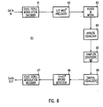
- FIG. 8 is a block diagram of digital magnetic recording system constructed according to the principles of the present invention.
- Figure 9 illustrates ideal PR2 detector pulse and step responses.
- Figure 10 illustrates integrating PR2 detector pulse and step responses.
- Figure 11 illustrates QI detector PR2 pulse and step responses.
- Figure 12 illustrates pulse responses for a UMR head equalizer design.
- Figure 13 illustrates a QI equalized PRI superimposed data pattern.
- Figure 14 illustrates a QI equalized PR2 superimposed data pattern.
- magnetic recording channel 80 constructed according to the principles of the present invention, comprise modulation encoder 81, precoder 82, recording heads and media 83, analog equalizer 84, sampler 85, detector 86 and modulation decoder 87.
- channel 80 may include digitizer 88 in phace of sampler 85 and digital equalizer 89.
- the D.C.-free approximate (1+ D ) n equalizer of the present invention is partitioned between analog and digital elements as described elsewhere in this specification.
- the design of the equalizer and detector elements of channel 80 are the subject of the present invention.
- the minimum bandwidth pulse response F PRn for ideal (1+ D ) n PR equalization is given the following frequency domain equation:
- the unequalized isolated pulse or step response G uneg ( ⁇ ) (i.e., the step response measured at the playback head) is finite at d.c.
- the pulse response for such is zero.
- Equation (2) indicates that such an unmodified equalizer would have infinite gain at d.c. This would result in disastrous enhancement of low frequency noise leading to an unacceptable rate of detection errors.
- the low frequency noise enhancement would result also in a gradual wander of the average signal level (the baseline), which could exceed the dynamic range of the analog-to-digital converter and/or the amplifier in the maximum likelihood detector.
- the present invention utilizes an equalizer having a response modified to have a pulse response of zero at d.c. and a step response that is finite at d.c.
- the pulse response is zero at d.c. while the step response is finite at d.c.
- the second equalizer target is suited for systems where a plurality of the unequalized pulse response energy is spread far beyond the ⁇ - T min , T min ⁇ region.
- Systems employing UMR and DMR heads fall into this category. These systems are also characterized by relatively high levels of long wavelength response. Because this equalizer resembles the integrating equalizer in certain respects, but differs from it in others, it has been named the quasi-integrating (QI) equalizer.
- QI equalizer for peak detection was described in a copending patent application, Serial No. 07/891,010, assigned to the assignee hereof.
- the QI equalizer pulse response F QI and step response G QI are given by the following equations:
- Both the pulse and step responses are zero at d.c.
- the pulse response is symmetrical while the step response is antisymmetrical.
- the QI equalizer is similar to the integrating equalizer except that its step response has a d.c. null and its pulse response is symmetrical rather than causal.
- the d.c. null is provided by a differentiator element which helps to attenuate undesirable low frequency noise.
- the equations for the integrating and QI targets are very similar, differing in just two significant respects: (a) the d.c. step response is zero for the QI target, while it is nonzero and finite for the integrating target, and (b) the step response is anti-symmetrical for the QI target, while it is causal for the integrating target.
- an equalizer is a linear network that shapes an unequalized input pulse into a desired output pulse.
- the equalizer of the present invention may be partitioned between analog and digital elements.
- the minimum requirement of the analog equalizer is that it functions as a low pass filter, which removes most of the noise above the Nyquist frequency (1/2T).
- the entire equalizer can be accomplished with analog circuitry, but for PR1, the very steep cosine high frequency rolloff cannot be attained with the limited number of elements practically attainable with analog circuitry. Since the Viterbi detector samples and normally digitizes the data, a digital equalizer is an obvious choice that can be implemented at little additional cost.
- the equalizer transfer function is expressed mathematically as the quotient of two polynomials in the complex (s) plane, where the roots of the numerator polynomial are known as "zeros", and the roots of the denominator polynomial are known as "poles".
- Equalizers represented by poles and zeros can be realized as RLC networks by using the techniques of circuit synthesis theory, well known to the art, and covered by such texts as "Circuit Synthesis and Design" by Gabor C. Temes and Jack W. LaPatra, published in 1977 by McGraw-Hill.
- Equalizer chips are now available that allow the pole and zero values to be programmed.
- An example of such a chip is the IMP 4250 Programmable Continuous-time Filter, in which up to six poles and six zeros can be programmed, available from International Microelectronic Products, of San Jose, CA.
- the prior art of analog equalizer design typically used the step response (isolated readback pulse) as its basis. Since the step response of an unshielded magnetic resistive head cannot be measured directly because of head saturation, the present equalizer design procedure is based on the pulse response, which does not saturate the UMR head. This procedure is also applicable to inductive heads.
- the length of the pulse is T 1 , which is normally the same as T or T min in the intended system. Any value of T 1 will do so long as it is short enough to avoid head saturation and long enough to provide adequate readback signal.
- the pulse response is derived by superposing two step responses of opposite polarity.
- Figure 1 feature 100
- Figure 11, feature 195 illustrates the QI equalized step response.
- the tails of both these pulses extend over a great many T min intervals.
- the experimental pulse response is digitally acquired (in a sampled array) by using an NRZI ..., T 2 , T 1 , T 2 , T 1 , T 2 ,...pattern, where T 2 >> T 1 , and T 2 is sufficiently large to guarantee an isolated pulse response.
- a simulated unequalized UMR pulse response is shown in Figure 12, feature 197.
- the QI equalizer can be very closely approximated with 7 poles and 3 zeros, where one of the zeros is a differentiator, i.e., it is fixed at the origin. The remaining two zeros, which are located on the positive and negative real axes, slim the pulse.
- the pole and zero values are obtained from a time domain optimizing program, which moves the poles and zeros (except for the differentiator, which is fixed) around the complex plane until the best least squares match between the equalizer output pulse response 198 and the target pulse response 199 is obtained for unequalized pulse 197.
- Subroutines to perform this type of computer optimization are found in a product called "The Optimization Toolbox for MATLAB", which is available from The Math Works, Natick, MA.
- the rise and fall time of the tails of the QI equalized pulse 196 (features 96 and 98 in Figure 11), which is inversely proportional to f L , normally approximates the rise and fall times respectively, of the input pulse 100 (features 16 and 18 in Figure 1).
- the integrating equalizer can be closely approximated with 8 poles and 2 zeros, where one of the poles is an imperfect integrator, located on the negative real axis close to the origin.
- the 7 pole, 3 zero equalizer output pulse response 198 strongly resembles the target 199.
- the number and location of the poles and zeros calculated by the optimization program are entered into a circuit synthesis program to complete the design of the actual RLC equalizer.
- Baseline shift in the QI and integrating detector signals results from intersymbol interference from neighboring pulses. Because of the large temporal spread of the pulses, this can include distant neighbors. In order to avoid excessive baseline shift, which could result in a significantly increased error rate, a charge constrained (d.c.-free) modulation code must be used in these channels.
- Run lengths of this pattern must be limited in order to limit the Viterbi detector memory.
- the R-DAT code is described by a lookup table, published in the "Recommended Design Standard, R-DAT" by the DAT Conference in April 1986.
- the 10 bit code is NRZI...1111111111. There is no limit of the repetition of this pattern.
- RLL codes have a maximum of three consecutive NRZI "0"s.
- An examination of the R-DAT lookup table reveals that relatively few 10 bit code patterns actually have three consecutive "0"s.
- An acceptable code for the ( 1 + D ) n channel can be generated by replacing the EB code pattern (NRZI 1111111111) with an unused code pattern containing three "0"s in a row that satisfies the charge constraint.
- NRZI 1100010001 is such a pattern. This replacement could be accomplished because the R-DAT code rate of 8/10 is well below the theoretical maximum of 0.8704 calculated by Norris and Bloomberg [1]. More optimum codes might further limit the NRZI 111111... run length.
- PR2 partial response type 2
- PR1 partial response type 2
- PR1 partial response type 2
- PR1 has two advantages over PR1 - namely, (1) for a specified error rate, it can operate at higher densities and (2) it has the cosine 2 high frequency rolloff, which is gradual enough to be reasonably approximated by analog equalizers.
- PR1 has the much more abrupt cosine high frequency rolloff, which cannot be adequately implemented with an analog equalizer. Such rolloff is a minor disadvantage since PRML systems operate on sampled data, making it relatively easy to implement digital equalization.
- PR1 has only three levels instead of five, and the Viterbi detector has only two states instead of four.
- Figures 13 and 14 illustrate the equalized response to the same R-DAT 8/10 (0,3) data pattern for QI equalized PR1 and QI equalized PR2 recording, respectively.
- the relative amplitude of high frequency pulses decreases in each figure: PR2 has the least high frequency content, accounting for much of its performance improvement.
- PR1 has three detection levels, i.e., expected samples indicated by diamonds, compared to five for PR2.
- any charge-constrained ( d , k ) RLL code can be used to enable the present invention.
- the pulse response is finite and non-zero at d.c.
- the step response is infinite at d.c.
- the pulse response is zero at d.c.
- the step response is zero at d.c. for the symmetrical target and finite and non-zero at d.c. for the causal target.
- the symmetrical target is generally appropriate for systems where the plurality of the unequalized pulse energy extends well beyond twice the minimum time between transitions, which typically includes systems with UMR and dual MR readback heads.
- the causal target is generally appropriate for systems where the plurality of the unequalized pulse energy is contained within approximately twice the minimum time between transitions, which typically includes systems with shielded MR and inductive readback heads.
- the causal target is appropriate for systems that employ decision feedback equalization (DFE) in their detector circuits.
- DFE decision feedback equalization
Landscapes
- Engineering & Computer Science (AREA)
- Signal Processing (AREA)
- Signal Processing For Digital Recording And Reproducing (AREA)
- Digital Magnetic Recording (AREA)
- Dc Digital Transmission (AREA)
Claims (9)
- Magnetische Aufzeichnungsvorrichtung (80) zum Speichern und Wiederauffinden binärer Daten, mitdadurch gekennzeichnet, daß das Entzerrmittel (84) ein Impulsansprechverhalten hat, das sich einem (1 + D) n Teilantwortpolynom nähert und bei Gleichstrom gleich null ist, um entzerrte Impulse in Abhängigkeit von den codierten binären Daten zu erzeugen.einem Codierer (81) zum Empfangen der die binären Daten darstellenden Signale und zum Codieren der binären Daten mit einem gleichstromfreien, ladungsgesteuerten Modulationscode, der durch die Zwangsbedingungen (d, k) für die Lauflänge gekennzeichnet ist;einem mit dem Codierer gekoppelten Entzerrmittel (84),einem mit dem Entzerrmittel gekoppelten Detektor (86) zum Erkennen der entzerrten Impulse undeinem mit dem Detektor gekoppelten Decoder (87) zum Decodieren der entzerrten Impulse,
- Vorrichtung nach Anspruch 1, dadurch gekennzeichnet, daß der Modulationscode beschränkt ist durch Begrenzen der Lauflänge von Codemustern, die für jede Taktperiode einen Übergang erfordern.
- Vorrichtung nach Anspruch 1, dadurch gekennzeichnet, daß das Entzerrmittel (84) ein antisymmetrisches Sprungantwortziel GQI und ein symmetrisches Impulsantwortziel FQI hat, die näherungsweise der Gleichung entprechen:wobei f = Frequenz, fc = abgeschnittene Frequenz bestimmt durch 1/T, wobei T die Taktperiode ist, und fL = eine in Verbindung mit den Anstiegund Abfallzeiten der Impulse stehende Frequenz.

- Vorrichtung nach Anspruch 1, dadurch gekennzeichnet, daß der Entzerrmittel (84) ein kausales Sprungantwortziel GINT und ein kausales Impulsantwortziel FINT hat, die näherungsweise der Gleichung entsprechen:wobei f = Frequenz, f c = abgeschnittene Frequenz bestimmt durch 1/T, wobei T die Taktperiode ist, und fL = eine in in Gegenbeziehung zu den Anstieg- und Abfallzeiten der Impulse stehende Frequenz.

- Verfahren zum Speichern und Wiederauffinden binärer Daten, mit den Schritten:dadurch gekennzeichnet, daß die entzerrten Impulse in Abhängigkeit von den codierten binären Daten gemäß einer Impulsantwort erzeugt werden, die sich einem (1 + D) n Teilantwortpolynom nähert und bei Gleichstrom gleich null ist.Empfangen der die binären Daten darstellenden Signale,Codieren der binären Daten mit einem gleichstromfreien, ladungsgesteuerten Modulationscode, der durch die Zwangsbedingungen (d, k) für die Lauflänge gekennzeichnet ist;Erzeugen entzerrter Impulse in Abhängigkeit von den codierten binären Daten,Erkennen der entzerrten Impulse undDecodieren der entzerrten Impulse,
- Verfahren nach Anspruch 5, dadurch gekennzeichnet, daß beim Codieren der Modulationscode beschränkt wird durch Begrenzen der Lauflänge von Codemustern, die für jede Taktperiode einen Übergang erfordern.
- Verfahren nach Anspruch 5, dadurch gekennzeichnet, daß die entzerrten Impulse gemäß einer Sprungantwort GQI und der Impulsantwort FQI erzeugt werden, wobei dies der Gleichung entspricht:wobei f = Frequenz, fC = abgeschnittene Frequenz bestimmt durch 1/T, wobei T die Taktperiode ist, und fL = eine in in Gegenbeziehung zu den Anstieg- und Abfallzeiten der Impulse stehende Frequenz.

- Verfahren zum Speichern und Wiederauffinden digitaler Daten, wobei die Daten darstellende Signale empfangen werden und die Daten mit einem gleichstromfreien, ladungsgesteuerten Modulationscode codiert werden, der durch die Zwangsbedingungen (d, k) für die Lauflänge gekennzeichnet ist; und wobei ertzerrte Impulse erzeugt werden, dadurch gekennzeichnet, daß die entzerrten Impulse in Abhängigkeit von den codierten Signalen gemäß einer entzerrten Impulsantwort erzeugt werden, die sich einem (1 + D) n Teilantwortpolynom nähert und bei Gleichstrom gleich null ist.
- Verfahren nach Anspruch 8, dadurch gekennzeichnet, daß beim Codieren der Modulationscode beschränkt wird, indem die Lauflänge von Codemustern begrenzt wird, die für jede Taktperiode einen Übergang erfordern.
Applications Claiming Priority (2)
| Application Number | Priority Date | Filing Date | Title |
|---|---|---|---|
| US989432 | 1992-12-11 | ||
| US07/989,432 US5550683A (en) | 1992-12-11 | 1992-12-11 | Magnetic recording channel employing a non-ideal d.c.-free equalizer and a d.c.-free modulation code |
Publications (2)
| Publication Number | Publication Date |
|---|---|
| EP0601940A1 EP0601940A1 (de) | 1994-06-15 |
| EP0601940B1 true EP0601940B1 (de) | 1998-07-22 |
Family
ID=25535108
Family Applications (1)
| Application Number | Title | Priority Date | Filing Date |
|---|---|---|---|
| EP93420478A Expired - Lifetime EP0601940B1 (de) | 1992-12-11 | 1993-12-01 | Magnetaufzeichnungskanal eines nicht idealen gleichstromfreien Entzerrers und einem gleichstromfreien Modulationskode |
Country Status (4)
| Country | Link |
|---|---|
| US (1) | US5550683A (de) |
| EP (1) | EP0601940B1 (de) |
| JP (1) | JPH06231546A (de) |
| DE (1) | DE69319864T2 (de) |
Cited By (1)
| Publication number | Priority date | Publication date | Assignee | Title |
|---|---|---|---|---|
| US8599959B2 (en) | 2010-12-30 | 2013-12-03 | Lsi Corporation | Methods and apparatus for trellis-based modulation encoding |
Families Citing this family (23)
| Publication number | Priority date | Publication date | Assignee | Title |
|---|---|---|---|---|
| US5424881A (en) * | 1993-02-01 | 1995-06-13 | Cirrus Logic, Inc. | Synchronous read channel |
| GB9324918D0 (en) * | 1993-12-04 | 1994-01-26 | Hewlett Packard Ltd | High-density data recording |
| US5768320A (en) * | 1995-09-05 | 1998-06-16 | Analog Devices, Inc. | Read system for implementing PR4 and higher order PRML signals |
| KR100213032B1 (ko) * | 1995-10-24 | 1999-08-02 | 윤종용 | 자기기록 재생장치에서 디지탈 신호 검출 장치 |
| US5708358A (en) * | 1996-03-21 | 1998-01-13 | Read-Rite Corporation | Spin valve magnetoresistive transducers having permanent magnets |
| US5786950A (en) * | 1996-07-29 | 1998-07-28 | Cirrus Logic, Inc. | PR4 sampled amplitude read channel employing an NRZI write modulator and a PR4/NRZI converter |
| US5872664A (en) * | 1996-12-06 | 1999-02-16 | Phase Metrics, Inc. | Distortion of an isolated pulse |
| US6163421A (en) * | 1997-09-05 | 2000-12-19 | Sony Corporation | Azimuth magnetic recording and reproducing apparatus and method employing waveform equalization |
| JP4092733B2 (ja) * | 1997-10-07 | 2008-05-28 | ソニー株式会社 | 磁気記録再生装置 |
| US6185716B1 (en) | 1998-01-30 | 2001-02-06 | Maxtor Corporation | Dual detector read channel with semi-soft detection |
| JP3776582B2 (ja) * | 1998-02-17 | 2006-05-17 | 富士通株式会社 | 記録再生装置 |
| JP2000306336A (ja) * | 1999-04-19 | 2000-11-02 | Sony Corp | 波形等化装置、波形等化装置の最適化方法、及びデータ再生装置 |
| JP3692961B2 (ja) * | 2001-04-13 | 2005-09-07 | ソニー株式会社 | 磁気記録データ再生装置及び方法 |
| US7127665B2 (en) * | 2001-10-03 | 2006-10-24 | Sony Corporation | Trellis code detector and decoder |
| US8650470B2 (en) * | 2003-03-20 | 2014-02-11 | Arm Limited | Error recovery within integrated circuit |
| KR100559730B1 (ko) * | 2003-09-22 | 2006-03-15 | 삼성전자주식회사 | 기록 시스템을 위한 데이터 부호화/복호화 방법 및 장치 |
| WO2005098855A1 (en) * | 2004-04-09 | 2005-10-20 | Koninklijke Philips Electronics N.V. | Modulation code system and methods of encoding and decoding a signal |
| US7719444B2 (en) * | 2007-11-16 | 2010-05-18 | International Business Machines Corporation | Modulation coding |
| US7974037B2 (en) * | 2008-02-21 | 2011-07-05 | Hitachi Global Storage Technologies Netherlands, B.V. | Techniques for providing DC-free detection of DC equalization target |
| WO2013063440A1 (en) * | 2011-10-27 | 2013-05-02 | Lsi Corporation | Vector processor having instruction set with vector convolution funciton for fir filtering |
| US8892986B2 (en) * | 2012-03-08 | 2014-11-18 | Micron Technology, Inc. | Apparatuses and methods for combining error coding and modulation schemes |
| CN114325846B (zh) * | 2021-11-18 | 2023-06-20 | 电子科技大学 | 一种利用时间相干性抑噪的磁异常检测方法 |
| CN116781464B (zh) * | 2023-08-22 | 2023-12-01 | 韬润半导体(无锡)有限公司 | 一种脉冲振幅调制的优化方法和系统 |
Family Cites Families (8)
| Publication number | Priority date | Publication date | Assignee | Title |
|---|---|---|---|---|
| US3750121A (en) * | 1971-06-18 | 1973-07-31 | Honeywell Inc | Address marker encoder in three frequency recording |
| US4081756A (en) * | 1976-12-30 | 1978-03-28 | Sperry Rand Corporation | Dual channel signal detector circuit |
| US4437086A (en) * | 1978-10-05 | 1984-03-13 | Ampex Corporation | Limited look-ahead means |
| US4675650A (en) * | 1985-04-22 | 1987-06-23 | Ibm Corporation | Run-length limited code without DC level |
| NL8601603A (nl) * | 1986-06-20 | 1988-01-18 | Philips Nv | Kanaalcoderingsinrichting. |
| JPH03166839A (ja) * | 1989-11-27 | 1991-07-18 | Matsushita Electric Ind Co Ltd | ディジタル情報検出装置 |
| US5220466A (en) * | 1991-05-21 | 1993-06-15 | International Business Machines Corporation | Method and apparatus for digital filter control in a partial-response maximum-likelihood disk drive system |
| US5233482A (en) * | 1991-07-31 | 1993-08-03 | International Business Machines Corporation | Thermal asperity compensation for PRML data detection |
-
1992
- 1992-12-11 US US07/989,432 patent/US5550683A/en not_active Expired - Fee Related
-
1993
- 1993-10-21 JP JP5263806A patent/JPH06231546A/ja active Pending
- 1993-12-01 EP EP93420478A patent/EP0601940B1/de not_active Expired - Lifetime
- 1993-12-01 DE DE69319864T patent/DE69319864T2/de not_active Expired - Fee Related
Cited By (1)
| Publication number | Priority date | Publication date | Assignee | Title |
|---|---|---|---|---|
| US8599959B2 (en) | 2010-12-30 | 2013-12-03 | Lsi Corporation | Methods and apparatus for trellis-based modulation encoding |
Also Published As
| Publication number | Publication date |
|---|---|
| DE69319864T2 (de) | 1999-02-11 |
| EP0601940A1 (de) | 1994-06-15 |
| US5550683A (en) | 1996-08-27 |
| DE69319864D1 (de) | 1998-08-27 |
| JPH06231546A (ja) | 1994-08-19 |
Similar Documents
| Publication | Publication Date | Title |
|---|---|---|
| EP0601940B1 (de) | Magnetaufzeichnungskanal eines nicht idealen gleichstromfreien Entzerrers und einem gleichstromfreien Modulationskode | |
| Thapar et al. | A class of partial response systems for increasing storage density in magnetic recording | |
| US6249398B1 (en) | Class of fixed partial response targets in a PRML sampled data detection channel | |
| Kobayashi et al. | Application of partial-response channel coding to magnetic recording systems | |
| KR100324153B1 (ko) | 부분-응답 최대-가능성 데이터 채널에 대한 데이터 검출 방법및 장치 | |
| JP4014689B2 (ja) | 局部応答チャンネルにおけるノイズ相関を低減する方法および装置 | |
| US4945538A (en) | Method and apparatus for processing sample values in a coded signal processing channel | |
| JP3098660B2 (ja) | クロック再生装置及びrllチャネルクロック再生方法 | |
| US5355261A (en) | Method and apparatus for measuring error rate of magnetic recording devices having a partial response maximum likelihood data detection channel | |
| US5638226A (en) | System having controlled polarity adding odd and/or even numbers of equalization transitions depending upon pulse polarity | |
| Fitzpatrick et al. | Time-varying MTR codes for high density magnetic recording | |
| KR19990030954A (ko) | 고밀도 데이터의 기록/재생을 위한 부호화/복호화 방법 및 그에 따른 장치 | |
| Proakis | Equalization techniques for high-density magnetic recording | |
| US6347390B1 (en) | Data encoding method and device, data decoding method and device, and data supply medium | |
| US5539588A (en) | Magnetic recording/reproducing with added intersymbol interference to obtain a partial-response code | |
| Soljanin et al. | Coding for two-head recording systems | |
| US5754593A (en) | Write equalization for partial response channels | |
| EP0853805B1 (de) | Übertragung, aufzeichnung und wiedergabe eines digitalen informationssignals | |
| JP3896661B2 (ja) | トレリス符号化方法 | |
| Fitzpatrick et al. | Partial response class I signaling applied to high density magnetic recording | |
| JP3498333B2 (ja) | データ伝送系におけるタイミング信号再生回路およびディジタルビデオ信号処理装置 | |
| Lekmine | Recording channel and data detection in magnetic tape drives | |
| Colineau et al. | Digital signal processing for a high density multitrack tape recorder | |
| Koren | Signal processing for single and dual element unshielded magnetoresistive heads | |
| Soljanin et al. | Application of distance enhancing codes |
Legal Events
| Date | Code | Title | Description |
|---|---|---|---|
| PUAI | Public reference made under article 153(3) epc to a published international application that has entered the european phase |
Free format text: ORIGINAL CODE: 0009012 |
|
| AK | Designated contracting states |
Kind code of ref document: A1 Designated state(s): DE FR GB |
|
| 17P | Request for examination filed |
Effective date: 19941118 |
|
| 17Q | First examination report despatched |
Effective date: 19970306 |
|
| GRAG | Despatch of communication of intention to grant |
Free format text: ORIGINAL CODE: EPIDOS AGRA |
|
| GRAG | Despatch of communication of intention to grant |
Free format text: ORIGINAL CODE: EPIDOS AGRA |
|
| GRAH | Despatch of communication of intention to grant a patent |
Free format text: ORIGINAL CODE: EPIDOS IGRA |
|
| GRAH | Despatch of communication of intention to grant a patent |
Free format text: ORIGINAL CODE: EPIDOS IGRA |
|
| GRAA | (expected) grant |
Free format text: ORIGINAL CODE: 0009210 |
|
| AK | Designated contracting states |
Kind code of ref document: B1 Designated state(s): DE FR GB |
|
| REF | Corresponds to: |
Ref document number: 69319864 Country of ref document: DE Date of ref document: 19980827 |
|
| ET | Fr: translation filed | ||
| PLBE | No opposition filed within time limit |
Free format text: ORIGINAL CODE: 0009261 |
|
| STAA | Information on the status of an ep patent application or granted ep patent |
Free format text: STATUS: NO OPPOSITION FILED WITHIN TIME LIMIT |
|
| 26N | No opposition filed | ||
| REG | Reference to a national code |
Ref country code: GB Ref legal event code: IF02 |
|
| PGFP | Annual fee paid to national office [announced via postgrant information from national office to epo] |
Ref country code: GB Payment date: 20051104 Year of fee payment: 13 |
|
| PGFP | Annual fee paid to national office [announced via postgrant information from national office to epo] |
Ref country code: FR Payment date: 20051201 Year of fee payment: 13 |
|
| PGFP | Annual fee paid to national office [announced via postgrant information from national office to epo] |
Ref country code: DE Payment date: 20051230 Year of fee payment: 13 |
|
| PG25 | Lapsed in a contracting state [announced via postgrant information from national office to epo] |
Ref country code: DE Free format text: LAPSE BECAUSE OF NON-PAYMENT OF DUE FEES Effective date: 20070703 |
|
| GBPC | Gb: european patent ceased through non-payment of renewal fee |
Effective date: 20061201 |
|
| REG | Reference to a national code |
Ref country code: FR Ref legal event code: ST Effective date: 20070831 |
|
| PG25 | Lapsed in a contracting state [announced via postgrant information from national office to epo] |
Ref country code: GB Free format text: LAPSE BECAUSE OF NON-PAYMENT OF DUE FEES Effective date: 20061201 |
|
| PG25 | Lapsed in a contracting state [announced via postgrant information from national office to epo] |
Ref country code: FR Free format text: LAPSE BECAUSE OF NON-PAYMENT OF DUE FEES Effective date: 20070102 |