EP0602323A1 - Serrure avec bielle motrice - Google Patents
Serrure avec bielle motrice Download PDFInfo
- Publication number
- EP0602323A1 EP0602323A1 EP93114122A EP93114122A EP0602323A1 EP 0602323 A1 EP0602323 A1 EP 0602323A1 EP 93114122 A EP93114122 A EP 93114122A EP 93114122 A EP93114122 A EP 93114122A EP 0602323 A1 EP0602323 A1 EP 0602323A1
- Authority
- EP
- European Patent Office
- Prior art keywords
- latch
- tail
- espagnolette
- lock
- cuff
- Prior art date
- Legal status (The legal status is an assumption and is not a legal conclusion. Google has not performed a legal analysis and makes no representation as to the accuracy of the status listed.)
- Granted
Links
Images


Classifications
-
- E—FIXED CONSTRUCTIONS
- E05—LOCKS; KEYS; WINDOW OR DOOR FITTINGS; SAFES
- E05C—BOLTS OR FASTENING DEVICES FOR WINGS, SPECIALLY FOR DOORS OR WINDOWS
- E05C9/00—Arrangements of simultaneously actuated bolts or other securing devices at well-separated positions on the same wing
- E05C9/04—Arrangements of simultaneously actuated bolts or other securing devices at well-separated positions on the same wing with two sliding bars moved in opposite directions when fastening or unfastening
- E05C9/041—Arrangements of simultaneously actuated bolts or other securing devices at well-separated positions on the same wing with two sliding bars moved in opposite directions when fastening or unfastening with rack and pinion mechanism
-
- E—FIXED CONSTRUCTIONS
- E05—LOCKS; KEYS; WINDOW OR DOOR FITTINGS; SAFES
- E05C—BOLTS OR FASTENING DEVICES FOR WINGS, SPECIALLY FOR DOORS OR WINDOWS
- E05C9/00—Arrangements of simultaneously actuated bolts or other securing devices at well-separated positions on the same wing
- E05C9/04—Arrangements of simultaneously actuated bolts or other securing devices at well-separated positions on the same wing with two sliding bars moved in opposite directions when fastening or unfastening
- E05C9/047—Arrangements of simultaneously actuated bolts or other securing devices at well-separated positions on the same wing with two sliding bars moved in opposite directions when fastening or unfastening comprising key-operated locks, e.g. a lock cylinder to drive auxiliary deadbolts or latch bolts
-
- E—FIXED CONSTRUCTIONS
- E05—LOCKS; KEYS; WINDOW OR DOOR FITTINGS; SAFES
- E05C—BOLTS OR FASTENING DEVICES FOR WINGS, SPECIALLY FOR DOORS OR WINDOWS
- E05C9/00—Arrangements of simultaneously actuated bolts or other securing devices at well-separated positions on the same wing
- E05C9/10—Actuating mechanisms for bars
-
- E—FIXED CONSTRUCTIONS
- E05—LOCKS; KEYS; WINDOW OR DOOR FITTINGS; SAFES
- E05B—LOCKS; ACCESSORIES THEREFOR; HANDCUFFS
- E05B63/00—Locks or fastenings with special structural characteristics
- E05B63/0056—Locks with adjustable or exchangeable lock parts
Definitions
- the invention relates to an espagnolette lock with emerging from the cuff and actuated by a nut, consisting of latch tail and latch head, and at least one connecting rod connecting slide, which is angularly shaped and with its tapered angle leg above the case approximately parallel extends to the trap tail.
- An espagnolette lock of the type in question is known from EP 0 454 960 A2, the cuff-parallel angle leg of the espagnolette connecting slide extending at a distance behind the latch tail when a latch has occurred.
- the retraction of the trap occurs in such a way that an arm of the nut moves a spring-loaded actuating slide parallel to the cuff when the nut rotates, which in turn pivots a three-armed deflecting member.
- One arm engages the trap tail and pulls the trap inside the lock.
- a vertically rising slide acts on another arm of the deflecting member, which slider converts the closing rotation of the cylinder core of an inserted locking cylinder into a retraction of the trap via the deflecting member.
- the object of the invention is based on the object of designing a generic espagnolette lock in addition to a simpler construction in terms of locking technology being cheaper, spatially smaller and more stable.
- a generic drive rod lock which, in addition to a spatially smaller structure in the area of engagement of the latch tail, is characterized by increased stability and improved locking method.
- the latch tail and the cuff-parallel angle leg of the connecting rod connecting slide intersect both in the forward and in the retracted position of the latch. So there is no space between the gauntlet parallel to the gauntlet and the trap tail.
- the trap tail area which points beyond the crossing point in the direction of the nut, serves as the point of attack for the nut.
- the direct attack of the nut on the trap tail beyond the crossing area is cheaper than the indirect retraction of the nut via the deflection member.
- the direct attack of the nut beyond the area of intersection between the trap tail and the gauntlet parallel to the cuff leads to a more stable structure, combined with a long, trouble-free service life of the espagnolette lock.
- one arm of an angular deflection member of a change lever arrangement engages on the Z-web.
- the deflection element is designed exclusively angular.
- a vertically rising, plunger-like intermediate element engages on one arm of the deflecting element, while the other arm of the deflecting element serves to retract the trap.
- Its attack is advantageously carried out on the Z web, that is to say on the side of the intersection area opposite the nut attack point.
- a change operation which is favorable in terms of locking technology results from a change in the position of the point of application on the Z-web depending on the pivoting angle of the deflecting member in such a way that the point of application assumes a greater distance from the pivot point as the pivoting angle increases.
- the lever arm ratio in the initial phase of retraction of the latch is therefore more favorable than when the latch is retracted, if the latch has largely left the striking plate opening.
- the alternating operating force applied by the key therefore acts optimally on the latch tail and facilitates a closing operation.
- the starting area of the trap tail facing the trap head is designed as an exchangeable mandrel. Different backset dimensions only require the appropriate length of the mandrel, combined with a simplification of production.
- the intermediate guide is preferably arranged when the backset becomes larger than 50 mm.
- connection rod connecting slide is characterized by that from the trailing tail parallel angle leg of the connecting rod connecting slide a crossing to the trailing tail section extends, which engages over a fixed guide web of the lock bottom.
- the guide bar of the lock base can be made by pressing out, so that additional lock components are not required.
- the Z-shaped angled portion lies in the area between the guide section and the parallel leg of the drive rod connecting slide parallel to the cuff.
- the space between the guide section and the cuff-parallel angle leg of the connecting rod connecting slide is used to accommodate the Z-shaped bend, in which area the deflection member itself engages.
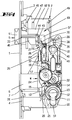
- the espagnolette lock shown has a lock housing 2 connected to a cuff 1.
- the cuff which projects over the lock housing 2 on both sides, covers an upper and a lower drive rod 3, 4 emerging from the lock housing 2 .
- a latch 5 is passed through the cuff 1, which is composed of a latch head 5 'and a latch tail 5' '. Furthermore, a bolt 6 is guided below the latch 5 in the lock housing 2. This passes through a cross-section-adapted opening 7 of the cuff 1.
- a lock base 8 and a lock cover 9 extend at right angles to the cuff 1. In their lower region of the lock housing 2, they hold a support plate 10 between them. This supports a toothed ring 12 which forms a radial gap 11 in its lower region. The latter is penetrated by a profile Lock cylinder 13, which is positively received by lock cylinder insertion openings in the lock base 8 and lock cover 9.
- the axis of rotation of the cylinder core and thus a closing element of the profile locking cylinder, indicated by dash-dotted lines is eccentric to the axis of rotation of the ring gear, below it.
- the aforementioned rack 17 is used to control the bolt 6, which is closed or closed depending on the rotation of the end wheel 16 via the rack 17.
- this is state of the art, so that it will not be discussed in more detail.
- actuating arm 20 which is mounted between cuff 1 and ring gear 12 about a journal 21.
- the journal 21 is seated in an arch slot 10 'of the carrier plate 10, so that the actuating arm 20, in addition to its pivoting movement, also carries out an upward displacement in the arch slot 10' can
- the actuating arm 20 is designed as a hook pawl pointing in the circumferential direction of the ring gear 12 and is loaded by a torsion spring 22 in the direction of engagement with a hook projection 23. in the the rest of the actuating arm 20 is part of a change lever arrangement W.
- an intermediate link 24 which is guided approximately parallel to the cuff 1, by attacking the shorter lever arm of the actuating arm 20 prevents it from entering the path of movement of the tooth 23 of the ring gear 12.
- the intermediate member 24 is part of a change lever arrangement W and is under the action of a compression spring 25 which shifts the intermediate member 24 into a stop-limited lower position.
- the upper end 24 'of the intermediate member 24 represents a plunger which interacts with an arm 26 of an angularly shaped deflection member 27.
- the deflection member 27 is mounted around a stationary stud 28.
- the aforementioned arm 26 connects with the other arm 29 of the deflection member 27 at an angle of approximately 90 ° and serves to retract the latch 5.
- the deflection member 27 is also part of the change lever arrangement W.
- a torsion spring 30 arranged on the standing pin 28 is supported on the one hand on the housing and on the other hand on the latch tail 5 ′′ and thus represents the latch spring.
- the end wheel 16 also acts in a manner not shown, but in a known manner, with a lower connecting rod connecting slide 31, which in turn carries the lower connecting rod 4.
- a driver projection 32 is arranged, which serves to control the intermediate member 24.
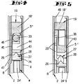
- the structure of the trap 5 is particularly apparent from Figure 6.
- the starting area of the trap tail 5 '' facing the trap head 5 ' is designed as an interchangeable mandrel 33 of circular cross-section.
- the mandrel 33 is in turn firmly connected to the trap head 5 ', for example by injection molding.
- the end of the mandrel 33 opposite the latch head 5 ' is inserted into the end region of the latch tail 5''and secured in its position by a grub screw 34.
- the grub screw 34 interacts with an end annular groove 35 of the mandrel 33.
- the end region of the trap tail 5 '' is designed as a molded part F and, in conjunction with the mandrel 33, forms a Z-shaped trap tail 5 ''.
- the mandrel 33 forms the one Z-leg, to which the Z-web 36 connects.
- the latter continues in the Z-leg 37 running parallel to the Z-leg (mandrel 33).
- This is provided with an extension 38 facing the lock cover 9, on which the nut arm 39 engages a nut 40 mounted below the latch tail.
- a spring-loaded slide 41 loads the nut 40 counterclockwise into a stop-limited position, see FIG. 2.
- the crossing arrangement between the angled leg 18 of the connecting rod connecting slide 19, which runs parallel to the cuff 1, and the latch tail 5 ′′ also emerges in particular from FIG. This is such that the nut 40 and its point of engagement (extension 38) on the latch tail 5 '' is on the other side of the cuff-parallel angle leg 18 than the latch head 5 '.
- the Z-shaped bend on the trap head side extends on the trap head side of the intersection area.
- the arm 29 of the angular deflection member 27 engages the Z-web 36.
- the Z-web 36 is provided on the side facing the lock base 8 with a recess 42 into which the arm 29 projects.
- arm 29 lies with its central portion on a step 42 ′ of recess 42 2. See Figure 2.
- the slightly angled end 29 'of the arm 29 extends at a short distance from the driving surface 42'', which merges into the step 42'.
- the molded part F On its side opposite the recess 42, the molded part F is surmounted by a guide rib 43, which in turn slides along the inner wall of the lock ceiling 9.
- An intermediate guide 44 is assigned to the mandrel 33. This is designed as a support bracket and extends in a fixed manner between the lock base 8 and lock cover 9. The intermediate guide 44 limits the occurrence of the latch 5 in that the Z-web 36 acts on this intermediate guide 44, see FIG. 2.
- the Z-shaped angled portion 36 of the latch tail 5 ′′ lies in the region between the guide section 45 and the cuff-parallel angle leg 18 of the connecting rod connecting slide 19.
- the cylinder core of the profile locking cylinder 13 must be turned counterclockwise.
- the ring gear 12 is rotated, which drives the end wheel 16 via the reduction gears. This displaces the connecting rod connecting slides 18, 31 in opposite directions.
- the bolt 6 is pre-locked via the rack 17. The closing is done by the opposite closing rotation.
- the espagnolette can be made spatially small in the area of the trap tail. Furthermore, there is a favorable closing method with a stable structure.
Landscapes
- Engineering & Computer Science (AREA)
- Mechanical Engineering (AREA)
- Lock And Its Accessories (AREA)
- Catching Or Destruction (AREA)
- Seats For Vehicles (AREA)
- Polysaccharides And Polysaccharide Derivatives (AREA)
- Saccharide Compounds (AREA)
- Orthopedics, Nursing, And Contraception (AREA)
Applications Claiming Priority (2)
| Application Number | Priority Date | Filing Date | Title |
|---|---|---|---|
| DE4242523A DE4242523C5 (de) | 1992-12-16 | 1992-12-16 | Treibstangenschloß |
| DE4242523 | 1992-12-16 |
Publications (2)
| Publication Number | Publication Date |
|---|---|
| EP0602323A1 true EP0602323A1 (fr) | 1994-06-22 |
| EP0602323B1 EP0602323B1 (fr) | 1996-11-27 |
Family
ID=6475475
Family Applications (1)
| Application Number | Title | Priority Date | Filing Date |
|---|---|---|---|
| EP93114122A Expired - Lifetime EP0602323B1 (fr) | 1992-12-16 | 1993-09-03 | Serrure avec bielle motrice |
Country Status (3)
| Country | Link |
|---|---|
| EP (1) | EP0602323B1 (fr) |
| AT (1) | ATE145701T1 (fr) |
| DE (2) | DE4242523C5 (fr) |
Cited By (2)
| Publication number | Priority date | Publication date | Assignee | Title |
|---|---|---|---|---|
| GB2294085A (en) * | 1994-10-11 | 1996-04-17 | Fullex Ltd | Shoot bolt fastening for windows or doors |
| AT14920U1 (de) * | 2015-02-19 | 2016-08-15 | Roto Frank Ag | Schloss |
Citations (3)
| Publication number | Priority date | Publication date | Assignee | Title |
|---|---|---|---|---|
| FR2488318A1 (fr) * | 1980-08-08 | 1982-02-12 | Chauvat Sofranq | Serrure a larder du type trois points |
| DE3144663A1 (de) * | 1980-11-13 | 1982-06-24 | Rohrbacher Schlosserwarenfabrik Wilh. Grundmann GmbH & Co KG, 3163 Rohrbach | Tuerverschluss |
| EP0454960A2 (fr) * | 1990-05-02 | 1991-11-06 | Carl Fuhr GmbH & Co. | Cremone |
Family Cites Families (1)
| Publication number | Priority date | Publication date | Assignee | Title |
|---|---|---|---|---|
| DE3830835C2 (de) * | 1988-09-10 | 1997-06-19 | Fuhr Carl Gmbh & Co | Drückerbetätigbares Schloß |
-
1992
- 1992-12-16 DE DE4242523A patent/DE4242523C5/de not_active Expired - Lifetime
-
1993
- 1993-09-03 DE DE59304611T patent/DE59304611D1/de not_active Expired - Lifetime
- 1993-09-03 AT AT93114122T patent/ATE145701T1/de active
- 1993-09-03 EP EP93114122A patent/EP0602323B1/fr not_active Expired - Lifetime
Patent Citations (3)
| Publication number | Priority date | Publication date | Assignee | Title |
|---|---|---|---|---|
| FR2488318A1 (fr) * | 1980-08-08 | 1982-02-12 | Chauvat Sofranq | Serrure a larder du type trois points |
| DE3144663A1 (de) * | 1980-11-13 | 1982-06-24 | Rohrbacher Schlosserwarenfabrik Wilh. Grundmann GmbH & Co KG, 3163 Rohrbach | Tuerverschluss |
| EP0454960A2 (fr) * | 1990-05-02 | 1991-11-06 | Carl Fuhr GmbH & Co. | Cremone |
Cited By (3)
| Publication number | Priority date | Publication date | Assignee | Title |
|---|---|---|---|---|
| GB2294085A (en) * | 1994-10-11 | 1996-04-17 | Fullex Ltd | Shoot bolt fastening for windows or doors |
| GB2294085B (en) * | 1994-10-11 | 1998-04-22 | Fullex Ltd | Shoot bolt fastening for windows or doors |
| AT14920U1 (de) * | 2015-02-19 | 2016-08-15 | Roto Frank Ag | Schloss |
Also Published As
| Publication number | Publication date |
|---|---|
| DE4242523C2 (de) | 2002-02-14 |
| DE4242523C5 (de) | 2005-08-25 |
| EP0602323B1 (fr) | 1996-11-27 |
| ATE145701T1 (de) | 1996-12-15 |
| DE4242523A1 (de) | 1994-06-23 |
| DE59304611D1 (de) | 1997-01-09 |
Similar Documents
| Publication | Publication Date | Title |
|---|---|---|
| DE8909801U1 (de) | Treibstangenschloß | |
| EP0634552B1 (fr) | Clef avec pêne rotatif, spécialement comme serrure supplémentaire à barres coulissantes | |
| EP0455944B1 (fr) | Serrure de barre coulissante manoeuvrable d'un barillet | |
| EP0454966B1 (fr) | Serrure avec bielle motrice actionnée par cylindre de fermeture | |
| EP0677634A1 (fr) | Serrure mortaisée, en particulier pour portes de maison, notamment crémone | |
| EP0670403B1 (fr) | Serrure pour porte, notamment serrure encastrée | |
| EP0385213A2 (fr) | Crémone | |
| EP1020597A1 (fr) | Serrure à crémone avec une serrure principal et une serrure complémentaire | |
| EP0581338B1 (fr) | Serrure de barre coulissante manoeuvrable d'un barillet | |
| EP0454960B1 (fr) | Cremone | |
| EP0602323B1 (fr) | Serrure avec bielle motrice | |
| DE4014045C2 (de) | Einsteckschloß, insbesondere Treibstangenschloß | |
| DE19815671B4 (de) | Treibstangenverschluß | |
| EP0454958A1 (fr) | Serrure, notamment serrure avec bielle motrice | |
| EP0828048A2 (fr) | Serrure, notamment serrure encastrée | |
| EP0972900B1 (fr) | Crémone-serrure | |
| DE3901957C2 (de) | Treibstangenverschluß, insbesondere für Balkontüren | |
| EP0496076B1 (fr) | Crémone-serrure | |
| EP0391063B1 (fr) | Crémone | |
| DE19756116A1 (de) | Treibstangenverschluß | |
| DE9007786U1 (de) | Schließzylinderbetätigbares Treibstangenschloß | |
| DE4302920A1 (de) | Schloß, insbesondere Einsteckschloß |
Legal Events
| Date | Code | Title | Description |
|---|---|---|---|
| PUAI | Public reference made under article 153(3) epc to a published international application that has entered the european phase |
Free format text: ORIGINAL CODE: 0009012 |
|
| 17P | Request for examination filed |
Effective date: 19940321 |
|
| AK | Designated contracting states |
Kind code of ref document: A1 Designated state(s): AT DE FR GB IT |
|
| 17Q | First examination report despatched |
Effective date: 19950714 |
|
| GRAH | Despatch of communication of intention to grant a patent |
Free format text: ORIGINAL CODE: EPIDOS IGRA |
|
| GRAH | Despatch of communication of intention to grant a patent |
Free format text: ORIGINAL CODE: EPIDOS IGRA |
|
| GRAA | (expected) grant |
Free format text: ORIGINAL CODE: 0009210 |
|
| AK | Designated contracting states |
Kind code of ref document: B1 Designated state(s): AT DE FR GB IT |
|
| REF | Corresponds to: |
Ref document number: 145701 Country of ref document: AT Date of ref document: 19961215 Kind code of ref document: T |
|
| GBT | Gb: translation of ep patent filed (gb section 77(6)(a)/1977) |
Effective date: 19961127 |
|
| ET | Fr: translation filed | ||
| REF | Corresponds to: |
Ref document number: 59304611 Country of ref document: DE Date of ref document: 19970109 |
|
| ITF | It: translation for a ep patent filed | ||
| PLBE | No opposition filed within time limit |
Free format text: ORIGINAL CODE: 0009261 |
|
| 26N | No opposition filed | ||
| REG | Reference to a national code |
Ref country code: GB Ref legal event code: IF02 |
|
| PGFP | Annual fee paid to national office [announced via postgrant information from national office to epo] |
Ref country code: GB Payment date: 20120912 Year of fee payment: 20 |
|
| PGFP | Annual fee paid to national office [announced via postgrant information from national office to epo] |
Ref country code: IT Payment date: 20120926 Year of fee payment: 20 Ref country code: DE Payment date: 20120907 Year of fee payment: 20 Ref country code: FR Payment date: 20120921 Year of fee payment: 20 |
|
| PGFP | Annual fee paid to national office [announced via postgrant information from national office to epo] |
Ref country code: AT Payment date: 20120910 Year of fee payment: 20 |
|
| REG | Reference to a national code |
Ref country code: DE Ref legal event code: R071 Ref document number: 59304611 Country of ref document: DE |
|
| REG | Reference to a national code |
Ref country code: GB Ref legal event code: PE20 Expiry date: 20130902 |
|
| REG | Reference to a national code |
Ref country code: AT Ref legal event code: MK07 Ref document number: 145701 Country of ref document: AT Kind code of ref document: T Effective date: 20130903 |
|
| PG25 | Lapsed in a contracting state [announced via postgrant information from national office to epo] |
Ref country code: DE Free format text: LAPSE BECAUSE OF EXPIRATION OF PROTECTION Effective date: 20130904 |
|
| PG25 | Lapsed in a contracting state [announced via postgrant information from national office to epo] |
Ref country code: GB Free format text: LAPSE BECAUSE OF EXPIRATION OF PROTECTION Effective date: 20130902 |