EP0602348A1 - Méthode de commande de la température de l'air de suralimentation et dispositif pour sa mise en oeuvre - Google Patents
Méthode de commande de la température de l'air de suralimentation et dispositif pour sa mise en oeuvre Download PDFInfo
- Publication number
- EP0602348A1 EP0602348A1 EP93116945A EP93116945A EP0602348A1 EP 0602348 A1 EP0602348 A1 EP 0602348A1 EP 93116945 A EP93116945 A EP 93116945A EP 93116945 A EP93116945 A EP 93116945A EP 0602348 A1 EP0602348 A1 EP 0602348A1
- Authority
- EP
- European Patent Office
- Prior art keywords
- pressure
- charge air
- line
- temperature
- pressure sensor
- Prior art date
- Legal status (The legal status is an assumption and is not a legal conclusion. Google has not performed a legal analysis and makes no representation as to the accuracy of the status listed.)
- Withdrawn
Links
Images
Classifications
-
- F—MECHANICAL ENGINEERING; LIGHTING; HEATING; WEAPONS; BLASTING
- F02—COMBUSTION ENGINES; HOT-GAS OR COMBUSTION-PRODUCT ENGINE PLANTS
- F02B—INTERNAL-COMBUSTION PISTON ENGINES; COMBUSTION ENGINES IN GENERAL
- F02B29/00—Engines characterised by provision for charging or scavenging not provided for in groups F02B25/00, F02B27/00 or F02B33/00 - F02B39/00; Details thereof
- F02B29/04—Cooling of air intake supply
- F02B29/0493—Controlling the air charge temperature
-
- F—MECHANICAL ENGINEERING; LIGHTING; HEATING; WEAPONS; BLASTING
- F02—COMBUSTION ENGINES; HOT-GAS OR COMBUSTION-PRODUCT ENGINE PLANTS
- F02B—INTERNAL-COMBUSTION PISTON ENGINES; COMBUSTION ENGINES IN GENERAL
- F02B29/00—Engines characterised by provision for charging or scavenging not provided for in groups F02B25/00, F02B27/00 or F02B33/00 - F02B39/00; Details thereof
- F02B29/04—Cooling of air intake supply
- F02B29/0406—Layout of the intake air cooling or coolant circuit
- F02B29/0418—Layout of the intake air cooling or coolant circuit the intake air cooler having a bypass or multiple flow paths within the heat exchanger to vary the effective heat transfer surface
-
- F—MECHANICAL ENGINEERING; LIGHTING; HEATING; WEAPONS; BLASTING
- F02—COMBUSTION ENGINES; HOT-GAS OR COMBUSTION-PRODUCT ENGINE PLANTS
- F02M—SUPPLYING COMBUSTION ENGINES IN GENERAL WITH COMBUSTIBLE MIXTURES OR CONSTITUENTS THEREOF
- F02M31/00—Apparatus for thermally treating combustion-air, fuel, or fuel-air mixture
- F02M31/02—Apparatus for thermally treating combustion-air, fuel, or fuel-air mixture for heating
- F02M31/04—Apparatus for thermally treating combustion-air, fuel, or fuel-air mixture for heating combustion-air or fuel-air mixture
- F02M31/042—Combustion air
-
- Y—GENERAL TAGGING OF NEW TECHNOLOGICAL DEVELOPMENTS; GENERAL TAGGING OF CROSS-SECTIONAL TECHNOLOGIES SPANNING OVER SEVERAL SECTIONS OF THE IPC; TECHNICAL SUBJECTS COVERED BY FORMER USPC CROSS-REFERENCE ART COLLECTIONS [XRACs] AND DIGESTS
- Y02—TECHNOLOGIES OR APPLICATIONS FOR MITIGATION OR ADAPTATION AGAINST CLIMATE CHANGE
- Y02T—CLIMATE CHANGE MITIGATION TECHNOLOGIES RELATED TO TRANSPORTATION
- Y02T10/00—Road transport of goods or passengers
- Y02T10/10—Internal combustion engine [ICE] based vehicles
- Y02T10/12—Improving ICE efficiencies
Definitions
- the invention relates to a method according to the preamble of claim 1.
- an internal combustion engine with control of the charge air temperature in which the charge air is fed to the air manifold after a compressor of the exhaust gas turbocharger controlled by an actuator either with the interposition of a preheater or a charge air cooler.
- the path of the charge air is controlled by a temperature-dependent actuator, which is arranged at the entrance of the air manifold.
- the temperature-dependent control of the actuator is accomplished by a bimetal spring. If the charge air coming from the compressor is too cold, the bimetallic spring sets a flap of the actuator so that the outlet of the charge air cooler is blocked, whereby the charge air is guided through a preheater.
- the bimetallic spring switches the valve of the actuator in such a way that the output of the preheater is blocked, so that the charge air is guided over the charge air cooler. Since the flap is controlled by the bimetal spring acting as a thermostat, the reversal reacts with a high time delay, since the bimetal spring, like other commercially available thermostats, has a relatively high thermal inertia and therefore only respond with a time delay.
- the object of the invention is to develop a method which allows the desired charge air temperature to be reached as quickly as possible, without the charge air cooling being delayed in the higher load range.
- the fact that the actuator is controlled by a pressure sensor results in a much faster response of the reversing mechanism.
- the pressure sensor follows the pressure increase or pressure drop of the charge air almost without delay, i. H. the temperature change physically associated with the pressure change due to polytropic compression.
- the pressure sensor can be functionally coupled to a thermostat that reacts to the ambient temperature in such a way that the temperature fluctuations in the environment, which are small over time, are also taken into account.
- the thermostat which has a secondary influence on the pressure sensor, only reacts to the temperature in the intake line, i.e. actually to the prevailing ambient temperature, which changes very slowly over time, in any case much more slowly than the charge air temperature behind the compressor in unsteady engine operation.
- a device for performing the method according to claims 1 and 2 can be found in claim 3.
- the pressure sensor is connected to the pressure line via a line, the line between the compressor and the actuator branches off and the pressure sensor primarily triggers the actuation of the actuator due to the pressure increase after the compressor. Secondarily, the outside temperature acts on the pressure sensor via the temperature-controlled preload force of the spring.
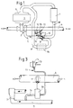
- the control valve 6 has a flap 10, which from a Actuator 11 is actuated.
- the actuator 11 in turn consists of a thermostat 12 and a pressure sensor 13, wherein the thermostat 12 detects the temperature of the intake air in the intake line 4.
- the pressure sensor 13 communicates via line 14 with the pressure line 5 and, after a predetermined pressure level has been exceeded, switches the flap 10 out of the position shown in such a way that the air initially led via the bypass line 8 or an air preheater 8a built into the bypass line 8 follows the charge air cooler 7 must pass when a predetermined pressure level is reached via a charge air line 15.
- the pressure sensor 13 is influenced by the temperature of the intake air from the thermostat 12 in such a way that the pressure level specified for actuating the flap 10 is set higher at a low temperature of the air in the intake line 4 than at a higher temperature of the air in the intake line 4
- the case is, that is, that the pressure sensor 13 responds only at a higher pressure level at a lower temperature of the intake air than is the case at a higher temperature of the intake air.
- the method according to the invention is based on the knowledge that the temperature difference between the air in the suction line 4 and the pressure line 5 can be described by their pressure difference in the form of a polytropic change in state.
- the particular advantage of the method according to the invention can be seen in the fact that the pressure sensor 13 of the actuator 11 responds much faster than a thermostat could do.
- the thermostat 12 only has the task of varying the response pressure of the pressure sensor 13 as a function of the ambient temperature.
- the inertia of the thermostat 12, which is still present, is insignificant, since the temperature of the air in the intake manifold 4 changes very slowly over time as a function of the ambient temperature.
- the flap 10 can be actuated by the pressure sensor 13 almost without delay.
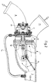
- FIG. 2 An embodiment of the actuator 11 is shown in Figure 2.
- the flap 10 connects the pressure line 5 either to the bypass line 8, or after switching from the position shown with a charge air line 15, which leads to the charge air cooler 7 ( Figure 1).
- the flap 10 is actuated primarily by the pressure sensor 13.
- a pressure chamber 16 of the pressure sensor 13 communicates with the pressure line 5 via the line 14.
- the reversal can be controlled by a membrane 17 and a linkage 18 the flap 10 from the position shown.
- the thermostat 12 reacting to the ambient temperature can be omitted.
- the temperature of the charge air is then only regulated via the pressure sensor 13 as a function of a polytropic change of state.
- a variation of the actuator 11 is shown schematically in Figure 3.
- the response pressure of the pressure sensor 13 is varied with the aid of a modulating valve 20 such that the pressure in the pressure chamber 16 of the pressure sensor 13 is raised when the temperature of the intake air in the intake line 4 drops, or vice versa.
- the modulating valve 20 is controlled by the thermostat 12 which is built into the intake line 4.
- the pressure in the pressure chamber 16 of the pressure sensor 13 can therefore be varied on the basis of the pressure in the pressure line 12 as a function of the temperature in the suction line 4 by means of the modulating valve 20.
- the thermostat 12 with the modulating valve can also be dispensed with here if the requirements for the constancy of the charge air temperature are reduced and emphasis is placed on simple design.
Landscapes
- Engineering & Computer Science (AREA)
- Chemical & Material Sciences (AREA)
- Combustion & Propulsion (AREA)
- Mechanical Engineering (AREA)
- General Engineering & Computer Science (AREA)
- Physics & Mathematics (AREA)
- Thermal Sciences (AREA)
- Supercharger (AREA)
Applications Claiming Priority (2)
| Application Number | Priority Date | Filing Date | Title |
|---|---|---|---|
| DE4242010 | 1992-12-12 | ||
| DE4242010A DE4242010A1 (de) | 1992-12-12 | 1992-12-12 | Verfahren zur Regelung der Ladelufttemperatur, sowie Vorrichtung zu dessen Durchführung |
Publications (1)
| Publication Number | Publication Date |
|---|---|
| EP0602348A1 true EP0602348A1 (fr) | 1994-06-22 |
Family
ID=6475135
Family Applications (1)
| Application Number | Title | Priority Date | Filing Date |
|---|---|---|---|
| EP93116945A Withdrawn EP0602348A1 (fr) | 1992-12-12 | 1993-10-20 | Méthode de commande de la température de l'air de suralimentation et dispositif pour sa mise en oeuvre |
Country Status (3)
| Country | Link |
|---|---|
| EP (1) | EP0602348A1 (fr) |
| JP (1) | JPH06212980A (fr) |
| DE (1) | DE4242010A1 (fr) |
Cited By (8)
| Publication number | Priority date | Publication date | Assignee | Title |
|---|---|---|---|---|
| EP0708231A1 (fr) * | 1994-10-21 | 1996-04-24 | Valeo Thermique Moteur | Dispositif de commande du refroidissement de l'air de suralimentation d'un moteur thermique |
| US5546975A (en) * | 1993-10-05 | 1996-08-20 | Renault Vehicules Industriels | Control device for a fluid passing through a bypass and system equipped with such a device to regulate the supercharging air of an internal combustion engine |
| WO1998025012A1 (fr) * | 1996-12-02 | 1998-06-11 | Caterpillar Inc. | Derivation chauffee de refroidisseur secondaire air-air a soupape de commutation a detection de charge |
| US5947064A (en) * | 1995-10-10 | 1999-09-07 | Man B&W Diesel A/S | Multi-engine plant with a common freshwater cooling system |
| FR2859504A1 (fr) * | 2003-09-04 | 2005-03-11 | Renault Sa | Circuit pour l'alimentation d'un collecteur d'admission d'air d'un moteur thermique de vehicule automobile |
| CN101432509B (zh) * | 2006-04-26 | 2012-06-06 | 法雷奥电机控制系统公司 | 用于热机的进气装置的阀 |
| FR2970305A1 (fr) * | 2011-01-11 | 2012-07-13 | Peugeot Citroen Automobiles Sa | Module d'alimentation en air sous pression d'un moteur a combustion interne |
| CN109798179A (zh) * | 2019-01-19 | 2019-05-24 | 潍柴重机股份有限公司 | 一种增压空气放气装置及放气方法 |
Families Citing this family (4)
| Publication number | Priority date | Publication date | Assignee | Title |
|---|---|---|---|---|
| DE4302339C2 (de) * | 1993-01-28 | 2001-06-07 | Bosch Gmbh Robert | Verfahren und Vorrichtung zur Begrenzung der höchstzulässigen Kraftstoffmenge |
| KR19980060474A (ko) * | 1996-12-31 | 1998-10-07 | 박병재 | 자동차의 과급 장치 |
| EP1923552B1 (fr) * | 2006-11-15 | 2013-07-24 | MANN+HUMMEL GmbH | Unité de commande de la température |
| FR2925610B1 (fr) * | 2007-12-19 | 2014-03-28 | Valeo Sys Controle Moteur Sas | Vanne pour systeme d'admission d'air de moteur thermique |
Citations (10)
| Publication number | Priority date | Publication date | Assignee | Title |
|---|---|---|---|---|
| GB1153655A (en) * | 1966-07-23 | 1969-05-29 | Maschf Augsburg Nuernberg Ag | Improvements in or relating to Internal Combustion Engines |
| US3712282A (en) * | 1971-01-22 | 1973-01-23 | Teledyne Ind | Temperature control system for supercharged internal combustion engine |
| GB2001128A (en) * | 1977-07-12 | 1979-01-24 | Alsacienne Constr Meca | A supercharged diesel engine |
| GB2055963A (en) * | 1979-08-06 | 1981-03-11 | Alsacienne Constr Meca | Supercharging Internal Combustion Engines |
| FR2495689A1 (en) * | 1980-12-08 | 1982-06-11 | Hyperbar Develop Suralimentati | Coolant circuit for diesel engine - has heat exchanger in air intake for recuperator air and fuel circuit |
| EP0080984A2 (fr) * | 1981-12-01 | 1983-06-08 | Ab Volvo | Système d'admission d'air pour moteur suralimenté avec refroidissement d'air de suralimentation |
| EP0080983A2 (fr) * | 1981-12-01 | 1983-06-08 | Ab Volvo | Système d'admission d'air pour moteur suralimenté avec refroidissement d'air de suralimentation |
| JPS61112730A (ja) * | 1984-11-05 | 1986-05-30 | Toyo Radiator Kk | 過給器用給気冷却装置 |
| JPS61190114A (ja) * | 1985-02-18 | 1986-08-23 | Mazda Motor Corp | インタ−ク−ラ付タ−ボ過給機のサ−ジング防止装置 |
| JPS63195324A (ja) * | 1987-02-07 | 1988-08-12 | Mazda Motor Corp | 過給機付エンジンの吸気冷却装置 |
Family Cites Families (4)
| Publication number | Priority date | Publication date | Assignee | Title |
|---|---|---|---|---|
| DE3214205A1 (de) * | 1982-04-17 | 1983-10-20 | Klöckner-Humboldt-Deutz AG, 5000 Köln | Brennkraftmaschine mit zumindest einem abgasturbolader |
| US4483150A (en) * | 1983-02-28 | 1984-11-20 | Societe Pour Le Developpement De La Suralimentation Hyperbar | Supercharged internal combustion engines provided with a cooling system |
| DE3627686A1 (de) * | 1986-08-14 | 1987-11-12 | Daimler Benz Ag | Brennkraftmaschine mit einem abgasturbolader |
| SU1726810A1 (ru) * | 1990-05-29 | 1992-04-15 | Челябинское Высшее Военное Автомобильное Инженерное Училище Им.Главного Маршала Бронетанковых Войск П.А.Ротмистрова | Устройство дл регулировани температуры наддувочного воздуха двигател внутреннего сгорани |
-
1992
- 1992-12-12 DE DE4242010A patent/DE4242010A1/de not_active Withdrawn
-
1993
- 1993-10-20 EP EP93116945A patent/EP0602348A1/fr not_active Withdrawn
- 1993-12-13 JP JP5311936A patent/JPH06212980A/ja active Pending
Patent Citations (10)
| Publication number | Priority date | Publication date | Assignee | Title |
|---|---|---|---|---|
| GB1153655A (en) * | 1966-07-23 | 1969-05-29 | Maschf Augsburg Nuernberg Ag | Improvements in or relating to Internal Combustion Engines |
| US3712282A (en) * | 1971-01-22 | 1973-01-23 | Teledyne Ind | Temperature control system for supercharged internal combustion engine |
| GB2001128A (en) * | 1977-07-12 | 1979-01-24 | Alsacienne Constr Meca | A supercharged diesel engine |
| GB2055963A (en) * | 1979-08-06 | 1981-03-11 | Alsacienne Constr Meca | Supercharging Internal Combustion Engines |
| FR2495689A1 (en) * | 1980-12-08 | 1982-06-11 | Hyperbar Develop Suralimentati | Coolant circuit for diesel engine - has heat exchanger in air intake for recuperator air and fuel circuit |
| EP0080984A2 (fr) * | 1981-12-01 | 1983-06-08 | Ab Volvo | Système d'admission d'air pour moteur suralimenté avec refroidissement d'air de suralimentation |
| EP0080983A2 (fr) * | 1981-12-01 | 1983-06-08 | Ab Volvo | Système d'admission d'air pour moteur suralimenté avec refroidissement d'air de suralimentation |
| JPS61112730A (ja) * | 1984-11-05 | 1986-05-30 | Toyo Radiator Kk | 過給器用給気冷却装置 |
| JPS61190114A (ja) * | 1985-02-18 | 1986-08-23 | Mazda Motor Corp | インタ−ク−ラ付タ−ボ過給機のサ−ジング防止装置 |
| JPS63195324A (ja) * | 1987-02-07 | 1988-08-12 | Mazda Motor Corp | 過給機付エンジンの吸気冷却装置 |
Non-Patent Citations (3)
| Title |
|---|
| PATENT ABSTRACTS OF JAPAN vol. 10, no. 299 (M - 524)<2355> 11 October 1986 (1986-10-11) * |
| PATENT ABSTRACTS OF JAPAN vol. 11, no. 14 (M - 553)<2461> 14 January 1987 (1987-01-14) * |
| PATENT ABSTRACTS OF JAPAN vol. 12, no. 475 (M - 774)<3322> 13 December 1988 (1988-12-13) * |
Cited By (11)
| Publication number | Priority date | Publication date | Assignee | Title |
|---|---|---|---|---|
| US5546975A (en) * | 1993-10-05 | 1996-08-20 | Renault Vehicules Industriels | Control device for a fluid passing through a bypass and system equipped with such a device to regulate the supercharging air of an internal combustion engine |
| EP0708231A1 (fr) * | 1994-10-21 | 1996-04-24 | Valeo Thermique Moteur | Dispositif de commande du refroidissement de l'air de suralimentation d'un moteur thermique |
| FR2726039A1 (fr) * | 1994-10-21 | 1996-04-26 | Valeo Thermique Moteur Sa | Dispositif de commande du refroidissement de l'air de suralimentation d'un moteur thermique |
| US5649516A (en) * | 1994-10-21 | 1997-07-22 | Valeo Thermique Moteur | Device for controlling the temperature of supercharging air for a heat engine |
| US5947064A (en) * | 1995-10-10 | 1999-09-07 | Man B&W Diesel A/S | Multi-engine plant with a common freshwater cooling system |
| WO1998025012A1 (fr) * | 1996-12-02 | 1998-06-11 | Caterpillar Inc. | Derivation chauffee de refroidisseur secondaire air-air a soupape de commutation a detection de charge |
| FR2859504A1 (fr) * | 2003-09-04 | 2005-03-11 | Renault Sa | Circuit pour l'alimentation d'un collecteur d'admission d'air d'un moteur thermique de vehicule automobile |
| EP1512853A3 (fr) * | 2003-09-04 | 2010-05-19 | Renault s.a.s. | Circuit pour l'alimentation d'un collecteur d'admission d'air d'un moteur thermique de véhicule automobile |
| CN101432509B (zh) * | 2006-04-26 | 2012-06-06 | 法雷奥电机控制系统公司 | 用于热机的进气装置的阀 |
| FR2970305A1 (fr) * | 2011-01-11 | 2012-07-13 | Peugeot Citroen Automobiles Sa | Module d'alimentation en air sous pression d'un moteur a combustion interne |
| CN109798179A (zh) * | 2019-01-19 | 2019-05-24 | 潍柴重机股份有限公司 | 一种增压空气放气装置及放气方法 |
Also Published As
| Publication number | Publication date |
|---|---|
| DE4242010A1 (de) | 1994-06-16 |
| JPH06212980A (ja) | 1994-08-02 |
Similar Documents
| Publication | Publication Date | Title |
|---|---|---|
| DE3039435C2 (de) | Vorrichtung zur Regelung der Leerlauf-Drehzahl von Brennkraftmaschinen | |
| DE3205111C2 (fr) | ||
| DE19502150C1 (de) | System zur Regelung der Aufladung einer Brennkraftmaschine | |
| DE3020131C2 (fr) | ||
| EP0602348A1 (fr) | Méthode de commande de la température de l'air de suralimentation et dispositif pour sa mise en oeuvre | |
| DE10256966A1 (de) | Bypass-Ventilsystem bei einem durch einen Turbolader aufgeladenen Motor | |
| DE3000781C2 (de) | Einrichtung zur Steuerung des Betätigungsdruckes für den Stellantrieb eines Nebenstromventils in einer Umgehungsleitung der Turbine eines Abgasturboladers | |
| DE2003924C3 (de) | Steuervorrichtung fur eine Kraft stoffeinspntzeinnchtung | |
| DE3138058C2 (fr) | ||
| DE102014210207A1 (de) | Steuervorrichtung und Steuerverfahren für Innenverbrennungsmotor | |
| EP0077996B1 (fr) | Procédé et dispositif de réglage de la vitesse de ralenti pour moteur à combustion | |
| DE3238189A1 (de) | Leerlauf-regelsystem fuer eine brennkraftmaschine | |
| EP0761955A2 (fr) | Méthode de commande d'un moeteur à combustion interne suralimenté | |
| DE2902731A1 (de) | Drehzahlregler fuer einspritzbrennkraftmaschinen, insbesondere fliehkraftdrehzahlregler einer einspritzpumpe fuer fahrzeugdieselmotoren | |
| DE3306484A1 (de) | Abgas-steuervorrichtung fuer brennkraftmaschinen mit turbolader und katalytischem konverter zur abgasentgiftung | |
| EP0035691B1 (fr) | Dispositif de réglage de la pression de suralimentation pour des moteurs à combustion interne | |
| EP0434788B1 (fr) | Systeme pour la commande d'un moteur a combustion interne | |
| EP1830049B1 (fr) | Procédé et appareil de commande destinés au réglage d'une section de passage de turbine d'un turbocompresseur | |
| DE3216032C2 (de) | Anordnung zum Regeln der Kühlwassertemperatur eines wassergekühlten Motors | |
| US2796733A (en) | Turbine engine fuel control using a final electrical signal for proportionally moving a single throttle valve | |
| GB1237680A (en) | Flow metering apparatus, particularly for combustion engine fuel control | |
| DE3014842C2 (de) | Brennkraftmaschine | |
| DE3928833C2 (fr) | ||
| EP0728922B1 (fr) | Régulation de débit de masse d'air avec constante d'intégration adaptée pour moteur à combustion interne turbocompressée | |
| EP0399016B1 (fr) | Procede et dispositif pour adapter la courbe caracteristique d'un regulateur de ralenti |
Legal Events
| Date | Code | Title | Description |
|---|---|---|---|
| PUAI | Public reference made under article 153(3) epc to a published international application that has entered the european phase |
Free format text: ORIGINAL CODE: 0009012 |
|
| AK | Designated contracting states |
Kind code of ref document: A1 Designated state(s): AT DE FR IT SE |
|
| STAA | Information on the status of an ep patent application or granted ep patent |
Free format text: STATUS: THE APPLICATION IS DEEMED TO BE WITHDRAWN |
|
| 18D | Application deemed to be withdrawn |
Effective date: 19941223 |