EP0080983A2 - Système d'admission d'air pour moteur suralimenté avec refroidissement d'air de suralimentation - Google Patents
Système d'admission d'air pour moteur suralimenté avec refroidissement d'air de suralimentation Download PDFInfo
- Publication number
- EP0080983A2 EP0080983A2 EP82850224A EP82850224A EP0080983A2 EP 0080983 A2 EP0080983 A2 EP 0080983A2 EP 82850224 A EP82850224 A EP 82850224A EP 82850224 A EP82850224 A EP 82850224A EP 0080983 A2 EP0080983 A2 EP 0080983A2
- Authority
- EP
- European Patent Office
- Prior art keywords
- temperature
- charge air
- air
- pressure
- charge
- Prior art date
- Legal status (The legal status is an assumption and is not a legal conclusion. Google has not performed a legal analysis and makes no representation as to the accuracy of the status listed.)
- Withdrawn
Links
Images


Classifications
-
- F—MECHANICAL ENGINEERING; LIGHTING; HEATING; WEAPONS; BLASTING
- F02—COMBUSTION ENGINES; HOT-GAS OR COMBUSTION-PRODUCT ENGINE PLANTS
- F02B—INTERNAL-COMBUSTION PISTON ENGINES; COMBUSTION ENGINES IN GENERAL
- F02B29/00—Engines characterised by provision for charging or scavenging not provided for in groups F02B25/00, F02B27/00 or F02B33/00 - F02B39/00; Details thereof
- F02B29/04—Cooling of air intake supply
- F02B29/0406—Layout of the intake air cooling or coolant circuit
- F02B29/0418—Layout of the intake air cooling or coolant circuit the intake air cooler having a bypass or multiple flow paths within the heat exchanger to vary the effective heat transfer surface
-
- F—MECHANICAL ENGINEERING; LIGHTING; HEATING; WEAPONS; BLASTING
- F02—COMBUSTION ENGINES; HOT-GAS OR COMBUSTION-PRODUCT ENGINE PLANTS
- F02B—INTERNAL-COMBUSTION PISTON ENGINES; COMBUSTION ENGINES IN GENERAL
- F02B29/00—Engines characterised by provision for charging or scavenging not provided for in groups F02B25/00, F02B27/00 or F02B33/00 - F02B39/00; Details thereof
- F02B29/04—Cooling of air intake supply
- F02B29/0493—Controlling the air charge temperature
-
- F—MECHANICAL ENGINEERING; LIGHTING; HEATING; WEAPONS; BLASTING
- F02—COMBUSTION ENGINES; HOT-GAS OR COMBUSTION-PRODUCT ENGINE PLANTS
- F02B—INTERNAL-COMBUSTION PISTON ENGINES; COMBUSTION ENGINES IN GENERAL
- F02B3/00—Engines characterised by air compression and subsequent fuel addition
- F02B3/06—Engines characterised by air compression and subsequent fuel addition with compression ignition
-
- Y—GENERAL TAGGING OF NEW TECHNOLOGICAL DEVELOPMENTS; GENERAL TAGGING OF CROSS-SECTIONAL TECHNOLOGIES SPANNING OVER SEVERAL SECTIONS OF THE IPC; TECHNICAL SUBJECTS COVERED BY FORMER USPC CROSS-REFERENCE ART COLLECTIONS [XRACs] AND DIGESTS
- Y02—TECHNOLOGIES OR APPLICATIONS FOR MITIGATION OR ADAPTATION AGAINST CLIMATE CHANGE
- Y02T—CLIMATE CHANGE MITIGATION TECHNOLOGIES RELATED TO TRANSPORTATION
- Y02T10/00—Road transport of goods or passengers
- Y02T10/10—Internal combustion engine [ICE] based vehicles
- Y02T10/12—Improving ICE efficiencies
Definitions
- the present invention relates to a system for supplying combustion air to the cylinders in a combustion engine for vehicles, comprising a compressor for elevating the pressure of the air supplied to the air intake of the cylinders, a charge air cooler for cooling the charge air from the compressor, and a valve which permits the supply of charge air from the compressor directly to the engine air intake, by-passing the charge air cooler.
- Turbo-charged combustion engines with charge air cooling have been known for quite some time.
- the primary reason for using charge air coolers is to reduce the thermal and mechanical stresses at high power output from the engine as well as to reduce emissions, particularly smoke and NO x .
- the lower temperature results directly in reduced smoke and NO x and indirectly presents the possibility of delaying the combustion process (so that-the NO x content can be further reduced) without the thermal stresses at high power output exceeding permissible levels.
- the most common method of cooling the charge air is to use a water/air or an air/air heat exchanger.
- the former type is normally used with the engine coolant as the cooling medium.
- the disadvantage of this is that the cooling capacity is limited and that the charge air is cooled at most to a temperature which lies in the vicinity of the coolant temperature.
- at low load - for a short time at least - it is possible to heat the charge air. It is of course possible to reduce the temperature in the charge air cooler by using a separate water coolant system with a lower temperature, as is done in marine engines with access to water cooling, but in vehicle engines this leads to major complications.
- the ambient air is normally used directly as the cooling agent and the temperature of the charge air can be lowered to a temperature which is only 20 - 30°C higher than the temperature of the ambient air at full load and very close to this temperature at low load.
- the advantages of this good cooling at full load are however reduced by the risk of poor combustion with high percentages of non-combusted fuel in the exhaust at low load, especially at low ambient air temperature.
- Systems which regulate the charge air temperature to an essentially constant temperature regardless of the engine load and speed and regardless of the temperature of the outside air.
- the known systems can be divided into a type with a thermostat-controlled shunt valve and a type without a shunt valve but with a heat-carrying medium with constant temperature such as a water/air cooler for example.
- These systems can to be sure prevent at low ambient temperatures excessive cooling of the charge air at low load, but the first-mentioned system has an excessively slow reaction time for rapid changes in load due to the fact that the reaction time is determined and limited by the heat capacity of the thermostat.
- the latter system has a limited cooling capacity when using the engine coolant, or becomes very complicated when using an extra water coolant system.
- the purpose of the present invention is to achieve a system of the type described by way of introduction, which makes it possible to reduce particle, gas and noise emissions from engines by regulating the temperature of the charge air after a predetermined period of time to predetermined values coupled to the engine load and speed independently of the temperature of the ambient air.
- valve being a two-way valve controlled by the charge pressure and the temperature of the ambient air, said valve at a given ambient air temperature and at a charge pressure less than a predetermined pressure conducting essentially all the charge air past the charge air cooler, and at said ambient air temperature and at a charge pressure exceeding a predetermined pressure conducting essentially all of the charge air through the charge air cooler, said valve cooperating with a temperature-controlled means which, at temperatures less than said given ambient air temperature, raises said predetermined pressure and, at temperatures exceeding said given temperature, lowers said predetermined pressure.
- the system according to the invention provides high temperature in the engine cylinders at low load when the charge pressure is low and all the charge air is shunted past the cooler. At full load there is no reduction of the charge air cooling.
- the system does not limit the rapidity of the adjustment to load changes, by virtue of the fact that the valve is controlled in the first place by the charge pressure.
- the temperature-controlled means only needs to respond to the temperature variations in the ambient air, which means that even a long response time is sufficient.
- Fig. 1 shows schematically a diesel engine 1 with an intake manifold 2 and an exhaust manifold 3. The latter is connected to an exhaust pipe with a muffler 4 via a turbine 5 which drives a compressor 6.
- a pipe 7 connects, via a charge air cooler 8, the outlet of the compressor to the intake manifold 2.
- the valve 10, shown in the lower branching piece between the pipe 7 and the pipe 9, comprises a gate 21 hinged about a shaft 20 and which in the intermediate position shown in the figure supplies the engine cylinders with a mixture of cooled and uncooled charge air and which at its both end positions blocks one of the air passages.
- the position of the gate thus determines in what proportion cooled and uncooled air will be mixed in order to supply the engine with-air at a given temperature.
- the gate 21 is coupled mechanically to a pneumatic setting means 22 in the form of a piston-cylinder device the piston 23 of which is joined to the gate 21 via a piston rod 19 articulated at both ends.
- the cylinder chamber 24a on the piston rod side is completely open to the shunt pipe 9, and the piston 23 is thus loaded on its underside only by a force dependent on the charge pressure.
- the cylinder chamber 24b on the opposite side contains a compression spring 25 and communicates via a bore 26, a pipe 27 and a restriction 28 with the shunt pipe 9. Furthermore the chamber 24b communicates via a pipe 29 with an overflow valve 30 having a valve body 31 which is biased towards the closed position by a. bimetallic spring 32. Charge air diverted via the overflow valve 30 is led back to the suction side of the compressor through a pipe (not shwon). The piston is thus loaded on the top side by a force which, in addition to the spring force, is dependent on the charge pressure and the temperature of the ambient air, since this temperature determines the opening pressure of the valve 30.
- the temperature of the charge air in the shunt pipe 9 is a function of the temperature prior to the compressor 6 and of the pressure rise in the compressor.
- the temperature of the charge air is determined by the charge pressure, and by determining at what pressure the gate is to begin letting in charge air via the cooler 8 through the pipe 7 it is possible to determine the highest suitable temperature of the air supplied to the engine cylinders.
- the desired charge air temperature corresponds to a higher charge pressure.
- the bimetallic spring 32 in the valve 30 is selected and arranged so that the opening pressure of the valve 30 increases with decreasing ambient temperature, which means that it will require a higher charge pressure before the gate will open and let out cooled charge air via the cooler 8. The lower temperature of the ambient air is thus compensated for by higher pressure of the charge air, so that the resulting temperature at which the gate 21 begins to open to let out cooled charge air is kept practically constant independently of the ambient air temperature.
- Each gate position between the end positions is regulated in a corresponding manner.
- the temperature compensation is achieved in the example described by virtue of the fact that the bending of a bimetallic spring varies nearly linearly with the temperature.
- the closing force will instead vary nearly linearly with the temperature which, because of the design of the valve, will result in the opening pressure increasing linearly with decreasing ambient temperature. Since the temperature at compression in the compressor increases essentially linearly with the pressure over small pressure increases, a lower temperature of the air before the compressor can be compensated for by a nearly proportional pressure rise.
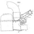
- Fig. 3 shows a shunt valve 40 according to the invention in a practical embodiment.
- the gate 41 is joined here to a curved arm 42 which is rotatably mounted on a shaft 43.
- the gate is biased towards the position shown with dash-dot lines by a torsion spring 44 and is coupled mechanically to a pneumatic operating means in the form of a piston-cylinder device, the piston 46 of which is joined to the gate via a flexible metal band 47.
- the restricted communication between the shunt pipe 9 and the cylinder chamber 48 on the top of the piston is formed here by a gap 49 between the piston and the cylinder wall, which is maintained by using a piston without a seal.
- the cylinder chamber 48 also communicates with an overflow valve (not shown) corresponding to the valve 30 in the example in Fig. 2.
- the functioning of the shunt valve 40 with the associated overflow valve is analogous to that described in connection with the example in Fig. 2.
- the charge air temperature is thus regulated by indidrect measurement of the charge air temperature by measuring the charge air pressure and measuring the temperature of the ambient air, the charge air pressure being used as the control medium to achieve the desired reaction speed to changes in the charge air temperature caused by changes in the engine load.
- the desired rection speed means here that it can be set at very rapid (as rapid as the charge pressure or the temperature rise, which propagates at the speed of sound) and up to an arbitrarily long reaction time by using restrictions and air volume.
- the temperature compensation need only be sufficiently rapid to follow changes in the temperature of the outside air.
Landscapes
- Engineering & Computer Science (AREA)
- Physics & Mathematics (AREA)
- Thermal Sciences (AREA)
- Chemical & Material Sciences (AREA)
- Combustion & Propulsion (AREA)
- Mechanical Engineering (AREA)
- General Engineering & Computer Science (AREA)
- Supercharger (AREA)
- Temperature-Responsive Valves (AREA)
Applications Claiming Priority (2)
| Application Number | Priority Date | Filing Date | Title |
|---|---|---|---|
| SE8107167 | 1981-12-01 | ||
| SE8107167A SE460303B (sv) | 1981-12-01 | 1981-12-01 | Anordning foer tillfoersel av foerbraenningsluft till cylindrarna i en foerbraenningsmotor |
Publications (2)
| Publication Number | Publication Date |
|---|---|
| EP0080983A2 true EP0080983A2 (fr) | 1983-06-08 |
| EP0080983A3 EP0080983A3 (fr) | 1984-05-30 |
Family
ID=20345171
Family Applications (1)
| Application Number | Title | Priority Date | Filing Date |
|---|---|---|---|
| EP82850224A Withdrawn EP0080983A3 (fr) | 1981-12-01 | 1982-11-05 | Système d'admission d'air pour moteur suralimenté avec refroidissement d'air de suralimentation |
Country Status (3)
| Country | Link |
|---|---|
| EP (1) | EP0080983A3 (fr) |
| JP (1) | JPS58104322A (fr) |
| SE (1) | SE460303B (fr) |
Cited By (7)
| Publication number | Priority date | Publication date | Assignee | Title |
|---|---|---|---|---|
| EP0602348A1 (fr) * | 1992-12-12 | 1994-06-22 | MAN Nutzfahrzeuge Aktiengesellschaft | Méthode de commande de la température de l'air de suralimentation et dispositif pour sa mise en oeuvre |
| EP0646702A1 (fr) * | 1993-10-05 | 1995-04-05 | RENAULT VEHICULES INDUSTRIELS Société Anonyme dite: | Procédé et dispositif de commande d'un fluide traversant un boîtier de dérivation et système équipé d'un tel dispositif pour réguler l'air de suralimentation d'un moteur à combustion interne |
| EP0708231A1 (fr) * | 1994-10-21 | 1996-04-24 | Valeo Thermique Moteur | Dispositif de commande du refroidissement de l'air de suralimentation d'un moteur thermique |
| EP1455078A1 (fr) * | 2003-03-06 | 2004-09-08 | Ford Global Technologies, Inc., A subsidiary of Ford Motor Company | Moteur à combustion interne ayant un turbocompresseur et un système de recyclage des gaz d'échappement |
| EP3114335A4 (fr) * | 2014-03-07 | 2017-11-22 | Kristani, Filip | Moteur à combustion interne deux temps à compression à refroidissement par étage préalable |
| CN108757240A (zh) * | 2018-06-05 | 2018-11-06 | 潍柴动力股份有限公司 | 一种柴油发动机进气系统及热管理方法、装置 |
| CN109838303A (zh) * | 2017-11-29 | 2019-06-04 | 福特全球技术公司 | 加压进气系统 |
Families Citing this family (1)
| Publication number | Priority date | Publication date | Assignee | Title |
|---|---|---|---|---|
| JPS6137427U (ja) * | 1984-08-11 | 1986-03-08 | 三菱重工業株式会社 | 内燃機関の給気供給装置 |
Family Cites Families (6)
| Publication number | Priority date | Publication date | Assignee | Title |
|---|---|---|---|---|
| CH413494A (de) * | 1964-01-31 | 1966-05-15 | Sulzer Ag | Aufgeladene Dieselbrennkraftmaschine sowie Verfahren zu deren Betrieb |
| US3712282A (en) * | 1971-01-22 | 1973-01-23 | Teledyne Ind | Temperature control system for supercharged internal combustion engine |
| FR2461101A1 (fr) * | 1979-08-06 | 1981-01-30 | Alsacienne Constr Meca | Dispositif de regulation de l'air de suralimentation des moteurs diesel |
| FR2495689A1 (en) * | 1980-12-08 | 1982-06-11 | Hyperbar Develop Suralimentati | Coolant circuit for diesel engine - has heat exchanger in air intake for recuperator air and fuel circuit |
| JPS6018589U (ja) * | 1983-07-18 | 1985-02-07 | 日本電気株式会社 | 宅内機器の筐体構造 |
| JPS6154930A (ja) * | 1984-08-28 | 1986-03-19 | 大倉工業株式会社 | 熱収縮包装用フイルム及びそれを用いた包装体 |
-
1981
- 1981-12-01 SE SE8107167A patent/SE460303B/sv unknown
-
1982
- 1982-11-05 EP EP82850224A patent/EP0080983A3/fr not_active Withdrawn
- 1982-12-01 JP JP57211208A patent/JPS58104322A/ja active Pending
Cited By (12)
| Publication number | Priority date | Publication date | Assignee | Title |
|---|---|---|---|---|
| EP0602348A1 (fr) * | 1992-12-12 | 1994-06-22 | MAN Nutzfahrzeuge Aktiengesellschaft | Méthode de commande de la température de l'air de suralimentation et dispositif pour sa mise en oeuvre |
| EP0646702A1 (fr) * | 1993-10-05 | 1995-04-05 | RENAULT VEHICULES INDUSTRIELS Société Anonyme dite: | Procédé et dispositif de commande d'un fluide traversant un boîtier de dérivation et système équipé d'un tel dispositif pour réguler l'air de suralimentation d'un moteur à combustion interne |
| FR2710953A1 (fr) * | 1993-10-05 | 1995-04-14 | Renault Vehicules Ind | Procédé et dispositif de commande d'un fluide traversant un boîtier de dérivation et système équipé d'un tel dispositif pour réguler l'air de suralimentation d'un moteur à combustion interne. |
| US5546975A (en) * | 1993-10-05 | 1996-08-20 | Renault Vehicules Industriels | Control device for a fluid passing through a bypass and system equipped with such a device to regulate the supercharging air of an internal combustion engine |
| EP0708231A1 (fr) * | 1994-10-21 | 1996-04-24 | Valeo Thermique Moteur | Dispositif de commande du refroidissement de l'air de suralimentation d'un moteur thermique |
| FR2726039A1 (fr) * | 1994-10-21 | 1996-04-26 | Valeo Thermique Moteur Sa | Dispositif de commande du refroidissement de l'air de suralimentation d'un moteur thermique |
| US5649516A (en) * | 1994-10-21 | 1997-07-22 | Valeo Thermique Moteur | Device for controlling the temperature of supercharging air for a heat engine |
| EP1455078A1 (fr) * | 2003-03-06 | 2004-09-08 | Ford Global Technologies, Inc., A subsidiary of Ford Motor Company | Moteur à combustion interne ayant un turbocompresseur et un système de recyclage des gaz d'échappement |
| EP3114335A4 (fr) * | 2014-03-07 | 2017-11-22 | Kristani, Filip | Moteur à combustion interne deux temps à compression à refroidissement par étage préalable |
| CN109838303A (zh) * | 2017-11-29 | 2019-06-04 | 福特全球技术公司 | 加压进气系统 |
| CN109838303B (zh) * | 2017-11-29 | 2025-05-16 | 福特全球技术公司 | 加压进气系统 |
| CN108757240A (zh) * | 2018-06-05 | 2018-11-06 | 潍柴动力股份有限公司 | 一种柴油发动机进气系统及热管理方法、装置 |
Also Published As
| Publication number | Publication date |
|---|---|
| SE460303B (sv) | 1989-09-25 |
| JPS58104322A (ja) | 1983-06-21 |
| EP0080983A3 (fr) | 1984-05-30 |
| SE8107167L (sv) | 1983-06-02 |
Similar Documents
| Publication | Publication Date | Title |
|---|---|---|
| US3355877A (en) | Supercharged diesel engine power plants | |
| US6138650A (en) | Method of controlling fuel injectors for improved exhaust gas recirculation | |
| EP0080984B1 (fr) | Système d'admission d'air pour moteur suralimenté avec refroidissement d'air de suralimentation | |
| US4207848A (en) | Charging air heat-exchanger installation | |
| US5740786A (en) | Internal combustion engine with an exhaust gas recirculation system | |
| US7100584B1 (en) | Method and apparatus for controlling an internal combustion engine | |
| US4697551A (en) | Quick-response control system for low-flow engine coolant systems | |
| US9353876B2 (en) | Boost pressure control system for turbocharged internal combustion engines | |
| MXPA01003078A (es) | Sistema de recirculacion de gas de escape para un motor turbocargado. | |
| US7305976B1 (en) | Engine heater and method | |
| EP0080983A2 (fr) | Système d'admission d'air pour moteur suralimenté avec refroidissement d'air de suralimentation | |
| US4483150A (en) | Supercharged internal combustion engines provided with a cooling system | |
| US3483854A (en) | Compressed gas expander cooling apparatus | |
| EP1211400B1 (fr) | Système de régulation de la température de l'air d'admission | |
| CN101341327A (zh) | 内燃机废气再循环的装置和方法 | |
| JPH05209529A (ja) | 2段階式の過給空気冷却機構を備えた内燃機関 | |
| US4515136A (en) | Supercharged diesel engine air inflow control system | |
| US4489702A (en) | Supercharged diesel engine air flow control system | |
| JPS595781B2 (ja) | 過給機付エンジンの燃料制御装置 | |
| JPS58165524A (ja) | 内燃機関用過給圧調節装置 | |
| US4513730A (en) | Supercharged diesel engine air inflow control system | |
| GB2335483A (en) | Method and apparatus for cooling an engine using exhaust gas | |
| JPS60147533A (ja) | インタ−ク−ラ付エンジンの給気冷却装置 | |
| KR19980053771U (ko) | 터보 과급 엔진의 급기 냉각장치 | |
| KR100475799B1 (ko) | 디젤엔진의 흡입공기 과급장치 및 그 제어방법 |
Legal Events
| Date | Code | Title | Description |
|---|---|---|---|
| PUAI | Public reference made under article 153(3) epc to a published international application that has entered the european phase |
Free format text: ORIGINAL CODE: 0009012 |
|
| 17P | Request for examination filed |
Effective date: 19821109 |
|
| AK | Designated contracting states |
Designated state(s): CH DE FR GB IT LI NL |
|
| PUAL | Search report despatched |
Free format text: ORIGINAL CODE: 0009013 |
|
| AK | Designated contracting states |
Designated state(s): CH DE FR GB IT LI NL |
|
| STAA | Information on the status of an ep patent application or granted ep patent |
Free format text: STATUS: THE APPLICATION IS DEEMED TO BE WITHDRAWN |
|
| 18D | Application deemed to be withdrawn |
Effective date: 19860116 |
|
| RIN1 | Information on inventor provided before grant (corrected) |
Inventor name: HAKANSSON, NILS OLOF |