EP0602408A1 - Broyeur - Google Patents
Broyeur Download PDFInfo
- Publication number
- EP0602408A1 EP0602408A1 EP93118708A EP93118708A EP0602408A1 EP 0602408 A1 EP0602408 A1 EP 0602408A1 EP 93118708 A EP93118708 A EP 93118708A EP 93118708 A EP93118708 A EP 93118708A EP 0602408 A1 EP0602408 A1 EP 0602408A1
- Authority
- EP
- European Patent Office
- Prior art keywords
- cutting
- counter
- tool
- tooth
- rotation
- Prior art date
- Legal status (The legal status is an assumption and is not a legal conclusion. Google has not performed a legal analysis and makes no representation as to the accuracy of the status listed.)
- Granted
Links
- 239000000463 material Substances 0.000 claims abstract description 24
- 230000036346 tooth eruption Effects 0.000 claims abstract description 12
- 230000004323 axial length Effects 0.000 claims description 3
- 230000033001 locomotion Effects 0.000 description 4
- 230000005540 biological transmission Effects 0.000 description 2
- 238000011161 development Methods 0.000 description 1
- 230000018109 developmental process Effects 0.000 description 1
- 239000010921 garden waste Substances 0.000 description 1
- 238000003780 insertion Methods 0.000 description 1
- 230000037431 insertion Effects 0.000 description 1
Images
Classifications
-
- B—PERFORMING OPERATIONS; TRANSPORTING
- B02—CRUSHING, PULVERISING, OR DISINTEGRATING; PREPARATORY TREATMENT OF GRAIN FOR MILLING
- B02C—CRUSHING, PULVERISING, OR DISINTEGRATING IN GENERAL; MILLING GRAIN
- B02C18/00—Disintegrating by knives or other cutting or tearing members which chop material into fragments
- B02C18/06—Disintegrating by knives or other cutting or tearing members which chop material into fragments with rotating knives
- B02C18/16—Details
- B02C18/18—Knives; Mountings thereof
- B02C18/186—Axially elongated knives
-
- B—PERFORMING OPERATIONS; TRANSPORTING
- B02—CRUSHING, PULVERISING, OR DISINTEGRATING; PREPARATORY TREATMENT OF GRAIN FOR MILLING
- B02C—CRUSHING, PULVERISING, OR DISINTEGRATING IN GENERAL; MILLING GRAIN
- B02C18/00—Disintegrating by knives or other cutting or tearing members which chop material into fragments
- B02C18/06—Disintegrating by knives or other cutting or tearing members which chop material into fragments with rotating knives
- B02C18/16—Details
- B02C18/18—Knives; Mountings thereof
- B02C2018/188—Stationary counter-knives; Mountings thereof
Definitions
- the invention relates to a chopper or chopper of the type defined in the preamble of claim 1.
- the cutting tool designed as a cutting roller is arranged at the lower end of a loading shaft provided with an insertion funnel, the cross section of the cutting roller roughly corresponding to the lower starting cross section of the loading shaft.
- the stationary counter knife is designed as a bar inclined downward from the circumference of the cutting roller, so that there is a cutting edge which is angular in cross section.
- the bar is adjustable attached to a crossbar.
- the reamer interacting with the cutting roller which clears the tooth gaps in which the material of the chopped material passing through the counter knife is taken away and is free as a back and forth
- the front surface of the slider is bevelled so that there is a tooth-shaped engagement tip.
- the slide is arranged here on the lower flank of the loading shaft opposite the counter knife and is driven by the shaft of the cutting roller in a reciprocating motion via a cam.
- the chopper or chopper according to the invention with the characterizing features of claim 1 has the advantage of being structurally much simpler, which makes it considerably more robust and can be produced much more cheaply.
- Counter knife and reamer are realized by a single component, the so-called counter tool, which takes over the function of both.
- the component is rotationally symmetrical and can be easily manufactured. It is driven in rotation so that the relatively less robust and failure-prone device for converting the movement of a rotary movement into an axial reciprocating slide movement, as is present in the known chopper, is eliminated.
- the workpiece or chopped material is cut safely and the cutting tool is reliably cleared from the tooth gaps. When regrinding the cutting tool, it is not necessary to readjust the counter tool.
- Helical teeth on the cutting tool are possible to achieve the necessary performance and reduce the bearing forces.
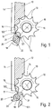
- a roller-shaped cutting tool 10 is arranged in the lower initial cross section of a loading shaft, of which only the left side wall is shown, which is a contact wall 11 for the material to be shredded Workpiece or chopped material 12 forms.
- the chopped material 12 is pressed against this contact wall 11 when the cutting tool penetrates it.
- the rotating cutting tool 10 has cutting teeth 13 and tooth gaps 14, which are distributed uniformly over its circumference and alternately in succession, and extend over the entire axial length of the cutting tool 10.
- the cutting tool 10 with its axis of rotation 15 running in the depth of the drawing sheet is arranged relative to the contact wall 11 in such a way that the contact wall 11 extends approximately tangentially to the cutting tool 10, namely up to the tangent point denoted by 16 or running into the depth of the drawing plane Tangent line. From there, the contact wall 11 extends in an arcuate manner to a line which runs into the depth of the drawing plane and is identified by 17 and extends parallel to the axis of rotation 15.
- the circle radius of this arcuate curvature is slightly larger than the radius of the turning circle of the cutting tooth tips and has the same center of curvature.
- a counter-tool 20 is provided to hold the chopped material against the cutting tool 10, to shred it and to clear out the material to be cut off in the tooth gaps 17 after passage through the cutting tool 10, which counter-tool 20 extends parallel to and about the axis of rotation 15 of the cutting tool 10 radially offset axis of rotation 19 is rotatably supported and driven to rotate.
- the direction of rotation of the counter tool 20 is opposite to the direction of rotation of the cutting tool 10, and the speed of rotation of the counter tool 20 is in a fixed ratio to the speed of rotation of the cutting tool 10. The ratio depends on the design of the counter tool 20 and the cutting tool 10 and is closer below explained.
- the counter tool 20 has two projecting arm-like counter cutting edges 21, 22 which are arranged diametrically to one another on the counter tool 20 and extend over the entire axial length of the cutting tool 10 or the counter tool 20 and are designed such that they are successively in successive tooth gaps 14 of the cutting tool 10 screw in, the counter-cutting tips in each case on the cutting tooth tip of successive cutting teeth 13 screwing into the tooth gap 14 preceding the respective cutting tooth 13 in the direction of rotation and sliding therein approximately along the tooth gap contour.
- the front boundary surface of the counter cutting edges 21, 22 in the direction of rotation each has an approximately arcuate and the rear boundary surface of the counter cutting edge 21, 22 in the direction of rotation each has an approximately flat, tangential contour.
- the counter-cutting tips are tooth-shaped when viewed in the direction of rotation, the tooth shape being similar to that of the cutting teeth 13.
- the speed of rotation of the counter tool 20 with the two counter cutting edges 21, 22 is z / 2 times greater than that of the cutting tool 10, where z is the number of cutting teeth 13.
- the cutting tool 10 has ten cutting teeth 13, so that the rotational speed of the counter tool 20 is five times as large as that of the cutting tool 10.
- the drive for the counter tool 20 is expediently via a transmission gear with a transmission ratio of 5: 1 Drive for the cutting tool 10 derived.
- the counter tool 20 can also be used with only one shear bar or three or four shear bars. Its rotational speed is then z / n times larger than the rotational speed of the cutting tool 10, where n is the number of counter cutting edges.
- the chopped material 12 thrown into the loading chute is gripped and drawn in by the front flanks of the cutting teeth 13.
- the chopped material 12 is pressed against the contact wall 11, which accordingly also functions as a feed wall.
- the chopped material 12 is held in reliable contact with the system wall 11. This hold-down effect prevents impact noise and makes it easier to cut the chopped material 12 in the area of line 17 in connection with the counter tool 20.
- the tooth gaps 14 in which the cut material 121, 122 is picked up when passing the line 17, is cleared out and kept free by means of the counter cutting edges 21 and 22 of the counter tool 20, which also acts as a reamer. As can be seen in the comparison of FIGS.
- the counter cutting edge 21 plunges into the tooth gap 14 preceding in the direction of rotation of the cutting tool 10 and pushes the gap therein , material 121 separated from the chopped material 12 from the tooth gap 14 (FIG. 2).
- the tooth gap 14 is cleared and can absorb material again when immersed in the chopped material 12.
- the shearbar 22, together with the subsequent cutting tooth 13 cuts off the next piece of material 122 and then clears it out by immersing it in the leading tooth gap 14 in the same manner as described above.
- the counter tool 20 is cleared of chopped material by the cutting tool 10.
Landscapes
- Engineering & Computer Science (AREA)
- Food Science & Technology (AREA)
- Crushing And Pulverization Processes (AREA)
- Milling Processes (AREA)
Applications Claiming Priority (2)
| Application Number | Priority Date | Filing Date | Title |
|---|---|---|---|
| DE4242640A DE4242640A1 (de) | 1992-12-17 | 1992-12-17 | Häcksler |
| DE4242640 | 1992-12-17 |
Publications (2)
| Publication Number | Publication Date |
|---|---|
| EP0602408A1 true EP0602408A1 (fr) | 1994-06-22 |
| EP0602408B1 EP0602408B1 (fr) | 1997-04-02 |
Family
ID=6475549
Family Applications (1)
| Application Number | Title | Priority Date | Filing Date |
|---|---|---|---|
| EP93118708A Expired - Lifetime EP0602408B1 (fr) | 1992-12-17 | 1993-11-22 | Broyeur |
Country Status (3)
| Country | Link |
|---|---|
| US (1) | US5373998A (fr) |
| EP (1) | EP0602408B1 (fr) |
| DE (2) | DE4242640A1 (fr) |
Families Citing this family (4)
| Publication number | Priority date | Publication date | Assignee | Title |
|---|---|---|---|---|
| DE4344738A1 (de) * | 1993-12-28 | 1995-06-29 | Bosch Gmbh Robert | Häcksler |
| DE19518378C1 (de) * | 1995-05-23 | 1996-11-14 | Elektra Beckum Ag | Gartenhäcksler |
| CN115228570B (zh) * | 2022-07-21 | 2024-11-26 | 南京绿上农业开发有限公司 | 一种具有防止物料缠绕功能的撕碎机 |
| DE102022121330A1 (de) * | 2022-08-23 | 2024-02-29 | Claas Saulgau Gmbh | Häckselwerk einer landwirtschaftlichen Erntemaschine |
Citations (2)
| Publication number | Priority date | Publication date | Assignee | Title |
|---|---|---|---|---|
| GB2059804A (en) * | 1979-10-16 | 1981-04-29 | Sant Andrea Novara Officine | Comminuting machine |
| EP0469380A1 (fr) * | 1990-07-28 | 1992-02-05 | Lescha Maschinenfabrik GmbH & Co. KG | Hacheuse |
Family Cites Families (5)
| Publication number | Priority date | Publication date | Assignee | Title |
|---|---|---|---|---|
| US98757A (en) * | 1870-01-11 | Improvement in cider-mills | ||
| US1032132A (en) * | 1911-10-20 | 1912-07-09 | Charles Gormley | Fertilizer-distributer. |
| US4410144A (en) * | 1981-02-26 | 1983-10-18 | General Steel Industries, Inc. | Synchronously coordinated counterrotated crusher roll teeth system |
| US4401279A (en) * | 1981-08-27 | 1983-08-30 | General Steel Industries, Inc. | Synchronously counter-rotating intermeshing differential speed crusher roll assembly |
| JP3188909B2 (ja) * | 1991-07-17 | 2001-07-16 | 松爾 中込 | 2軸破砕機 |
-
1992
- 1992-12-17 DE DE4242640A patent/DE4242640A1/de not_active Withdrawn
-
1993
- 1993-11-22 EP EP93118708A patent/EP0602408B1/fr not_active Expired - Lifetime
- 1993-11-22 DE DE59306028T patent/DE59306028D1/de not_active Expired - Fee Related
- 1993-12-15 US US08/167,770 patent/US5373998A/en not_active Expired - Fee Related
Patent Citations (3)
| Publication number | Priority date | Publication date | Assignee | Title |
|---|---|---|---|---|
| GB2059804A (en) * | 1979-10-16 | 1981-04-29 | Sant Andrea Novara Officine | Comminuting machine |
| EP0469380A1 (fr) * | 1990-07-28 | 1992-02-05 | Lescha Maschinenfabrik GmbH & Co. KG | Hacheuse |
| DE4024060C2 (fr) * | 1990-07-28 | 1992-08-20 | Lescha Maschinenfabrik Gmbh & Co Kg, 8900 Augsburg, De |
Also Published As
| Publication number | Publication date |
|---|---|
| EP0602408B1 (fr) | 1997-04-02 |
| DE59306028D1 (de) | 1997-05-07 |
| DE4242640A1 (de) | 1994-06-23 |
| US5373998A (en) | 1994-12-20 |
Similar Documents
| Publication | Publication Date | Title |
|---|---|---|
| DE2649305C3 (de) | Lochscheibe für einen Fleischwolf | |
| DE4024060C2 (fr) | ||
| EP1687091B1 (fr) | Dispositif de concassage des contenants vides | |
| DE3305063A1 (de) | Abfall-zerkleinerungsvorrichtung | |
| DE102019108306A1 (de) | Schneidmühle zum schneidenden Zerkleinern von Proben | |
| DE2701897A1 (de) | Vorrichtung zum zerkleinern von abfaellen unterschiedlicher art, insbesondere von industrieabfaellen und sperrmuell | |
| EP2070666A1 (fr) | Dispositif de coupe de faisceau | |
| CH659405A5 (de) | Zerkleinerungsvorrichtung fuer abfall. | |
| DE3221431A1 (de) | Vorrichtung zum zerkleinern von kunststoffteilen, insbesondere angussstuecken | |
| EP0387868B1 (fr) | Dispositif de broyage pour déchets de bois | |
| WO1998028079A1 (fr) | Hache-viande | |
| DE3874408T2 (de) | Zerkleinerungsapparat. | |
| DE2243467A1 (de) | Vorrichtung zum oeffnen von briefumschlaegen und dgl | |
| EP0602408B1 (fr) | Broyeur | |
| DE4444977C2 (de) | Zerkleinerungswerk | |
| DE4427700C2 (de) | Vorrichtung zum Häckseln von Gartenabfällen | |
| DE2618254A1 (de) | Messertrommel, insbesondere fuer hackmaschinen zur zerkleinerung von hoelzern und abfaellen | |
| DE2049124C3 (de) | Maschine zum Zerkleinern von sperrigem Gut | |
| DE10117154A1 (de) | Häckseleinrichtung | |
| EP2564930A1 (fr) | Hache | |
| EP0847805A1 (fr) | Outil de coupe pour transporteur rotatif à vis | |
| EP0089571B1 (fr) | Désintégrateur du bois | |
| DE3434303C2 (de) | Vorrichtung zum Zerkleinern von Abfall | |
| EP0505701A1 (fr) | Broyeur de déchets de jardin avec enceinte contenant des couteaux plats à entraîner en rotation | |
| DE8810996U1 (de) | Vorrichtung zum Zerkleinern von Ästen, Zweigen u.dgl. |
Legal Events
| Date | Code | Title | Description |
|---|---|---|---|
| PUAI | Public reference made under article 153(3) epc to a published international application that has entered the european phase |
Free format text: ORIGINAL CODE: 0009012 |
|
| AK | Designated contracting states |
Kind code of ref document: A1 Designated state(s): CH DE FR GB IT LI |
|
| 17P | Request for examination filed |
Effective date: 19941222 |
|
| GRAG | Despatch of communication of intention to grant |
Free format text: ORIGINAL CODE: EPIDOS AGRA |
|
| GRAH | Despatch of communication of intention to grant a patent |
Free format text: ORIGINAL CODE: EPIDOS IGRA |
|
| 17Q | First examination report despatched |
Effective date: 19960912 |
|
| GRAH | Despatch of communication of intention to grant a patent |
Free format text: ORIGINAL CODE: EPIDOS IGRA |
|
| GRAA | (expected) grant |
Free format text: ORIGINAL CODE: 0009210 |
|
| AK | Designated contracting states |
Kind code of ref document: B1 Designated state(s): CH DE FR GB IT LI |
|
| REG | Reference to a national code |
Ref country code: CH Ref legal event code: NV Representative=s name: SCINTILLA AG, DIREKTION Ref country code: CH Ref legal event code: EP |
|
| ET | Fr: translation filed | ||
| REF | Corresponds to: |
Ref document number: 59306028 Country of ref document: DE Date of ref document: 19970507 |
|
| GBT | Gb: translation of ep patent filed (gb section 77(6)(a)/1977) |
Effective date: 19970605 |
|
| PLBE | No opposition filed within time limit |
Free format text: ORIGINAL CODE: 0009261 |
|
| STAA | Information on the status of an ep patent application or granted ep patent |
Free format text: STATUS: NO OPPOSITION FILED WITHIN TIME LIMIT |
|
| 26N | No opposition filed | ||
| PGFP | Annual fee paid to national office [announced via postgrant information from national office to epo] |
Ref country code: CH Payment date: 19991125 Year of fee payment: 7 |
|
| PG25 | Lapsed in a contracting state [announced via postgrant information from national office to epo] |
Ref country code: LI Free format text: LAPSE BECAUSE OF NON-PAYMENT OF DUE FEES Effective date: 20001130 Ref country code: CH Free format text: LAPSE BECAUSE OF NON-PAYMENT OF DUE FEES Effective date: 20001130 |
|
| REG | Reference to a national code |
Ref country code: CH Ref legal event code: PL |
|
| REG | Reference to a national code |
Ref country code: GB Ref legal event code: IF02 |
|
| PG25 | Lapsed in a contracting state [announced via postgrant information from national office to epo] |
Ref country code: IT Free format text: LAPSE BECAUSE OF NON-PAYMENT OF DUE FEES;WARNING: LAPSES OF ITALIAN PATENTS WITH EFFECTIVE DATE BEFORE 2007 MAY HAVE OCCURRED AT ANY TIME BEFORE 2007. THE CORRECT EFFECTIVE DATE MAY BE DIFFERENT FROM THE ONE RECORDED. Effective date: 20051122 |
|
| PGFP | Annual fee paid to national office [announced via postgrant information from national office to epo] |
Ref country code: FR Payment date: 20071120 Year of fee payment: 15 |
|
| PGFP | Annual fee paid to national office [announced via postgrant information from national office to epo] |
Ref country code: DE Payment date: 20090126 Year of fee payment: 16 |
|
| PGFP | Annual fee paid to national office [announced via postgrant information from national office to epo] |
Ref country code: GB Payment date: 20081121 Year of fee payment: 16 |
|
| REG | Reference to a national code |
Ref country code: FR Ref legal event code: ST Effective date: 20090731 |
|
| GBPC | Gb: european patent ceased through non-payment of renewal fee |
Effective date: 20091122 |
|
| PG25 | Lapsed in a contracting state [announced via postgrant information from national office to epo] |
Ref country code: DE Free format text: LAPSE BECAUSE OF NON-PAYMENT OF DUE FEES Effective date: 20100601 |
|
| PG25 | Lapsed in a contracting state [announced via postgrant information from national office to epo] |
Ref country code: GB Free format text: LAPSE BECAUSE OF NON-PAYMENT OF DUE FEES Effective date: 20091122 |
|
| PG25 | Lapsed in a contracting state [announced via postgrant information from national office to epo] |
Ref country code: FR Free format text: LAPSE BECAUSE OF NON-PAYMENT OF DUE FEES Effective date: 20081130 |