EP0602431A1 - Dispositif de racle d'essuyage - Google Patents
Dispositif de racle d'essuyage Download PDFInfo
- Publication number
- EP0602431A1 EP0602431A1 EP93119115A EP93119115A EP0602431A1 EP 0602431 A1 EP0602431 A1 EP 0602431A1 EP 93119115 A EP93119115 A EP 93119115A EP 93119115 A EP93119115 A EP 93119115A EP 0602431 A1 EP0602431 A1 EP 0602431A1
- Authority
- EP
- European Patent Office
- Prior art keywords
- doctor blade
- squeegee
- forme cylinder
- doctor
- strip
- Prior art date
- Legal status (The legal status is an assumption and is not a legal conclusion. Google has not performed a legal analysis and makes no representation as to the accuracy of the status listed.)
- Granted
Links
- 238000007639 printing Methods 0.000 claims abstract description 45
- 238000004804 winding Methods 0.000 claims abstract description 27
- 230000004323 axial length Effects 0.000 claims abstract description 4
- 230000002950 deficient Effects 0.000 claims description 4
- 239000002184 metal Substances 0.000 claims description 4
- 230000002441 reversible effect Effects 0.000 claims 1
- 239000002699 waste material Substances 0.000 abstract description 6
- 230000006378 damage Effects 0.000 description 5
- 239000000463 material Substances 0.000 description 3
- 230000009471 action Effects 0.000 description 2
- 241001149900 Fusconaia subrotunda Species 0.000 description 1
- 230000008859 change Effects 0.000 description 1
- 238000011109 contamination Methods 0.000 description 1
- 239000000428 dust Substances 0.000 description 1
- 230000006870 function Effects 0.000 description 1
- 238000007646 gravure printing Methods 0.000 description 1
- 238000003780 insertion Methods 0.000 description 1
- 230000037431 insertion Effects 0.000 description 1
- 238000000034 method Methods 0.000 description 1
- 238000013021 overheating Methods 0.000 description 1
- 239000002245 particle Substances 0.000 description 1
- 238000003825 pressing Methods 0.000 description 1
- 230000008569 process Effects 0.000 description 1
- 230000009467 reduction Effects 0.000 description 1
- 230000001105 regulatory effect Effects 0.000 description 1
- 239000007787 solid Substances 0.000 description 1
Images

Classifications
-
- B—PERFORMING OPERATIONS; TRANSPORTING
- B41—PRINTING; LINING MACHINES; TYPEWRITERS; STAMPS
- B41F—PRINTING MACHINES OR PRESSES
- B41F9/00—Rotary intaglio printing presses
- B41F9/06—Details
- B41F9/08—Wiping mechanisms
- B41F9/10—Doctors, scrapers, or like devices
- B41F9/109—Doctors, scrapers, or like devices exchanging doctor blades
Definitions
- the invention relates to a doctor blade arrangement for a rotogravure printing machine of the type reproduced in the preamble of claim 1.
- the printing ink which is to be transferred to the material to be printed, is applied to the forme cylinders of rotogravure printing machines in such a way that the forme cylinder rotating at high speed with a region of its jacket surface which extends over its entire length into a printing ink Immersed in the bath, which is contained in an ink pan, the depressions formed in the surface of the forme cylinder filling with printing ink. Since excess ink adheres to the surface of the forme cylinder after it emerges from the printing ink bath, even on non-recessed surface areas, it is essential to arrange a so-called squeegee on the printing cylinder. with the help of this excess printing ink can be stripped off before the relevant area of the forme cylinder surface enters the printing zone and comes into contact with the material web to be printed there.
- doctor blades are usually designed in the manner of a relatively rigid metal ruler, the length of which is somewhat greater than the axial length of the associated forme cylinder.
- a squeegee is rigidly clamped in an equally long solid squeegee bar, with the aid of which it is positioned next to the forme cylinder in such a way that it can be pressed against the outer surface of the forme cylinder with the aid of a hydraulic or pneumatic device along a generatrix of the forme cylinder running parallel to the axis of rotation.
- doctor blade arrangements have a number of disadvantages.
- the durability of such a doctor blade is limited to approximately 500,000 to 700,000 revolutions of the printing cylinder even when the operation is completely trouble-free.
- the resulting machine downtimes lead to a delay in the completion of the respective print run and increased costs.
- a rotary printing press running at high speed cannot be stopped suddenly or brought to full speed from a standstill.
- the invention has for its object to develop a doctor blade arrangement of the type mentioned in such a way that machine downtimes are largely avoided even when printing very long runs, and that due to doctor blade damage waste quantities are significantly reduced.
- doctor blade belt according to the invention is significantly longer than the associated forme cylinder.
- a doctor blade tape with a length of 200 m which is initially wound onto one of the two winding devices, is slowly and continuously pulled along the forme cylinder at a speed corresponding to the usual back and forth movement, starting from the top mentioned winding device is unwound and wound on the opposite winding device.
- the squeegee tape is completely rewound before a print is finished, its direction of movement can be reversed and the squeegee tape can be rewound to the original winding device. In the case of very large print runs, this reversal of direction can also take place several times. Because of the low feed rate of the doctor blade, the ribbon can be stopped so quickly in each of these reversals of direction and set in motion again in the opposite direction that there is no noticeable interruption in the relative movement between the doctor blade and the forme cylinder. It is therefore not necessary to reduce the printing speed or even stop the printing machine for such a reversal of the movement of the doctor blade belt.
- the squeegee tape preferably consists of a thin metal sheet, the end face of which lies against the form cylinder automatically grinds from one winding device to the other on the shape of the cylinder jacket surface during the first rewinding.
- the areas of the gap in the squeegee bar against which the squeegee tape lies and slide along are preferably ground.
- the drive device with which the doctor tape is rewound from the normal low feed rate can be switched to a significantly increased feed speed in order to be able to quickly move damaged areas out of contact with the surface of the forme cylinder after they have arisen.
- the occurrence of such damaged areas is preferably recognized by attaching appropriate sensor devices.
- storage devices are provided, in which the positions of damage points that have occurred on a doctor blade are stored.
- the drive device can then be immediately switched to an increased speed when the doctor blade tape is rewound again if such a damaged area enters the area of contact with the surface of the forme cylinder. In this way it is possible to keep the amount of waste caused by such damaged areas extremely small and to continue to use the doctor blade even if it does not have too many such damaged areas.
- the squeegee bar is positioned such that the squeegee band is pressed against a surface line of the forme cylinder which is not above and preferably below the center of the cross section of the forme cylinder in the direction of rotation behind the ink pan.
- the amount of printing ink that circulates between the ink bath surface, the forme cylinder surface emerging from the ink bath surface, the squeegee strip wiping off the excess printing ink and the guide surface returning the stripped ink to the printing ink bath can be kept extremely small.
- the forme cylinder 1 of a printing unit of a rotogravure printing machine is shown, to which a paper web 3 to be printed is pressed by means of an impression roller 4.
- an impression roller 4 In order to divert the paper web 3, which runs vertically towards the printing zone, into a horizontal direction and, after passing through the printing zone, again into a vertical direction, two guide spindles 6, 7 are provided.
- doctor blade arrangement according to the invention is independent of this special paper web guide and can also be used, for example, if the paper web 3 passes through the printing zones of several successive printing units in a straight line horizontally or vertically without changing the direction.
- the forme cylinder 1 dips with the lower part of its lateral surface into the printing ink 10 located in an ink pan 8, which is pressed into the depressions of the forme cylinder with the aid of an ink roller 12, the jacket of which is made of plush, for example becomes.
- the ink tray 8 can be adjusted in the vertical direction with the aid of a schematically indicated pneumatically or hydraulically operated lifting device 14. It can thus be lowered in a simple manner when the forme cylinder of a printing unit is to be replaced, for which purpose it is moved out of the printing unit in the horizontal direction indicated by the arrow F.
- forme cylinders with different diameters are used in a printing unit, so that it is necessary to adjust the height of the ink tray 8 as a function of the diameter of the forme cylinder 1 used in such a way that the jacket surface is always immersed in the printing ink 10 in the manner shown and comes to rest on the lateral surface of the ink roller 12 which moves with the ink pan 8.
- printing ink can be continuously replenished to the extent that it is consumed by the printing process.
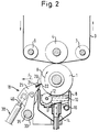
- a rake arrangement 18 is provided behind the ink tank 8 in the direction of rotation , which is used to press a doctor blade formed in the present case by a thin metal strip 20 along a surface line parallel to the axis of rotation of the forme cylinder 1 in such a way that the doctor blade band 20 clings to the former with its ground edge 22 facing the forme cylinder 1.
- the invention is Doctor blade arrangement 18 is positioned with respect to the forme cylinder in such a way that the line of contact of the doctor blade edge 22 with the outer surface of the forme cylinder 1 is below the horizontal maximum diameter of the forme cylinder 1. In this way, the amount and thus also the dynamic pressure of the ink (not shown) can be reduced, which accumulates under the doctor blade due to the rotational movement of the forme cylinder 1 and the wiping action of the squeegee belt 20 and which tries to lift it off from the outer surface of the forme cylinder 1.
- the doctor blade 20 is held in a slot 24 of the doctor bar 25, the width of which is slightly greater than the thickness of the doctor blade 20.
- the width of the slot 24 and the thickness of the squeegee band 20 are shown enlarged in FIG. 2 with respect to the remaining parts.
- the doctor blade band 22 Due to the dynamic pressure of the accumulated ink and the friction on the forme cylinder 1, the doctor blade band 22 is tilted somewhat in the slot 24, so that it is in the front area facing the forme cylinder 1 with its top side and in the rear area facing away from the forme cylinder 1 with its underside on the respective diaphragm wall is present.
- the two diaphragm walls are ground, so that the doctor blade 20 can be moved in the longitudinal direction against the diaphragm walls without excessive force during printing.
- the winding devices 28, 29 shown in FIG. 1 are provided, which can be rotated by drive devices, not shown, in such a way that one of them winds up the squeegee tape to the extent that it is unwound from the other winding device .
- the double arrows S indicate that the direction of this winding movement and thus also the longitudinal movement direction of the doctor blade 20 can be reversed.
- a guide arrangement 30, 31 consisting of two rotatable rollers is provided between each of the two winding devices 28, 29 and the squeegee bar 25.
- the rollers of these guide arrangements can either run freely with the doctor blade 20 or preferably serve to drive the doctor blade 20, so that a uniform rotational speed can be worked for a uniform movement of the doctor blade 20 in the longitudinal direction.
- the guide device to the side of which the squeegee belt moves, can in each case be driven somewhat faster than the other guide device in order to keep the squeegee belt 20 in a defined longitudinal tension.
- the winding devices 28, 29 are relieved of the tensile action of the doctor blade 20. It is only necessary to drive the winding device that winds up the doctor strip at such an instantaneous speed that the doctor strip is wound up with a winding that is not too loose.
- Each of the two winding devices 28, 29 is dimensioned such that it can accommodate a length of the doctor blade 20 that is substantially greater than the axial length of the forme cylinder 1, for example equal to 200 m. Since the squeegee tape is shifted longitudinally during normal operation at a low speed, which can be in the order of a few millimeters to a few centimeters per second, periods of the order of three to ten hours can be achieved until the squeegee tape is completely off one winding device is rewound onto the other. For a longer-lasting printing operation, the winding direction can then be carried out without a noticeable interruption in the doctor blade belt movement reversed and the tape can be rewound at a speed of the same order of magnitude. In this way, even with very high print runs, it is no longer necessary to stop the printing press only because the doctor blade has to be replaced.
- the drive device is briefly switched to a higher speed in order to quickly move the damaged area out of the area of contact with the forme cylinder. Once this has been done, the doctor blade tape is rewound again at the previous low speed.
- a sensor device (not shown), it is possible to determine the position of damaged doctor blade points on the doctor blade. These positions can be stored in a memory, which ensures that whenever a defective point occurs in the area of contact with the forme cylinder 1 after the direction of the squeegee belt movement has changed, this ensures that the rewinding speed is greatly increased in order to move the defective point past the forme cylinder as quickly as possible and in this way keep the amount of waste that is produced low.
- the doctor bar 25 is connected by means of two bearing arms 32, 33, each articulated to one of its ends, to a rotatably mounted shaft 35, which extends parallel to the axis of rotation of the forme cylinder 1 and on which the ends facing away from the doctor bar 25 are connected the bearing arms 32, 33 are non-rotatably fastened.
- the squeegee bar 25, together with the winding devices 28, 29 and the squeegee belt 20 guided by it can be pivoted away from the forme cylinder 1 or thus to the forme cylinder 1 be moved that the doctor blade 20 is pressed against the outer surface with the required contact pressure.
- two pneumatic or hydraulic cylinder arrangements are provided, the piston rods 39, 40 of which are articulated on the side of the doctor bar 25 facing away from the forme cylinder 1 and spaced apart in the longitudinal direction such that the force of the cylinder arrangements 37, 38 transversely to the longitudinal direction of the Doctor blade 25 is directed.
Landscapes
- Mechanical Engineering (AREA)
- Engineering & Computer Science (AREA)
- Rotary Presses (AREA)
- Screen Printers (AREA)
- Inking, Control Or Cleaning Of Printing Machines (AREA)
- Supplying Of Containers To The Packaging Station (AREA)
- External Artificial Organs (AREA)
- Paper (AREA)
- Replacement Of Web Rolls (AREA)
- Saccharide Compounds (AREA)
- Breeding Of Plants And Reproduction By Means Of Culturing (AREA)
- Polishing Bodies And Polishing Tools (AREA)
- Crystals, And After-Treatments Of Crystals (AREA)
Applications Claiming Priority (2)
| Application Number | Priority Date | Filing Date | Title |
|---|---|---|---|
| DE4242582 | 1992-12-16 | ||
| DE4242582A DE4242582C2 (de) | 1992-12-16 | 1992-12-16 | Rakelanordnung |
Publications (2)
| Publication Number | Publication Date |
|---|---|
| EP0602431A1 true EP0602431A1 (fr) | 1994-06-22 |
| EP0602431B1 EP0602431B1 (fr) | 2000-02-02 |
Family
ID=6475512
Family Applications (1)
| Application Number | Title | Priority Date | Filing Date |
|---|---|---|---|
| EP93119115A Expired - Lifetime EP0602431B1 (fr) | 1992-12-16 | 1993-11-26 | Dispositif de racle d'essuyage |
Country Status (10)
| Country | Link |
|---|---|
| US (1) | US5437227A (fr) |
| EP (1) | EP0602431B1 (fr) |
| JP (1) | JP2777968B2 (fr) |
| AT (1) | ATE189424T1 (fr) |
| CA (1) | CA2111427C (fr) |
| CZ (1) | CZ286937B6 (fr) |
| DE (2) | DE4242582C2 (fr) |
| FI (1) | FI107900B (fr) |
| HU (1) | HU214713B (fr) |
| PL (1) | PL173223B1 (fr) |
Families Citing this family (16)
| Publication number | Priority date | Publication date | Assignee | Title |
|---|---|---|---|---|
| DE4402226C2 (de) * | 1994-01-27 | 1997-11-06 | Voith Gmbh J M | Rakelvorrichtung |
| DE19536765C2 (de) * | 1995-10-02 | 2000-08-31 | Tampoprint Gmbh | Farbgebersystem für eine Druckmaschine |
| FR2778365B1 (fr) * | 1998-05-11 | 2000-12-15 | Jean Claude Sarda | Perfectionnements apportes aux encriers des presses a imprimer et a leur mode de nettoyage |
| US6823794B2 (en) * | 2001-06-25 | 2004-11-30 | Bosler Designs, Inc. | System and method for printing an extruded sheet |
| EP1344646B1 (fr) * | 2002-03-14 | 2004-08-11 | OFFICINE MECCANICHE GIOVANNI CERUTTI S.p.A. | Méthode pour nettoyer un dispositif d'impression pour une machine d'impression rotative en creux |
| DK1683633T3 (da) | 2005-01-24 | 2011-12-05 | Gallus Ferd Rueesch Ag | Dybtrykværk til påtrykning af en påtrykningsstofbane i en trykkemaskine |
| DE102005003206A1 (de) * | 2005-01-24 | 2006-07-27 | Gallus Ferd. Rüesch AG | Tiefdruckwerk zum Bedrucken einer Bedruckstoffbahn in einer Druckmaschine |
| EP1764216A1 (fr) * | 2005-09-16 | 2007-03-21 | Kba-Giori S.A. | Appareil pour appliquer un revêtement sur un cylindre, en particulier sur un cylindre d'essuyage d'une machine d'impression en creux |
| JP2010088968A (ja) * | 2008-10-03 | 2010-04-22 | Voith Patent Gmbh | ブレードコータのブレード交換装置 |
| JP5354358B2 (ja) * | 2009-04-24 | 2013-11-27 | 大日本印刷株式会社 | ドクタ装置 |
| JP5620729B2 (ja) * | 2010-07-08 | 2014-11-05 | 信久 山田 | ドクタ装置及びインキ掻き落とし方法 |
| DE102011120996A1 (de) | 2011-12-14 | 2013-06-20 | Gallus Stanz- Und Druckmaschinen Gmbh | Tiefdruckwerk mit Spritzschutzeinrichtung |
| DE102011121319A1 (de) | 2011-12-16 | 2013-06-20 | Gallus Stanz- Und Druckmaschinen Gmbh | Tiefdruckwerk mit Bahnspannungsausgleich und Verfahren zum Warten eines solchen Tiefdruckwerks |
| CN103331990B (zh) * | 2013-07-16 | 2014-12-17 | 大理美登印务有限公司 | 一种凹印机改进型刮墨刀锁紧调节装置 |
| DE102019102537A1 (de) * | 2019-02-01 | 2020-08-06 | TKM Meyer GmbH | Verfahren zur automatisierten Zuführung einer Rakel und Rakelvorrichtung zur Durchführung des Verfahrens |
| CN113211971B (zh) * | 2021-06-11 | 2021-11-30 | 丰县鑫牧网络科技有限公司 | 印刷机用刮墨组件 |
Citations (4)
| Publication number | Priority date | Publication date | Assignee | Title |
|---|---|---|---|---|
| DE228215C (fr) * | ||||
| FR1218756A (fr) * | 1959-03-06 | 1960-05-12 | Racle pour cylindre d'impression en héliogravure | |
| DE3428073A1 (de) * | 1984-07-30 | 1986-01-30 | Bertold Dipl.-Ing. 5503 Konz Hein | Kurzfarbwerk mit zahnrakel fuer hoch- und flachdruckmaschinen |
| DE9017689U1 (de) * | 1990-07-24 | 1991-08-08 | Koenig & Bauer AG, 8700 Würzburg | Rakelmesserband |
Family Cites Families (8)
| Publication number | Priority date | Publication date | Assignee | Title |
|---|---|---|---|---|
| US2148455A (en) * | 1937-05-06 | 1939-02-28 | Miehle Printing Press & Mfg | Gravure printing-press doctor blade construction |
| GB484756A (en) * | 1937-05-06 | 1938-05-10 | Miehle Printing Pressand Mfg C | Doctor-blade constructions for gravure printing-presses |
| DE1177653B (de) * | 1960-04-28 | 1964-09-10 | George Edmond Brackenbury Abel | Wischvorrichtung fuer Druckmaschinenzylinder |
| CH415694A (de) * | 1963-12-06 | 1966-06-30 | Giori Gualtiero | Wischvorrichtung für Stahlstichdruckmaschinen |
| US3888172A (en) * | 1973-06-21 | 1975-06-10 | American Bank Note Co | Intaglio printing press with web wiping apparatus having supply and take-up reels outside frame |
| DE2555993C3 (de) * | 1975-12-12 | 1980-11-06 | Koenig & Bauer Ag, 8700 Wuerzburg | Farbkasten eines Farbwerkes |
| EP0257818B2 (fr) * | 1986-08-02 | 1999-09-29 | Dai Nippon Insatsu Kabushiki Kaisha | Système de nettoyage pour une presse à imprimer |
| DE3919087A1 (de) * | 1989-06-10 | 1990-12-13 | Voith Gmbh J M | Streicheinrichtung |
-
1992
- 1992-12-16 DE DE4242582A patent/DE4242582C2/de not_active Expired - Fee Related
-
1993
- 1993-11-26 DE DE59309944T patent/DE59309944D1/de not_active Expired - Fee Related
- 1993-11-26 EP EP93119115A patent/EP0602431B1/fr not_active Expired - Lifetime
- 1993-11-26 AT AT93119115T patent/ATE189424T1/de not_active IP Right Cessation
- 1993-12-09 US US08/163,704 patent/US5437227A/en not_active Expired - Fee Related
- 1993-12-13 CZ CZ19932729A patent/CZ286937B6/cs not_active IP Right Cessation
- 1993-12-14 PL PL93301481A patent/PL173223B1/pl unknown
- 1993-12-14 CA CA002111427A patent/CA2111427C/fr not_active Expired - Fee Related
- 1993-12-15 HU HU9303590A patent/HU214713B/hu not_active IP Right Cessation
- 1993-12-15 FI FI935631A patent/FI107900B/fi active
- 1993-12-16 JP JP5343637A patent/JP2777968B2/ja not_active Expired - Lifetime
Patent Citations (4)
| Publication number | Priority date | Publication date | Assignee | Title |
|---|---|---|---|---|
| DE228215C (fr) * | ||||
| FR1218756A (fr) * | 1959-03-06 | 1960-05-12 | Racle pour cylindre d'impression en héliogravure | |
| DE3428073A1 (de) * | 1984-07-30 | 1986-01-30 | Bertold Dipl.-Ing. 5503 Konz Hein | Kurzfarbwerk mit zahnrakel fuer hoch- und flachdruckmaschinen |
| DE9017689U1 (de) * | 1990-07-24 | 1991-08-08 | Koenig & Bauer AG, 8700 Würzburg | Rakelmesserband |
Also Published As
| Publication number | Publication date |
|---|---|
| EP0602431B1 (fr) | 2000-02-02 |
| CA2111427A1 (fr) | 1994-06-17 |
| FI935631A0 (fi) | 1993-12-15 |
| FI107900B (fi) | 2001-10-31 |
| JPH06278263A (ja) | 1994-10-04 |
| HU9303590D0 (en) | 1994-04-28 |
| US5437227A (en) | 1995-08-01 |
| DE4242582A1 (de) | 1994-06-23 |
| DE59309944D1 (de) | 2000-03-09 |
| DE4242582C2 (de) | 1998-03-19 |
| CZ272993A3 (en) | 1994-07-13 |
| PL301481A1 (en) | 1994-06-27 |
| JP2777968B2 (ja) | 1998-07-23 |
| CZ286937B6 (en) | 2000-08-16 |
| HUT69466A (en) | 1995-09-28 |
| FI935631A7 (fi) | 1994-06-17 |
| CA2111427C (fr) | 1999-08-17 |
| HU214713B (hu) | 1998-05-28 |
| PL173223B1 (pl) | 1998-02-27 |
| ATE189424T1 (de) | 2000-02-15 |
Similar Documents
| Publication | Publication Date | Title |
|---|---|---|
| EP0064270B1 (fr) | Dispositif d'encrage | |
| DE2323025C3 (de) | Farbwerk für eine Druckmaschine | |
| EP0462490B2 (fr) | Système de mouillage à film pour presse rotative | |
| DE4242582C2 (de) | Rakelanordnung | |
| CH626000A5 (fr) | ||
| DE2648098B2 (de) | Farbkasten für Offset- oder Hochdruckmaschinen | |
| DE3623590A1 (de) | Filmfeuchtwerk fuer offsetdruckmaschinen | |
| EP0116176B1 (fr) | Dispositif d'encrage | |
| EP0019073B1 (fr) | Dispositif d'encrage pour machine à imprimer | |
| DE3401886C2 (fr) | ||
| DE2438668A1 (de) | Einfaerbvorrichtung fuer mit fetten farben arbeitende druckmaschinen | |
| WO1984003847A1 (fr) | Dispositif de raclage | |
| DE2812998C2 (de) | Vorrichtung zum Bilden eines gleichmäßigen Flüssigkeitsfilms auf einer Walze | |
| DE3714160A1 (de) | Farbwerk fuer eine druckmaschine | |
| EP0620784B1 (fr) | Presse rotative | |
| DE8401569U1 (de) | Farbwerk zur Einfärbung der Platte eines Plattenzylinders von Rotationsdruckmashinen | |
| DE3637460A1 (de) | Druckplattenbefeuchtungsvorrichtung | |
| DE3539254A1 (de) | Offset-druckerpresse | |
| EP0046951A1 (fr) | Dispositif de la couche comportant un pochoir cylindrique ou analogue et un rouleau applicateur dans celui-ci | |
| DE2101085A1 (de) | Rakelrolle | |
| DE8510718U1 (de) | Vorrichtung zum leichteren Einsetzen und Herausnehmen der Walze bei Umkehr-Tiefdruckmaschinen | |
| DE3129251A1 (de) | Vorrichtung zur regulierung des auftragsgewichtes von beschichtungen auf in laufender bahn gefuehrtem material | |
| DE3433942C1 (de) | Farbkasten fuer eine Rotationsdruckmaschine | |
| DE2258893C3 (de) | Vorrichtung zum Bedrucken von Warenbahnen, wie Teppichen o.dgl. großer Breite mittels eines Siebdruckschablonenbandes | |
| DE3526308C2 (fr) |
Legal Events
| Date | Code | Title | Description |
|---|---|---|---|
| PUAI | Public reference made under article 153(3) epc to a published international application that has entered the european phase |
Free format text: ORIGINAL CODE: 0009012 |
|
| 17P | Request for examination filed |
Effective date: 19940421 |
|
| AK | Designated contracting states |
Kind code of ref document: A1 Designated state(s): AT BE CH DE ES FR GB IT LI NL |
|
| 17Q | First examination report despatched |
Effective date: 19950703 |
|
| GRAG | Despatch of communication of intention to grant |
Free format text: ORIGINAL CODE: EPIDOS AGRA |
|
| GRAG | Despatch of communication of intention to grant |
Free format text: ORIGINAL CODE: EPIDOS AGRA |
|
| GRAH | Despatch of communication of intention to grant a patent |
Free format text: ORIGINAL CODE: EPIDOS IGRA |
|
| GRAH | Despatch of communication of intention to grant a patent |
Free format text: ORIGINAL CODE: EPIDOS IGRA |
|
| GRAA | (expected) grant |
Free format text: ORIGINAL CODE: 0009210 |
|
| AK | Designated contracting states |
Kind code of ref document: B1 Designated state(s): AT BE CH DE ES FR GB IT LI NL |
|
| PG25 | Lapsed in a contracting state [announced via postgrant information from national office to epo] |
Ref country code: NL Free format text: LAPSE BECAUSE OF FAILURE TO SUBMIT A TRANSLATION OF THE DESCRIPTION OR TO PAY THE FEE WITHIN THE PRESCRIBED TIME-LIMIT Effective date: 20000202 Ref country code: GB Free format text: LAPSE BECAUSE OF FAILURE TO SUBMIT A TRANSLATION OF THE DESCRIPTION OR TO PAY THE FEE WITHIN THE PRESCRIBED TIME-LIMIT Effective date: 20000202 Ref country code: ES Free format text: THE PATENT HAS BEEN ANNULLED BY A DECISION OF A NATIONAL AUTHORITY Effective date: 20000202 |
|
| REF | Corresponds to: |
Ref document number: 189424 Country of ref document: AT Date of ref document: 20000215 Kind code of ref document: T |
|
| REG | Reference to a national code |
Ref country code: CH Ref legal event code: EP |
|
| ITF | It: translation for a ep patent filed | ||
| REF | Corresponds to: |
Ref document number: 59309944 Country of ref document: DE Date of ref document: 20000309 |
|
| REG | Reference to a national code |
Ref country code: CH Ref legal event code: NV Representative=s name: BOVARD AG PATENTANWAELTE |
|
| ET | Fr: translation filed | ||
| NLV1 | Nl: lapsed or annulled due to failure to fulfill the requirements of art. 29p and 29m of the patents act | ||
| GBV | Gb: ep patent (uk) treated as always having been void in accordance with gb section 77(7)/1977 [no translation filed] |
Effective date: 20000202 |
|
| PG25 | Lapsed in a contracting state [announced via postgrant information from national office to epo] |
Ref country code: AT Free format text: LAPSE BECAUSE OF NON-PAYMENT OF DUE FEES Effective date: 20001126 |
|
| PG25 | Lapsed in a contracting state [announced via postgrant information from national office to epo] |
Ref country code: BE Free format text: LAPSE BECAUSE OF NON-PAYMENT OF DUE FEES Effective date: 20001130 |
|
| PLBE | No opposition filed within time limit |
Free format text: ORIGINAL CODE: 0009261 |
|
| STAA | Information on the status of an ep patent application or granted ep patent |
Free format text: STATUS: NO OPPOSITION FILED WITHIN TIME LIMIT |
|
| 26N | No opposition filed | ||
| BERE | Be: lapsed |
Owner name: U.E. SEBALD DRUCK UND VERLAG G.M.B.H. Effective date: 20001130 |
|
| PGFP | Annual fee paid to national office [announced via postgrant information from national office to epo] |
Ref country code: FR Payment date: 20011119 Year of fee payment: 9 |
|
| PGFP | Annual fee paid to national office [announced via postgrant information from national office to epo] |
Ref country code: CH Payment date: 20011126 Year of fee payment: 9 |
|
| PGFP | Annual fee paid to national office [announced via postgrant information from national office to epo] |
Ref country code: DE Payment date: 20020131 Year of fee payment: 9 |
|
| PG25 | Lapsed in a contracting state [announced via postgrant information from national office to epo] |
Ref country code: LI Free format text: LAPSE BECAUSE OF NON-PAYMENT OF DUE FEES Effective date: 20021130 Ref country code: CH Free format text: LAPSE BECAUSE OF NON-PAYMENT OF DUE FEES Effective date: 20021130 |
|
| PG25 | Lapsed in a contracting state [announced via postgrant information from national office to epo] |
Ref country code: DE Free format text: LAPSE BECAUSE OF NON-PAYMENT OF DUE FEES Effective date: 20030603 |
|
| REG | Reference to a national code |
Ref country code: CH Ref legal event code: PL |
|
| PG25 | Lapsed in a contracting state [announced via postgrant information from national office to epo] |
Ref country code: FR Free format text: LAPSE BECAUSE OF NON-PAYMENT OF DUE FEES Effective date: 20030731 |
|
| REG | Reference to a national code |
Ref country code: FR Ref legal event code: ST |
|
| PG25 | Lapsed in a contracting state [announced via postgrant information from national office to epo] |
Ref country code: IT Free format text: LAPSE BECAUSE OF NON-PAYMENT OF DUE FEES Effective date: 20051126 |