EP0602438A1 - Récepteur pour radiodiffusion RDS - Google Patents
Récepteur pour radiodiffusion RDS Download PDFInfo
- Publication number
- EP0602438A1 EP0602438A1 EP93119152A EP93119152A EP0602438A1 EP 0602438 A1 EP0602438 A1 EP 0602438A1 EP 93119152 A EP93119152 A EP 93119152A EP 93119152 A EP93119152 A EP 93119152A EP 0602438 A1 EP0602438 A1 EP 0602438A1
- Authority
- EP
- European Patent Office
- Prior art keywords
- broadcast transmission
- transmission signal
- category
- receiving
- program
- Prior art date
- Legal status (The legal status is an assumption and is not a legal conclusion. Google has not performed a legal analysis and makes no representation as to the accuracy of the status listed.)
- Granted
Links
Images


Classifications
-
- H—ELECTRICITY
- H04—ELECTRIC COMMUNICATION TECHNIQUE
- H04H—BROADCAST COMMUNICATION
- H04H20/00—Arrangements for broadcast or for distribution combined with broadcast
- H04H20/28—Arrangements for simultaneous broadcast of plural pieces of information
- H04H20/33—Arrangements for simultaneous broadcast of plural pieces of information by plural channels
- H04H20/34—Arrangements for simultaneous broadcast of plural pieces of information by plural channels using an out-of-band subcarrier signal
-
- H—ELECTRICITY
- H04—ELECTRIC COMMUNICATION TECHNIQUE
- H04H—BROADCAST COMMUNICATION
- H04H40/00—Arrangements specially adapted for receiving broadcast information
- H04H40/18—Arrangements characterised by circuits or components specially adapted for receiving
- H04H40/27—Arrangements characterised by circuits or components specially adapted for receiving specially adapted for broadcast systems covered by groups H04H20/53 - H04H20/95
-
- H—ELECTRICITY
- H04—ELECTRIC COMMUNICATION TECHNIQUE
- H04H—BROADCAST COMMUNICATION
- H04H2201/00—Aspects of broadcast communication
- H04H2201/10—Aspects of broadcast communication characterised by the type of broadcast system
- H04H2201/13—Aspects of broadcast communication characterised by the type of broadcast system radio data system/radio broadcast data system [RDS/RBDS]
Definitions
- the present invention relates to radio receivers and specifically to radio receivers for receiving Radio Data System (RDS) broadcasts.
- RDS Radio Data System
- Radio Data System (RDS) broadcasts are special types of radio broadcasts that are widely implemented in Europe. RDS broadcast transmissions incorporate several types of information in addition to the audio content of the program that is broadcast.
- PTY program type display
- the PTY code is used to inform the listener of the general category of the program of the particular station to which an RDS receiver is tuned. For example, the category might be news, music, drama, educational, scientific, etc.
- RDS signals Another type of information incorporated in RDS signals represents the identity of the specific program being received.
- the program is identified by program identification codes (PI codes).
- PI codes program identification codes
- a number of broadcasters may be transmitting the same program at different receivable frequencies, each having the same PI code.
- different programs with different PI codes, each in the same category and thus having the same PTY code could be airing simultaneously.
- RDS broadcasters may also transmit a list, called an AF list, which correlates the freqencies of RDS broadcasters and PI codes of the broadcasts at each frequency.
- the PTY function shows, on a display, the category of the program being received.
- the display permits the user to select a station based on the general program content.
- the additional equipment in RDS receivers for performing the PTY function serves no special purpose at times when no program in the selected category is broadcasting. For example, such recievers require a key switch for the PTY function. This requirement increases the number of keys and thereby the difficulty of operation.
- An object of the present invention is to provide a Radio Data System (RDS) receiver that overcomes the drawbacks of the prior art.
- RDS Radio Data System
- Another object of the present invention is to provide an RDS receiver that makes additional active use of equipment for the Program Type Display (PTY) function to enhance the functionality of the receiver.
- PY Program Type Display
- Still another object of the present invention is to provide an RDS receiver that can automatically tune to a station broadcasting a desired program.
- Still another object of the present invention is to provide an RDS receiver that can automatically tune to a station broadcasting a desired general category of program.
- Still another object of the present invention is to provide an RDS receiver that can automatically tune to a station transmitting the strongest signal.
- Still another object of the present invention is to provide and RDS receiver with high operability, functionality and convenience.
- a Radio Data Systems (RDS) receiver has a decoder circuit to read RDS data from a broadcast transmission signal. From the RDS data, a control circuit determines a program of the received signal, a program category of the received signal, lists of programs and program categories of other stations, and a regional digit.
- the receiver has a controller to store a desired program category.
- the RDS data is used to control the receiver to perform several different functions.
- the receiver will interrupt reception of a signal, the category of which is different from a desired category and receive a signal that matches the desired category.
- the receiver will revert to a previous program when the category of the signal to which it switched no longer matches the desired category.
- the receiver will revert to the strongest signal having one of a specified set of regional digits.
- the receiver also permits the storage of a desired category using only an RDS key and at least one other key.
- an RDS receiver comprising: means for receiving a broadcast transmission signal, the means for receiving including means for deriving a first audio signal from the broadcast transmission signal, means for determining a broadcast category of the broadcast transmission signal, controller means for storing a desired category, the controller means including means for activating an interrupt mode of the controller means, means for generating a second audio signal, the controller means including means for outputting the second audio signal and the controller means including means for outputting the first audio signal when the interrupt mode is activated and a desired category, stored in the controller means, matches the broadcast category of the broadcast transmission signal.
- an RDS receiver comprising: tuner means for receiving a broadcast transmission signal, the tuner means including means for deriving a first audio signal from the broadcast transmission signal, means for extracting a data signal from the broadcast transmission signal, the data signal including data indicating a broadcast program of the broadcast transmission signal, controller means for storing a desired program in a memory of the controller means, the controller means including input means for activating an interrupt mode of the controller means, means for generating a second audio signal, the controller means including means for outputting the first audio signal when the interrupt mode is activated and a desired program, stored in the memory, matches the broadcast program of the broadcast transmission signal.
- an RDS receiver comprising: means for receiving broadcast transmission signals, means for monitoring a category of a first one of the broadcast transmission signals, controller means for storing a desired category, controller means including means for activating an interrupt mode of the controller means, the controller means including means for tuning the means for receiving to receive a first one of the broadcast transmission signals, the controller means including means for tuning the means for receiving to receive the second one of the broadcast transmission signals when the interrupt mode is activated and a stored desired category matches the first one category.
- an RDS receiver comprising: means for receiving broadcast transmission signals, each having a category, controller means for tuning the means for receiving to receive a first one of the broadcast transmission signals, the controller means including means for storing a desired category, means for determining a category of at least another of the broadcast transmission signals by scanning a list of data derived from the first one, the controller means including means for activating an interrupt mode of the controller means, the controller means including means for tuning the means for receiving to receive the at least another when the interrupt mode is activated and a stored desired category matches the at least another category.
- an RDS receiver comprising: means for receiving broadcast transmission signals, each of the broadcast transmission signal having a category, means for storing a desired category, controller means for monitoring a first broadcast transmission signal category and the controller means including means for scanning others of the broadcast transmission signal categories and the controller means including means for tuning the means for receiving to receive one of the others when the one category matches a stored desired category.
- an RDS receiver comprising: means for storing a desired category, means for receiving broadcast transmission signals each having a program and a category, controller means for tuning the means for receiving to receive a first one of the broadcast transmission signals after receiving a second one of the broadcast transmission signals when the second one matching a stored desired category, the controller means including means for activating an interrupt mode of the controller means, means for deactivating the interrupt mode when the first one category changes, the controller means including means for confirming a receivability of the second one after the first one category changes and the controller means including means for subsequently tuning the means for receiving to receive the second one when the receivability is confirmed.
- a method for controlling a receiver comprising the steps of: storing a desired category, generating a first audio signal from a first audio source, outputting the first audio signal, monitoring a category of a broadcast transmission signal, receiving the broadcast transmission signal and outputting a second audio signal derived from the broadcast transmission signal when the broadcast transmission signal category matches a stored desired category, continuing the outputting of the first audio signal when the broadcast transmission signal category is different from the desired category.
- a method for controlling a receiver comprising the steps of: storing a desired category, receiving a first broadcast transmission signal having a category, storing a frequency of the first broadcast transmission signal, monitoring a category of the broadcast transmission signal, determining categories of other broadcast transmission signals when the first broadcast transmission signal category is different from a stored desired category, receiving one of the other broadcast transmission signals and storing a frequency of the one of when the one of category matches the stored desired category, receiving the first broadcast transmission signal when all of the other broadcast transmission signal categories are different from the desired category.
- a method for controlling a receiver comprising the steps of: storing a desired category, receiving a first broadcast transmission signal containing encoded data indicating categories of other broadcast transmission signals, monitoring a category of the first broadcast transmission signal, continuing the receiving of the first broadcast transmission signal while the first broadcast transmission signal category matches a stored desired category, scanning the encoded data to determine if one of the other broadcast transmission signal categories matches the stored desired category and receiving the one of when the first broadcast transmission signal category is different from the desired category, displaying the stored desired category.
- a method for controlling a receiver comprising the steps of: storing a desired category, receiving a first broadcast transmission signal, monitoring a category of the first broadcast transmission signal, continuing to receive the first broadcast transmission signal while the first broadcast transmission signal category matches a stored desired category, consecutively receiving and checking categories of other broadcast transmission signals to determine if one of the other broadcast transmission signal categories matches the stored desired category when the first broadcast transmission signal category is different from the stored desired category, receiving one of the other broadcast transmission signals when the one of category matches the stored desired category and the first broadcast transmission signal category is different from the stored desired category; and displaying the stored desired category.
- a method for controlling a receiver comprising the steps of: storing a desired category, receiving a first broadcast transmission signal, the first broadcast transmission signal having a program, storing the first broadcast transmission signal program, receiving a second broadcast transmission signal having a category matching a stored desired category, monitoring the second broadcast transmission signal category, continuing the receiving while the first broadcast transmission signal category matches the stored desired category, confirming a receivability of the first broadcast transmission signal when the first broadcast transmission signal category is different from the desired category, receiving the first broadcast transmission signal when the receivability is confirmed and receiving an alternative broadcast transmission signal when the first broadcast transmission signal when the receivability is unconfirmed.
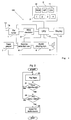
- Fig. 1 is a block diagram of a Radio Data System (RDS) receiver according to an embodiment of the present invention.
- RDS Radio Data System
- Fig. 2 is a flowchart showing a portion of the operating sequence of the receiver of Fig. 1 according to an embodiment of the present invention in which the receiver switches from a tape player source to an FM broadcast source if a PTY code indicates a desired category of broadcast is being received.
- Fig. 3 is a flowchart showing a portion of the operating sequence of the receiver of Fig. 1 according to another embodiment of the present invention in which the receiver switches to a new station if the one being received does not match a selected PTY code.
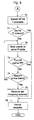
- Fig. 4 is a flowchart showing a portion of the operating sequence of the receiver of Fig. 1 according to still another embodiment of the present invention in which a PTY category is selected by a user using key switches provided on the receiver.
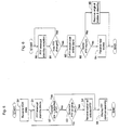
- Fig. 5 is a flowchart showing a portion of the operating sequence of the receiver of Fig. 1 according to still another embodiment of the present invention in which the receiver switches to a new station if the one being received does not match a selected PTY code.
- Fig. 6 is a flowchart showing a portion of the operating sequence of the receiver of Fig. 1 according to still another embodiment of the present invention in which the receiver searches the FM band for a broadcast whose PTY code is the same as a selected PTY code.
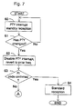
- Fig. 7 is a flowchart showing a portion of the operating sequence of the receiver of Fig. 1 according to still another embodiment of the present invention in which the receiver switches to another station if the PTY code changes and determines if a PI code can be read from a station previously received.
- Fig. 8 is a flowchart showing a portion of the operating sequence of the receiver of Fig. 1 according to still another embodiment of the present invention in which the receiver searches for an alternative broadcast if it can't find one with an identical PI code.
- Fig. 9 is a flowchart showing a portion of the operating sequence of the receiver of Fig. 1 according to still another embodiment of the present invention in which the receiver searches for an alternative broadcast if it can't find one with an identical PI code.
- a Radio Data System (RDS) receiver 100 includes an FM tuner 1, with an antenna 1a, which receives an RDS broadcast transmission signal.
- An encoded RDS signal is derived from the RDS broadcast transmission signal by an RDS decoder 2.
- RDS decoder 2 outputs the RDS signal to a CPU 3.
- Command signals are sent to CPU 3 through a connected keyboard 4.
- Keyboard 4 includes an RDS key 10, a tune up/down key 11 and a preset key 12.
- CPU 3 outputs a variety of messages to a connected display 5.
- An audio signal from FM tuner 1 is sent to a connected source selection switch 6.
- RDS receiver 100 contains a tape player 7 that sends an audio signal to source selection switch 6.
- Source selection switch 6 selects one of the audio signals from tape player 7 and FM tuner 1 for application to an input of an audio playing system 8.
- Audio playing system 8 demodulates and amplifies the selected audio signal to generate an output signal.
- the output signal of audio playing system 8 drives a speaker 9 to produce an audible signal.
- CPU 3 sends control signals to source selection switch 6 through a control line to control it.
- CPU 3 also sends control signals to tuner 1 through a control line to tune it to specific frequencies.
- CPU 3 can support a function called program type display (PTY) which permits a user to select a desired category of program for listening. For example, the user may select one of news, music, drama, and educational categories.
- the RDS signal is a stream of RDS data derived from the RDS broadcast transmission signals by RDS decoder 2. These data are included in the RDS signal sent to CPU 3 by RDS decoder 2. Among the RDS data are PTY codes, which identify the program category of the RDS broadcast transmission being received by tuner 1.
- RDS receiver 100 To cause RDS receiver 100 to tune to a broadcast with a desired program content, the user makes a PTY item, which represents the desired program category, using display 5 and keyboard 4. A PTY standby mode is selected through keyboard 4, which causes CPU 3 to search for an RDS broadcast transmission signal bearing a PTY code corresponding to the PTY item selected. If CPU 3 finds a transmission bearing the correct PTY code, it will adjust tuner 1 to receive the transmission.
- CPU 3 first determines if a news standby operation was selected through keyboard 4 in step 21. If news standby operation was selected, the RDS data received by FM tuner 1 is checked in step 22. If the content of the broadcast being received is news, source selection circuit 6 is switched from tape player 7 to FM tuner 1 in step 23.
- CPU 3 automatically switches from the received RDS broadcast to a different broadcast based on a selected operating mode and certain criteria.
- EON Enhanced Other Network
- the EON data which may be transmitted by RDS stations, provides information about the program content of other network stations besides the particular one being received. This data includes a list stations currently broadcasting, each correlated with a corresponding PTY code for the program being broadcast.
- step 30 a broadcast from a station providing EON data is received by tuner 1. Control then proceeds to step 31. If news standby mode is selected in step 31, control branches to step 32. If news standby mode is not selected, control returns to step 30. Step 32 branches to step 33 if the category of the broadcast being received is the same as the selected news category. In step 33, "NEWS" is shown on display 5, and the current station continues to be received. If the broadcast being received is not the same as the selected news category, control branches to step 34 where the EON data is scanned for another network with a matching program category. If a match is found, the corresponding station is tuned-in in step 35. In step 36, an identifier for the new station is stored in a memory. By permitting the selection of the PTY standby mode described above, this embodiment puts RDS key 10 to a use additional to its use in prior art RDS receivers, which is merely to activate the RDS display function.
- step 41 branches to step 42 if RDS key 10 is pressed for at least a specified interval (two seconds in the present embodiment). If RDS key 10 has not been pressed for at least two seconds in step 41, control returns to step 40.
- step 42 a PTY selection mode is activated and the PTY item displayed on display 5.
- step 43 branches to step 44 if tune up/tune down key 11 has been pressed or to step 45 if it has not.
- Step 45 returns to step 42 if 5 seconds have elapsed since the PTY selection mode was activated.
- control loops through 42, 43 and 45 until either 5 seconds pass, or tune up/tune down key 10 is pressed. If 5 seconds pass without the user pressing tune up/tune down key 10, control proceeds to step 46 where the PTY interrupt standby mode is activated and display 5 reverts to the original display.
- Step 44 a consecutive PTY item from a stored list of PTY items is called and displayed. Control proceeds back to step 42. If the desired PTY item was the last one to be displayed, it is selected when the five second period in step 45 runs out. If tune up/tune down key 10 is pressed, another PTY item is called up from the list and displayed. This process continues until a desired PTY item is selected by permitting the 5 second timer to run out. Note that this selection process requires no keys additional to those for setting the PTY standby mode.
- step 50 an RDS broadcast containing EON data is received in step 50.
- Control proceeds to step 51 where a PTY item is selected and PTY standby mode initiated.
- Control then proceeds to step 52, which branches to step 55 if the current station matches the PTY selected, or to step 53 if the current station's PTY code and the selected PTY item do not match.
- step 55 the selected PTY item is displayed and reception continued.
- Step 53 returns to step 51 if there is no other station in the EON link, i.e., there is no station in the list of stations whose PTY code matches the PTY item selected. If a matching station is found, tuner 1 is adjusted to receive the station in step 54. Control proceeds from step 54 to step 55 where the current PTY item is displayed and the current station is received.
- step 90 PTY standby mode is active in step 90.
- Control proceeds to step 91 which branches to step 92 if the PTY code of the current station has changed. If the PTY code of the current station has not changed, control returns to step 90.
- step 92 a search over the entire broadcast band is executed to find a station broadcasting a signal with a PTY code that matches the selected PTY code.
- step 93 a search over the entire broadcast band is executed to find a station broadcasting a signal with a PTY code that matches the selected PTY code.
- step 93 branches to step 95 if no matching PTY code is found, or to step 94 if a match is found.
- step 94 the station with the matching PTY code is received.
- step 95 the original station is received and standby operation resumed.
- step 61 it is determined if the PTY code of the program currently being received has changed. If the PTY code of the current station has changed, the PTY interrupt mode is disabled in step 62. If the PTY code of the current station has not changed, control returns to step 60. In step 62, the station that was current prior to the activation of the PTY interrupt mode is tuned in, and the PTY interrupt mode disabled, at step 62. The PI code of this station is checked in step 63 and, if the PI code can be read (confirmed), normal reception is activated. Failure to confirm the PI code indicates the signal quality is poor. When the PI code cannot be confirmed in step 63, control proceeds to either the embodiment shown in Fig. 8 or the embodiment shown in Fig. 9.
- step 70 if there is an AF list, the AF list is searched in step 70.
- An AF list is an encoded list of stations indicating the programs being broadcast by each station. The AF list may be included in the RDS data. If a signal is found in step 71, which has a PI code identical to that of that of the station received prior to activation of the PTY interrupt mode, control proceeds to step 76 where that signal is received. If no match is found, a scan for an identical PI code is performed in steps 72, 73 and 74.
- step 72 the FM frequency band is scanned to find the frequency of the next receivable signal.
- step 73 the PI code of that next receivable signal is compared to the PI code of the station selected prior to activation of the PTY interrupt mode. If a match is found, control branches to step 76 where the station with the matching PI code is tuned in. If no match is found control proceeds to step 74 which loops back to step 72 until the entire frequency band has been scanned and the corresponding PI codes of each signal checked. If no match is found after the scan of the entire band, the last frequency before the interrupt is and tuned in at step 75.
- step 80 if there is an AF list memory, the AF list memory is searched in step 80. If a signal is found in step 81, which has a PI code identical to that of the station received prior to activation of the PTY interrupt mode, control proceeds to step 89 where the matching signal is received. If no match is found, control proceeds to step 82.
- step 82 the FM band is scanned for an RDS station.
- Control proceeds to step 83 where the PI code of the new station is compared to that of that of the station received prior to activation of the PTY interrupt mode. If a match is found, control branches to step 89 where the matching station is tuned in. If no match is found in step 83, control proceeds to step 84 where it is determined if a regional digit of the signal is one of 1, 2 and 3. The regional digit is embedded in the RDS data of the signal being received. If the regional digit is the same, the signal strength at the previous frequency B is compared to that at the new frequency A in step 85. If the regional digit is different, control advances to step 87.
- step 85 if the strength of the signal at frequency A is higher, control proceeds to step 86 where the new frequency data are stored in memory location B. If the strength of the new frequency signal is lower than that of the signal stored at B, control proceeds to step 87. Step 87 returns to step 82 and the previous steps between 82 and 87 are repeated. These steps continue to be repeated for each new station until, either a matching PI code is found at step 83, or a scanning of the entire FM band is found to be completed in step 87. If the scanning of the FM band is completed without finding a matching PI code in step 83, control proceeds from step 87 to step 88. In step 88, the frequency stored in memory location B, is tuned in.
- the frequency stored in memory location B is either the frequency being received when the PTY interrupt mode was activated or a new frequency.
- the frequency stored in memory location B is a new frequency if, while cycling through steps 84 through 86, a frequency was found which had the regional digits of 1, 2 or 3 and which had a greater field strength than the original frequency. The frequency at B would then be the frequency of the signal which had the greatest field strength of all such signals.
- normal reception continues.
Landscapes
- Engineering & Computer Science (AREA)
- Signal Processing (AREA)
- Circuits Of Receivers In General (AREA)
Applications Claiming Priority (4)
| Application Number | Priority Date | Filing Date | Title |
|---|---|---|---|
| JP354036/92 | 1992-12-14 | ||
| JP4354036A JP3011351B2 (ja) | 1992-12-14 | 1992-12-14 | 多重放送受信機 |
| JP1993008994U JP2596313Y2 (ja) | 1993-02-09 | 1993-02-09 | Rds受信装置 |
| JP8994/93 | 1993-02-09 |
Publications (2)
| Publication Number | Publication Date |
|---|---|
| EP0602438A1 true EP0602438A1 (fr) | 1994-06-22 |
| EP0602438B1 EP0602438B1 (fr) | 1998-03-11 |
Family
ID=26343633
Family Applications (1)
| Application Number | Title | Priority Date | Filing Date |
|---|---|---|---|
| EP93119152A Revoked EP0602438B1 (fr) | 1992-12-14 | 1993-11-27 | Récepteur pour radiodiffusion RDS |
Country Status (3)
| Country | Link |
|---|---|
| US (1) | US5548828A (fr) |
| EP (1) | EP0602438B1 (fr) |
| DE (1) | DE69317371T2 (fr) |
Cited By (5)
| Publication number | Priority date | Publication date | Assignee | Title |
|---|---|---|---|---|
| EP0680166A1 (fr) * | 1994-04-27 | 1995-11-02 | Pioneer Electronic Corporation | Méthode de syntonisation d'un récepteur de radio diffusion utilisant les données d'identification de programme diffusées sur une sous-porteuse additionelle |
| WO1997040625A3 (fr) * | 1996-04-25 | 1997-12-04 | Philips Electronics Nv | Recepteur avec touches de preselection |
| WO1998005136A3 (fr) * | 1996-07-30 | 1998-03-19 | Bosch Gmbh Robert | Recepteur radio avec memoire pour frequences d'emission et codes affectes a ces frequences |
| EP0928953A3 (fr) * | 1998-01-07 | 2000-07-12 | CLARION Co., Ltd. | Appareil et méthode de commande d'un affichage pour une unité de navigation |
| FR2853166A1 (fr) * | 2003-03-27 | 2004-10-01 | Bosch Gmbh Robert | Appareil radio equipe d'une installation de reconnaissance de morceaux musicaux |
Families Citing this family (33)
| Publication number | Priority date | Publication date | Assignee | Title |
|---|---|---|---|---|
| JPH07321679A (ja) * | 1994-05-24 | 1995-12-08 | Pioneer Electron Corp | 多重放送選局方法及び当該方法を用いた受信機 |
| EP0716517B1 (fr) * | 1994-12-09 | 2003-06-04 | Koninklijke Philips Electronics N.V. | Système avec un dispositif pour extraire des informations supplémentaires d'un canal audiophonique, comportant un canal supplémentaire, et un générateur de pacquets produisant un deuxième canal supplémentaire pour le canal audiophonique, et un terminal pour ledit système |
| JPH08223059A (ja) * | 1995-02-16 | 1996-08-30 | Pioneer Electron Corp | 放送局関連情報を有するデータベースを備えたrbds受信装置 |
| US6088455A (en) * | 1997-01-07 | 2000-07-11 | Logan; James D. | Methods and apparatus for selectively reproducing segments of broadcast programming |
| TW377533B (en) * | 1996-11-06 | 1999-12-21 | Koninkl Philips Electronics Nv | Radio receiver for receiving a main radio broadcast signal and a monolithic integrated circuit for use in such radio receiver |
| US6324592B1 (en) | 1997-02-25 | 2001-11-27 | Keystone Aerospace | Apparatus and method for a mobile computer architecture and input/output management system |
| US6021320A (en) * | 1997-06-27 | 2000-02-01 | Delco Electronics Corporation | Broadcast receiver providing selectable categories of available broadcast signals |
| US6112064A (en) * | 1997-08-26 | 2000-08-29 | Thomson Consumer Electronics Sales, Gmbh | RDS radio with multi-function RDS button |
| US6704553B1 (en) * | 1997-10-08 | 2004-03-09 | Thomas M. Eubanks | System and method for providing automatic tuning of a radio receiver and for providing automatic control of a CD/tape player |
| US7369824B1 (en) | 1999-02-04 | 2008-05-06 | Chan Hark C | Receiver storage system for audio program |
| US6600908B1 (en) | 1999-02-04 | 2003-07-29 | Hark C. Chan | Method and system for broadcasting and receiving audio information and associated audio indexes |
| EP1032128A1 (fr) * | 1999-02-23 | 2000-08-30 | Mannesmann VDO Aktiengesellschaft | Méthode de traitement de données de transmetteur et de programme dans un récepteur FM RDS |
| US7245707B1 (en) | 1999-03-26 | 2007-07-17 | Chan Hark C | Data network based telephone messaging system |
| ATE460020T1 (de) | 2000-09-13 | 2010-03-15 | Stratosaudio Inc | System und verfahren zum bestellen und zur verfügung stellen von medieninhalten, mit verwendung von zusatzdaten die in einem rundfunksignal mitübertragen werden |
| US6785656B2 (en) * | 2001-06-05 | 2004-08-31 | Xm Satellite Radio, Inc. | Method and apparatus for digital audio playback using local stored content |
| US7054653B2 (en) * | 2001-10-04 | 2006-05-30 | Nokia Corporation | Two channel communication system based on RDS datastream broadcasting and the integration of digital mobile terminal and VHF/FM radio receiver |
| US7502589B2 (en) * | 2002-12-06 | 2009-03-10 | Bose Corporation | Supplemental broadcast data processing |
| US20040145462A1 (en) * | 2003-01-29 | 2004-07-29 | Honda Giken Kogyo Kabushiki Kaisha | Variable electronic display apparatus for a vehicle, and method of using same |
| DE10305659A1 (de) * | 2003-02-12 | 2004-08-26 | Robert Bosch Gmbh | Rundfunkempfänger mit Programmspeichern und den Programmspeichern zugeordneten oder zuordenbaren Bedienelementen |
| US7917130B1 (en) | 2003-03-21 | 2011-03-29 | Stratosaudio, Inc. | Broadcast response method and system |
| US7606327B2 (en) * | 2003-07-28 | 2009-10-20 | Delphi Technologies, Inc. | Method to receive local information with a national broadcast service |
| US7551137B2 (en) * | 2004-06-10 | 2009-06-23 | Tektrap Systems Inc. | Apparatus and method for tracing a path travelled by an entity or object, and tag for use therewith |
| US20060128418A1 (en) * | 2004-12-14 | 2006-06-15 | Nokia Corporation | Phone functions triggered by broadcast data |
| US7447488B2 (en) * | 2005-07-07 | 2008-11-04 | Bose Corporation | Broadcast signal reception enhancing |
| US20070061952A1 (en) * | 2005-09-21 | 2007-03-22 | Sheng-Mao Huang | Toilet cover and seat structure |
| US7735101B2 (en) | 2006-03-28 | 2010-06-08 | Cisco Technology, Inc. | System allowing users to embed comments at specific points in time into media presentation |
| WO2009079417A1 (fr) | 2007-12-14 | 2009-06-25 | Stratosaudio, Inc. | Systèmes et procédés de programmation de supports et d'événements interactifs |
| WO2009079416A2 (fr) | 2007-12-14 | 2009-06-25 | Stratosaudio, Inc. | Systèmes et procédés pour délivrer des supports mis à jour |
| US8166081B2 (en) | 2008-02-05 | 2012-04-24 | Stratosaudio, Inc. | System and method for advertisement transmission and display |
| US8875188B2 (en) | 2008-02-05 | 2014-10-28 | Stratosaudio, Inc. | Systems, methods, and devices for scanning broadcasts |
| US8571501B2 (en) * | 2008-04-21 | 2013-10-29 | Qualcomm Incorporated | Cellular handheld device with FM Radio Data System receiver |
| US7979068B2 (en) * | 2008-10-17 | 2011-07-12 | Motorola Solutions, Inc. | Method and device for traversing a scan list in a communication system |
| US8359192B2 (en) * | 2008-11-19 | 2013-01-22 | Lemi Technology, Llc | System and method for internet radio station program discovery |
Citations (4)
| Publication number | Priority date | Publication date | Assignee | Title |
|---|---|---|---|---|
| DE3743213A1 (de) * | 1987-12-19 | 1989-06-29 | Blaupunkt Werke Gmbh | Ukw-empfaenger |
| JPH02301330A (ja) * | 1989-05-16 | 1990-12-13 | Alpine Electron Inc | 車載用ラジオ受信機 |
| DE4031431A1 (de) * | 1989-12-06 | 1991-06-13 | Pioneer Electronic Corp | Verkehrsinformationsempfaenger |
| EP0498233A2 (fr) * | 1991-02-08 | 1992-08-12 | Blaupunkt-Werke GmbH | Récepteur radio avec RDS |
Family Cites Families (7)
| Publication number | Priority date | Publication date | Assignee | Title |
|---|---|---|---|---|
| US5152011A (en) * | 1987-07-27 | 1992-09-29 | Schwob Pierre R | Broadcast receiver capable of automatic station identification and format-scanning based on an internal database updatable via data reception over the airwaves |
| US4969209A (en) * | 1987-07-27 | 1990-11-06 | Prs Corporation | Broadcast receiver capable of selecting stations based upon geographical location and program format |
| GB8829274D0 (en) * | 1988-12-15 | 1989-01-25 | British Broadcasting Corp | Improvements to rds radio systems |
| US5239700A (en) * | 1988-12-16 | 1993-08-24 | Robert Bosch Gmbh | Multi-choice information system for a motor vehicle |
| DE3914104A1 (de) * | 1989-04-28 | 1990-11-15 | Bosch Gmbh Robert | Rundfunkempfaenger, insbesondere fahrzeugempfaenger |
| JPH0731649Y2 (ja) * | 1990-11-28 | 1995-07-19 | 船井電機株式会社 | チャンネル選局装置 |
| US5276909A (en) * | 1991-06-25 | 1994-01-04 | Autotalk, Inc. | Traffic information broadcast system |
-
1993
- 1993-11-27 DE DE69317371T patent/DE69317371T2/de not_active Revoked
- 1993-11-27 EP EP93119152A patent/EP0602438B1/fr not_active Revoked
- 1993-12-14 US US08/167,223 patent/US5548828A/en not_active Expired - Lifetime
Patent Citations (4)
| Publication number | Priority date | Publication date | Assignee | Title |
|---|---|---|---|---|
| DE3743213A1 (de) * | 1987-12-19 | 1989-06-29 | Blaupunkt Werke Gmbh | Ukw-empfaenger |
| JPH02301330A (ja) * | 1989-05-16 | 1990-12-13 | Alpine Electron Inc | 車載用ラジオ受信機 |
| DE4031431A1 (de) * | 1989-12-06 | 1991-06-13 | Pioneer Electronic Corp | Verkehrsinformationsempfaenger |
| EP0498233A2 (fr) * | 1991-02-08 | 1992-08-12 | Blaupunkt-Werke GmbH | Récepteur radio avec RDS |
Non-Patent Citations (2)
| Title |
|---|
| "Specifications of the Radio Data System RDS for VHF/FM sound broadcasting, Programme type codes", EUROPEAN BROADCASTING UNION, July 1989 (1989-07-01), BRUXELLES, BE * |
| PATENT ABSTRACTS OF JAPAN vol. 15, no. 086 (E - 1039) 28 February 1991 (1991-02-28) * |
Cited By (7)
| Publication number | Priority date | Publication date | Assignee | Title |
|---|---|---|---|---|
| EP0680166A1 (fr) * | 1994-04-27 | 1995-11-02 | Pioneer Electronic Corporation | Méthode de syntonisation d'un récepteur de radio diffusion utilisant les données d'identification de programme diffusées sur une sous-porteuse additionelle |
| US5802066A (en) * | 1994-04-27 | 1998-09-01 | Pioneer Electronic Corporation | Multiplex broadcast receiving method and receiver with program type memory |
| WO1997040625A3 (fr) * | 1996-04-25 | 1997-12-04 | Philips Electronics Nv | Recepteur avec touches de preselection |
| WO1998005136A3 (fr) * | 1996-07-30 | 1998-03-19 | Bosch Gmbh Robert | Recepteur radio avec memoire pour frequences d'emission et codes affectes a ces frequences |
| EP0928953A3 (fr) * | 1998-01-07 | 2000-07-12 | CLARION Co., Ltd. | Appareil et méthode de commande d'un affichage pour une unité de navigation |
| US6268837B1 (en) | 1998-01-07 | 2001-07-31 | Clarion Co., Ltd | Display control device and method |
| FR2853166A1 (fr) * | 2003-03-27 | 2004-10-01 | Bosch Gmbh Robert | Appareil radio equipe d'une installation de reconnaissance de morceaux musicaux |
Also Published As
| Publication number | Publication date |
|---|---|
| DE69317371T2 (de) | 1998-11-19 |
| DE69317371D1 (de) | 1998-04-16 |
| EP0602438B1 (fr) | 1998-03-11 |
| US5548828A (en) | 1996-08-20 |
Similar Documents
| Publication | Publication Date | Title |
|---|---|---|
| US5548828A (en) | RDS audio receiver having interrupt mode | |
| US8792842B2 (en) | Searching receiver | |
| US6711390B1 (en) | Program related data in an FM RDS receiver | |
| US5535442A (en) | FM tuner having improved tuning speed | |
| EP1181775B1 (fr) | Procede de selection d'une frequence de mise au point de recepteur | |
| EP1755219B1 (fr) | Récepteur de radiodiffusion à multiplexage de données à plusieurs tuners | |
| GB2259204A (en) | Audio system with fm broadcasting receiver having means to indicate type of program received | |
| JP3279379B2 (ja) | ラジオ受信機 | |
| EP1013016A1 (fr) | Procede de stockage de donnees de frequences alternatives destine a un recepteur rds et appareil con u a cet effet | |
| JPH10507609A (ja) | 放送局のデジタルデータテレグラムで伝送される放送局名とプログラム種別を放送受信機ディスプレイに表示するための方法および装置 | |
| JPH01125128A (ja) | Rds受信機 | |
| JP3295531B2 (ja) | Rds受信機 | |
| JPH02213229A (ja) | Rdsの自動追従方法 | |
| JP2709588B2 (ja) | デジタルデータ多重システムの受信方法 | |
| EP0688112B1 (fr) | Méthode dans un récepteur RDS pour contrôler l'interruption d'un programme | |
| JP3135763B2 (ja) | 多重放送受信機 | |
| EP0986199B1 (fr) | Récepteur pour la réception de programmes de radiodiffusion numérique DAB | |
| EP0552442B1 (fr) | Récepteur pour système RDS | |
| JPH0326103A (ja) | データ多重ラジオ放送の受信装置 | |
| JPH01276828A (ja) | Rds受信方法 | |
| KR0148003B1 (ko) | 광역 라디오 데이타 시스템 수신기 및 수신방법 | |
| JP3246525B2 (ja) | 受信機 | |
| JP2647670B2 (ja) | 受信機 | |
| JP3336565B2 (ja) | ラジオ受信機 | |
| KR100194992B1 (ko) | Fm 다중 방송 수신 장치 |
Legal Events
| Date | Code | Title | Description |
|---|---|---|---|
| PUAI | Public reference made under article 153(3) epc to a published international application that has entered the european phase |
Free format text: ORIGINAL CODE: 0009012 |
|
| AK | Designated contracting states |
Kind code of ref document: A1 Designated state(s): DE FR GB |
|
| 17P | Request for examination filed |
Effective date: 19940826 |
|
| 17Q | First examination report despatched |
Effective date: 19960105 |
|
| GRAG | Despatch of communication of intention to grant |
Free format text: ORIGINAL CODE: EPIDOS AGRA |
|
| GRAG | Despatch of communication of intention to grant |
Free format text: ORIGINAL CODE: EPIDOS AGRA |
|
| GRAH | Despatch of communication of intention to grant a patent |
Free format text: ORIGINAL CODE: EPIDOS IGRA |
|
| GRAH | Despatch of communication of intention to grant a patent |
Free format text: ORIGINAL CODE: EPIDOS IGRA |
|
| GRAA | (expected) grant |
Free format text: ORIGINAL CODE: 0009210 |
|
| AK | Designated contracting states |
Kind code of ref document: B1 Designated state(s): DE FR GB |
|
| REF | Corresponds to: |
Ref document number: 69317371 Country of ref document: DE Date of ref document: 19980416 |
|
| ET | Fr: translation filed | ||
| PLBQ | Unpublished change to opponent data |
Free format text: ORIGINAL CODE: EPIDOS OPPO |
|
| PLBI | Opposition filed |
Free format text: ORIGINAL CODE: 0009260 |
|
| PLBF | Reply of patent proprietor to notice(s) of opposition |
Free format text: ORIGINAL CODE: EPIDOS OBSO |
|
| 26 | Opposition filed |
Opponent name: INTERESSENGEMEINSCHAFT FUER RUNDFUNKSCHUTZRECHTE G Effective date: 19981211 |
|
| PLBF | Reply of patent proprietor to notice(s) of opposition |
Free format text: ORIGINAL CODE: EPIDOS OBSO |
|
| REG | Reference to a national code |
Ref country code: GB Ref legal event code: IF02 |
|
| RDAF | Communication despatched that patent is revoked |
Free format text: ORIGINAL CODE: EPIDOSNREV1 |
|
| APBP | Date of receipt of notice of appeal recorded |
Free format text: ORIGINAL CODE: EPIDOSNNOA2O |
|
| APBQ | Date of receipt of statement of grounds of appeal recorded |
Free format text: ORIGINAL CODE: EPIDOSNNOA3O |
|
| APAA | Appeal reference recorded |
Free format text: ORIGINAL CODE: EPIDOS REFN |
|
| APAH | Appeal reference modified |
Free format text: ORIGINAL CODE: EPIDOSCREFNO |
|
| APBU | Appeal procedure closed |
Free format text: ORIGINAL CODE: EPIDOSNNOA9O |
|
| PLAY | Examination report in opposition despatched + time limit |
Free format text: ORIGINAL CODE: EPIDOSNORE2 |
|
| PLAB | Opposition data, opponent's data or that of the opponent's representative modified |
Free format text: ORIGINAL CODE: 0009299OPPO |
|
| PLBC | Reply to examination report in opposition received |
Free format text: ORIGINAL CODE: EPIDOSNORE3 |
|
| R26 | Opposition filed (corrected) |
Opponent name: IGR GMBH & CO. KG. Effective date: 19981211 |
|
| PLAY | Examination report in opposition despatched + time limit |
Free format text: ORIGINAL CODE: EPIDOSNORE2 |
|
| PLBC | Reply to examination report in opposition received |
Free format text: ORIGINAL CODE: EPIDOSNORE3 |
|
| APBP | Date of receipt of notice of appeal recorded |
Free format text: ORIGINAL CODE: EPIDOSNNOA2O |
|
| APAH | Appeal reference modified |
Free format text: ORIGINAL CODE: EPIDOSCREFNO |
|
| APBQ | Date of receipt of statement of grounds of appeal recorded |
Free format text: ORIGINAL CODE: EPIDOSNNOA3O |
|
| PGFP | Annual fee paid to national office [announced via postgrant information from national office to epo] |
Ref country code: DE Payment date: 20091119 Year of fee payment: 17 |
|
| APBU | Appeal procedure closed |
Free format text: ORIGINAL CODE: EPIDOSNNOA9O |
|
| RDAG | Patent revoked |
Free format text: ORIGINAL CODE: 0009271 |
|
| STAA | Information on the status of an ep patent application or granted ep patent |
Free format text: STATUS: PATENT REVOKED |
|
| 27W | Patent revoked |
Effective date: 20100714 |
|
| GBPR | Gb: patent revoked under art. 102 of the ep convention designating the uk as contracting state |
Effective date: 20100714 |
|
| PGFP | Annual fee paid to national office [announced via postgrant information from national office to epo] |
Ref country code: FR Payment date: 20101123 Year of fee payment: 18 |
|
| PGFP | Annual fee paid to national office [announced via postgrant information from national office to epo] |
Ref country code: GB Payment date: 20101124 Year of fee payment: 18 |