EP0602531A2 - Instrument à vent fabriqué de pièces tubulaires métalliques à bouts arrondis vers l'intérieur - Google Patents
Instrument à vent fabriqué de pièces tubulaires métalliques à bouts arrondis vers l'intérieur Download PDFInfo
- Publication number
- EP0602531A2 EP0602531A2 EP93119808A EP93119808A EP0602531A2 EP 0602531 A2 EP0602531 A2 EP 0602531A2 EP 93119808 A EP93119808 A EP 93119808A EP 93119808 A EP93119808 A EP 93119808A EP 0602531 A2 EP0602531 A2 EP 0602531A2
- Authority
- EP
- European Patent Office
- Prior art keywords
- tubular member
- tubular
- wind instrument
- inner space
- end portion
- Prior art date
- Legal status (The legal status is an assumption and is not a legal conclusion. Google has not performed a legal analysis and makes no representation as to the accuracy of the status listed.)
- Granted
Links
Images




Classifications
-
- G—PHYSICS
- G10—MUSICAL INSTRUMENTS; ACOUSTICS
- G10D—STRINGED MUSICAL INSTRUMENTS; WIND MUSICAL INSTRUMENTS; ACCORDIONS OR CONCERTINAS; PERCUSSION MUSICAL INSTRUMENTS; AEOLIAN HARPS; SINGING-FLAME MUSICAL INSTRUMENTS; MUSICAL INSTRUMENTS NOT OTHERWISE PROVIDED FOR
- G10D9/00—Details of, or accessories for, wind musical instruments
- G10D9/08—Material for manufacturing wind musical instruments; Treatment of the material
Definitions
- This invention relates to a wind instrument and, more particularly, to metallic tube members of the wind instrument rounded for smooth coupling.
- a wind instrument such as, for example, a trumpet, a French horn, a trombone or a tuba is fabricated from a lot of metallic tubular parts, and the metallic tubular parts are shaped into various configurations.
- one of the metallic tubular parts is funnel-shaped, and serves as a mouthpiece for buzzing.
- Another metallic tubular part is straight, and couples the mouthpiece with a bell.
- a U-shaped metallic tubular part slides into and out of another metallic tubular part for changing the length of vibratory air column, and a coil-shaped metallic tubular part makes a wind instrument compact.
- Figs. 1 and 2 illustrate a typical example of the metallic tubular member forming a part of a prior art wind instrument, and the metallic tubular member 1 has a outwardly rounded end portion 1a.
- the metallic tubular member 1 initially has a straight edge, and the straight edge is outwardly rounded so as to form a smaller circle rather than the metallic tubular member 1 per se .
- the rounded end 1a not only reinforces the metallic tubular member 1 but also allows a player to smoothly insert another metallic tubular member 2 into the metallic tubular member 1, because a gap G takes place between a funnel shape of the end portion 1a and the straight end of the other metallic tubular member 2.
- the prior art metallic tubular member 1 thus outwardly rounded is coated through a plating bath, and the electrolyte tends to remain in a space 1b enclosed in the rounded end portion 1a.
- the electrolyte thus left in the space 1b is liable to flow out, and the residual electrolyte tarnishes the plated tubular member 1.
- the coating film peels from the metallic tubular member 1, and deteriorates the external appearance of the coated tubular member 1.
- each end of the rounded end portion 1a is soldered before the coating, and the electrolyte is confined by the solder pieces 1c in the space 1a, if any, as shown in Fig. 3.
- soldering is manually carried out, and is hardly automized because of the wide variety of configurations. This means that an operator repeats the soldering as many as the couplings between the metallic tubular members. For example, a double horn has a sixteen couplings, and an operator repeats the solderings for the sixteen rounded end portions. This is time consuming, and the soldering stage increases the production cost of the wind instrument.
- Figs. 4 and 5 illustrate another prior art metallic tubular member 3, and a straight tube 3a and a mouth ring 3b are assembled into the metallic tubular member 3.
- the inner surface of the straight tube 3a is chamfered, and the mouth ring 3b is loosely inserted into the end portion of the straight tube 3a.
- the mouth ring 3b is soldered to the end portion of the straight tube 3a, and the solder film 3c fixes the mouth ring 3b to the end portion.
- the metallic tubular member 3 After the soldering, the metallic tubular member 3 is coated through a plating bath. However, any electrolyte is confined in the metallic tubular member 3, because the mouth ring 3b and the end portion of the straight tube 3a does not form any space.
- the chamfer guides the straight end of the metallic tubular member 4, and the metallic tubular member 4 is easily inserted into the end portion of the metallic tubular member 3.
- the second prior art metallic tubular members 3 and 4 are easily assembled into a wind instrument, and is free from the residual electrolyte.
- the second prior art metallic tubular member 3 needs two additional stages. Namely, the straight tube 3a is chamfered by grinding the inner surface of the end portion, and the mouth ring 3b is soldered to the outer surface of the end portion.
- the present invention proposes to form a coupling portion of a tubular member in such a manner as to form a hollow space open to an inner space of the tubular member.
- a wind instrument having a wind passage for producing a sound comprising: a) a first tubular member having a tubular portion for defining a first inner space and a coupling portion larger in inner diameter than the tubular portion and rounding from the tubular portion for forming a hollow space open to the first inner space; and b) a second tubular member having an end portion inserted through the coupling portion into the tubular portion for conducting a second inner space thereof to the first inner space, the first and second inner spaces forming parts of the wind passage.
- a process of forming a tubular member incorporated in a wind instrument comprising the steps of: a) preparing a tubular member having an intermediate portion defining an inner space and an end portion merged into the intermediate portion; b) increasing the inner diameter of the end portion; and c) inwardly winding the end portion for forming a hollow space open to the inner space.
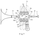
- an ideal double French horn is embodied in accordance with the present invention, and largely comprises a mouth piece 11, a front tubular member 12, an intermediate tube network 13, a rear tubular member 14 and a bell 15.
- the mouth piece 11, the front tubular member 12, the intermediate tube network 13, the rear tubular member 14 and the bell 15 are formed of alloy coated or plated with noble metal.
- all the component tubes are straight, curved and/or coiled tubes may incorporate in a practical double French horn.
- the mouth piece 11 is inserted into a front end of the front tubular member 12 which in turn is coupled with the intermediate tube network 13.
- the intermediate tube network 13 is fabricated from a front change-over valve 13a, two front straight tubular members 13b and 13c, a set of valve units 13d coupled through interconnecting tubular members 13e, another set of valve units 13f also coupled through interconnecting tubular members 13g connected with the rear end of the front tubular member 12, two rear straight tubular members 13h and 13i and a rear change-over valve 13j.
- the front change-over valve 13a has an inlet coupled with the rear end of the front tubular member 12, and the front straight tubular members 13b and 13c are coupled with two outlets of the front change-over valve 13a.
- the set of valve units 13d is coupled between the front straight tubular member 13b and the rear straight tubular member 13h, and the other set of valve units 13f is coupled between the front straight tubular member 13c and the rear straight tubular member 13i.
- the rear straight tubular members 13h and 13i are respectively coupled with two inlets of the rear change-over valve 13j, and the outlet of the rear change-over valve 13j is coupled with the rear tubular member 14.
- the front straight tubular member 13b, the set of valve units 13d, the interconnecting tubular members 13e and the rear straight tubular member 13h form a wind sub-passage 13k therein
- the front straight tubular member 13c, the set of valve units 13f, the interconnecting tubular members 13g and the rear straight tubular member 13i form another wind sub-passage 13m therein.
- the wind sub-passage 13k is assigned to the key note F
- the other wind sub-passage 13m is assigned to the key note B b
- the valve units 13d or 13f add air passages to the wind sub-passage 13k or 13m, and a player changes the pitch of a sound through manipulation on the valve units 13d or 13f.
- the rear end of the rear tubular member 14 is inserted into the front end of the bell 15, and a column of air is defined from the front tubular member 12 through either wind sub-passage 13k or 13m and the rear tubular member 14 to the bell 15.
- a column of air is defined from the front tubular member 12 through either wind sub-passage 13k or 13m and the rear tubular member 14 to the bell 15.
- FIGs. 8 and 9 of the drawings the front end portion of the rear tubular member 14 is illustrated in an enlarged scale.
- the present invention appertains to all of the connections between two component tubular members, description is made on the front end portion of the rear tubular member 14 only for avoiding repetition.
- the front end portion of the rear tubular member 14 comprises a straight tubular sub-portion 14a substantially constant in diameter and a guide sub-portion 14b merged into the straight tubular sub-portion 14a.
- the straight tubular sub-portion 14a is smaller in inner diameter than the guide sub-portion 14b, and the guide sub-portion 14b smoothly guides the outlet of the rear change-over valve 13j into the straight tubular sub-portion 14b.
- the outer diameter of the outlet of the rear change-over valve 13j is not greater than the inner diameter of the straight sub-portion 14a.
- the straight tubular sub-portion 14a and the guide sub-portion 14b serve as a tubular portion and a coupling portion, respectively.
- the guide sub-portion 14b winds from the straight tubular sub-portion 14a in the counter-clockwise direction, and projects from the outer surface of the straight sub-portion 14b.
- the winding guide sub-portion 14b forms a hollow space 14c, and the hollow space 14c is exposed to the inner space 14d in the straight tubular sub-portion 14a.
- the maximum inner diameter D3 of the rounded guide sub-portion 14b is less than the inner diameter D1 of the straight tubular sub-portion 14a, and relation between the inner diameters D1, D2 and D3 are expressed as follows.
- the guide sub-portion 14b thus shaped is larger in the modulus of section than the straight tubular sub-portion 14a, and, accordingly, reinforces the rear tubular member 14.
- the end portion 24b is expanded, and is increased in inner diameter as shown in Fig. 11A.
- a press working may be applied to the end portion by using male and female dies.
- the end portion 24b thus expanded is rounded as shown in Fig. 11B, and the rounded end portion 24b serves as the guide sub-portion 14b. Therefore, the minimum inner diameter of the rounded end portion 24b is larger than the inner diameter of the intermediate portion 24a, and a hollow space is open to the inner space of the intermediate portion 24a.
- the end portion may be also shaped through a press working.
- the tubular member 24 thus shaped is coated or plated through a plating bath, and forms a part of a wind instrument as similar to the rear tubular member 14.
- the tubular member according to the present invention is prevented from residual electrolyte confined during a plating bath without sacrifice of mechanical strength and smooth assembling.
- the outer tube of the double tube member has an end portion similarly arranged to the coupling sub-portion 14b and merged into a straight tubular portion.
- the end portion of the outer tube has a boss portion radially outwardly projecting from the outer surface of the outer tube and a leading portion merged into the boss portion and radially inwardly rounding from the boss portion.
- the straight tubular portion is smaller in inner diameter than the rounding end portion, and a hollow space defined by the end portion is open at the inner space of the straight tubular portion. A length of the hollow space is less than the inner diameter of the straight tubular portion. However, the inner diameter of the straight tubular portion may be equal to the minimum inner diameter of the end portion.
- An inner tube is smoothly inserted into the outer tube as similar to the rear tubular member 14 and the rear change-over valve 13j, and the outer tube achieves all the advantages of the rear tubular member 14.
- the present invention is applicable to any brass instrument such as a trumpet, a trombone, a tuba and a flute as well as to a wood-winds formed of metal and/or alloy.
Landscapes
- Engineering & Computer Science (AREA)
- Manufacturing & Machinery (AREA)
- Physics & Mathematics (AREA)
- Acoustics & Sound (AREA)
- Multimedia (AREA)
- Chemically Coating (AREA)
- Details Of Measuring And Other Instruments (AREA)
- Exhaust Silencers (AREA)
- Golf Clubs (AREA)
- Bending Of Plates, Rods, And Pipes (AREA)
Applications Claiming Priority (3)
| Application Number | Priority Date | Filing Date | Title |
|---|---|---|---|
| JP35512992 | 1992-12-17 | ||
| JP355129/92 | 1992-12-17 | ||
| JP4355129A JP2699790B2 (ja) | 1992-12-17 | 1992-12-17 | 管楽器の管体およびその製造方法 |
Publications (3)
| Publication Number | Publication Date |
|---|---|
| EP0602531A2 true EP0602531A2 (fr) | 1994-06-22 |
| EP0602531A3 EP0602531A3 (fr) | 1995-02-08 |
| EP0602531B1 EP0602531B1 (fr) | 1999-10-20 |
Family
ID=18442113
Family Applications (1)
| Application Number | Title | Priority Date | Filing Date |
|---|---|---|---|
| EP93119808A Expired - Lifetime EP0602531B1 (fr) | 1992-12-17 | 1993-12-08 | Instrument à vent fabriqué de pièces tubulaires métalliques à bouts arrondis vers l'intérieur |
Country Status (4)
| Country | Link |
|---|---|
| US (1) | US5503055A (fr) |
| EP (1) | EP0602531B1 (fr) |
| JP (1) | JP2699790B2 (fr) |
| DE (1) | DE69326819T2 (fr) |
Families Citing this family (4)
| Publication number | Priority date | Publication date | Assignee | Title |
|---|---|---|---|---|
| JP5811541B2 (ja) * | 2010-02-12 | 2015-11-11 | ヤマハ株式会社 | 管楽器の管体 |
| US20110219936A1 (en) * | 2010-02-12 | 2011-09-15 | Yamaha Corporation | Pipe structure of wind instrument |
| JP2011186446A (ja) * | 2010-02-12 | 2011-09-22 | Yamaha Corp | 管楽器の管体 |
| DE202018003512U1 (de) | 2018-07-27 | 2019-10-29 | Fiona Buddenbohm | Blasinstrument |
Family Cites Families (3)
| Publication number | Priority date | Publication date | Assignee | Title |
|---|---|---|---|---|
| US869619A (en) * | 1907-07-18 | 1907-10-29 | Ferdinand A Buescher | Wind musical instrument. |
| US903059A (en) * | 1907-08-02 | 1908-11-03 | Charles G Conn | Sound-reproducing bell. |
| DE2632687A1 (de) * | 1976-07-17 | 1978-01-19 | Mark S Veneklasen | Ventil-blechblasinstrument |
-
1992
- 1992-12-17 JP JP4355129A patent/JP2699790B2/ja not_active Expired - Lifetime
-
1993
- 1993-12-08 EP EP93119808A patent/EP0602531B1/fr not_active Expired - Lifetime
- 1993-12-08 DE DE69326819T patent/DE69326819T2/de not_active Expired - Lifetime
-
1995
- 1995-06-02 US US08/458,226 patent/US5503055A/en not_active Expired - Lifetime
Also Published As
| Publication number | Publication date |
|---|---|
| EP0602531A3 (fr) | 1995-02-08 |
| US5503055A (en) | 1996-04-02 |
| DE69326819T2 (de) | 2000-05-31 |
| DE69326819D1 (de) | 1999-11-25 |
| JPH06186957A (ja) | 1994-07-08 |
| JP2699790B2 (ja) | 1998-01-19 |
| EP0602531B1 (fr) | 1999-10-20 |
Similar Documents
| Publication | Publication Date | Title |
|---|---|---|
| US5782506A (en) | Flexible pipe | |
| US5408557A (en) | FC-type optical fiber cable connector's adaptor | |
| EP2409296B1 (fr) | Robinet pour instrument à vent | |
| EP0602531A2 (fr) | Instrument à vent fabriqué de pièces tubulaires métalliques à bouts arrondis vers l'intérieur | |
| KR101018980B1 (ko) | 전기 접점부 | |
| WO2022258039A1 (fr) | Instrument de musique, et parties et fabrication de celui-ci | |
| JP4472564B2 (ja) | 平衡伝送用ケーブルコネクタ | |
| US5361668A (en) | Valve for brass instrument | |
| US5285025A (en) | Loudspeaker horn | |
| EP0689184B1 (fr) | Ameliorations apportees a des instruments de musique a vent | |
| US4559859A (en) | Musical instrument | |
| US6185806B1 (en) | Method of fabricating a control assembly choosing from multiple components | |
| US20050098020A1 (en) | Brass-wind instrument valve and method | |
| US8502054B2 (en) | Saxophone neck system | |
| JP2001036301A (ja) | 円導波管 | |
| EP0580178B1 (fr) | Cor muni d'un arrangement de tubes intermédiaire ayant un diamètre interne élargi | |
| JP7313651B2 (ja) | サクソフォン | |
| KR0123467Y1 (ko) | 개선된 클라리넷의 구조 | |
| CN221102951U (zh) | 一种音响线缆的防护装置 | |
| KR100501200B1 (ko) | 바룬트랜스 | |
| JPH03105880A (ja) | 同軸コネクタ | |
| US2871748A (en) | Pitch pipes | |
| CN218729860U (zh) | 一种葫芦丝竹制音管的音管套 | |
| CN120532025A (zh) | 一种弹簧管及其组装方法、组装工装 | |
| US5012714A (en) | Brass instrument |
Legal Events
| Date | Code | Title | Description |
|---|---|---|---|
| PUAI | Public reference made under article 153(3) epc to a published international application that has entered the european phase |
Free format text: ORIGINAL CODE: 0009012 |
|
| AK | Designated contracting states |
Kind code of ref document: A2 Designated state(s): DE FR GB |
|
| PUAL | Search report despatched |
Free format text: ORIGINAL CODE: 0009013 |
|
| AK | Designated contracting states |
Kind code of ref document: A3 Designated state(s): DE FR GB |
|
| 17P | Request for examination filed |
Effective date: 19950331 |
|
| 17Q | First examination report despatched |
Effective date: 19980403 |
|
| GRAG | Despatch of communication of intention to grant |
Free format text: ORIGINAL CODE: EPIDOS AGRA |
|
| GRAG | Despatch of communication of intention to grant |
Free format text: ORIGINAL CODE: EPIDOS AGRA |
|
| GRAH | Despatch of communication of intention to grant a patent |
Free format text: ORIGINAL CODE: EPIDOS IGRA |
|
| GRAH | Despatch of communication of intention to grant a patent |
Free format text: ORIGINAL CODE: EPIDOS IGRA |
|
| GRAA | (expected) grant |
Free format text: ORIGINAL CODE: 0009210 |
|
| AK | Designated contracting states |
Kind code of ref document: B1 Designated state(s): DE FR GB |
|
| REF | Corresponds to: |
Ref document number: 69326819 Country of ref document: DE Date of ref document: 19991125 |
|
| ET | Fr: translation filed | ||
| PLBE | No opposition filed within time limit |
Free format text: ORIGINAL CODE: 0009261 |
|
| STAA | Information on the status of an ep patent application or granted ep patent |
Free format text: STATUS: NO OPPOSITION FILED WITHIN TIME LIMIT |
|
| 26N | No opposition filed | ||
| REG | Reference to a national code |
Ref country code: GB Ref legal event code: IF02 |
|
| PGFP | Annual fee paid to national office [announced via postgrant information from national office to epo] |
Ref country code: DE Payment date: 20121205 Year of fee payment: 20 |
|
| PGFP | Annual fee paid to national office [announced via postgrant information from national office to epo] |
Ref country code: GB Payment date: 20121205 Year of fee payment: 20 |
|
| PGFP | Annual fee paid to national office [announced via postgrant information from national office to epo] |
Ref country code: FR Payment date: 20130107 Year of fee payment: 20 |
|
| REG | Reference to a national code |
Ref country code: DE Ref legal event code: R071 Ref document number: 69326819 Country of ref document: DE |
|
| REG | Reference to a national code |
Ref country code: GB Ref legal event code: PE20 Expiry date: 20131207 |
|
| PG25 | Lapsed in a contracting state [announced via postgrant information from national office to epo] |
Ref country code: DE Free format text: LAPSE BECAUSE OF EXPIRATION OF PROTECTION Effective date: 20131210 Ref country code: GB Free format text: LAPSE BECAUSE OF EXPIRATION OF PROTECTION Effective date: 20131207 |