EP0602646A2 - Tintenstrahldrucker - Google Patents
Tintenstrahldrucker Download PDFInfo
- Publication number
- EP0602646A2 EP0602646A2 EP93120328A EP93120328A EP0602646A2 EP 0602646 A2 EP0602646 A2 EP 0602646A2 EP 93120328 A EP93120328 A EP 93120328A EP 93120328 A EP93120328 A EP 93120328A EP 0602646 A2 EP0602646 A2 EP 0602646A2
- Authority
- EP
- European Patent Office
- Prior art keywords
- ink
- cleaning
- pressure generating
- print head
- nozzle openings
- Prior art date
- Legal status (The legal status is an assumption and is not a legal conclusion. Google has not performed a legal analysis and makes no representation as to the accuracy of the status listed.)
- Granted
Links
- 238000004140 cleaning Methods 0.000 claims abstract description 152
- 239000004744 fabric Substances 0.000 description 8
- 229920001971 elastomer Polymers 0.000 description 4
- 239000007788 liquid Substances 0.000 description 4
- 238000000034 method Methods 0.000 description 4
- 239000007921 spray Substances 0.000 description 4
- 230000005540 biological transmission Effects 0.000 description 3
- 230000015572 biosynthetic process Effects 0.000 description 3
- 239000013013 elastic material Substances 0.000 description 3
- 230000033001 locomotion Effects 0.000 description 3
- 230000004044 response Effects 0.000 description 3
- 239000002904 solvent Substances 0.000 description 3
- 239000011248 coating agent Substances 0.000 description 2
- 238000000576 coating method Methods 0.000 description 2
- 238000010276 construction Methods 0.000 description 2
- 230000006866 deterioration Effects 0.000 description 2
- 238000010586 diagram Methods 0.000 description 2
- 230000008569 process Effects 0.000 description 2
- 238000012546 transfer Methods 0.000 description 2
- 239000011358 absorbing material Substances 0.000 description 1
- 238000013459 approach Methods 0.000 description 1
- 230000008859 change Effects 0.000 description 1
- 230000001419 dependent effect Effects 0.000 description 1
- 239000003599 detergent Substances 0.000 description 1
- 230000002542 deteriorative effect Effects 0.000 description 1
- 238000007599 discharging Methods 0.000 description 1
- 239000000839 emulsion Substances 0.000 description 1
- 239000000835 fiber Substances 0.000 description 1
- -1 for example Substances 0.000 description 1
- 230000006872 improvement Effects 0.000 description 1
- 239000000314 lubricant Substances 0.000 description 1
- 238000005259 measurement Methods 0.000 description 1
- 230000007246 mechanism Effects 0.000 description 1
- 239000003595 mist Substances 0.000 description 1
- 239000000203 mixture Substances 0.000 description 1
- 239000005445 natural material Substances 0.000 description 1
- 229920001084 poly(chloroprene) Polymers 0.000 description 1
- 230000009467 reduction Effects 0.000 description 1
- 238000007790 scraping Methods 0.000 description 1
- 229920002379 silicone rubber Polymers 0.000 description 1
- 239000004945 silicone rubber Substances 0.000 description 1
- 125000006850 spacer group Chemical group 0.000 description 1
- 235000000346 sugar Nutrition 0.000 description 1
- 150000008163 sugars Chemical class 0.000 description 1
- 229920003002 synthetic resin Polymers 0.000 description 1
- 239000000057 synthetic resin Substances 0.000 description 1
- 238000012360 testing method Methods 0.000 description 1
- XLYOFNOQVPJJNP-UHFFFAOYSA-N water Substances O XLYOFNOQVPJJNP-UHFFFAOYSA-N 0.000 description 1
Images




Classifications
-
- B—PERFORMING OPERATIONS; TRANSPORTING
- B41—PRINTING; LINING MACHINES; TYPEWRITERS; STAMPS
- B41J—TYPEWRITERS; SELECTIVE PRINTING MECHANISMS, i.e. MECHANISMS PRINTING OTHERWISE THAN FROM A FORME; CORRECTION OF TYPOGRAPHICAL ERRORS
- B41J2/00—Typewriters or selective printing mechanisms characterised by the printing or marking process for which they are designed
- B41J2/005—Typewriters or selective printing mechanisms characterised by the printing or marking process for which they are designed characterised by bringing liquid or particles selectively into contact with a printing material
- B41J2/0057—Typewriters or selective printing mechanisms characterised by the printing or marking process for which they are designed characterised by bringing liquid or particles selectively into contact with a printing material where an intermediate transfer member receives the ink before transferring it on the printing material
-
- B—PERFORMING OPERATIONS; TRANSPORTING
- B41—PRINTING; LINING MACHINES; TYPEWRITERS; STAMPS
- B41J—TYPEWRITERS; SELECTIVE PRINTING MECHANISMS, i.e. MECHANISMS PRINTING OTHERWISE THAN FROM A FORME; CORRECTION OF TYPOGRAPHICAL ERRORS
- B41J2/00—Typewriters or selective printing mechanisms characterised by the printing or marking process for which they are designed
- B41J2/005—Typewriters or selective printing mechanisms characterised by the printing or marking process for which they are designed characterised by bringing liquid or particles selectively into contact with a printing material
- B41J2/01—Ink jet
- B41J2/135—Nozzles
- B41J2/145—Arrangement thereof
- B41J2/155—Arrangement thereof for line printing
-
- B—PERFORMING OPERATIONS; TRANSPORTING
- B41—PRINTING; LINING MACHINES; TYPEWRITERS; STAMPS
- B41J—TYPEWRITERS; SELECTIVE PRINTING MECHANISMS, i.e. MECHANISMS PRINTING OTHERWISE THAN FROM A FORME; CORRECTION OF TYPOGRAPHICAL ERRORS
- B41J2/00—Typewriters or selective printing mechanisms characterised by the printing or marking process for which they are designed
- B41J2/005—Typewriters or selective printing mechanisms characterised by the printing or marking process for which they are designed characterised by bringing liquid or particles selectively into contact with a printing material
- B41J2/01—Ink jet
- B41J2/135—Nozzles
- B41J2/165—Prevention or detection of nozzle clogging, e.g. cleaning, capping or moistening for nozzles
- B41J2/16517—Cleaning of print head nozzles
- B41J2/16535—Cleaning of print head nozzles using wiping constructions
- B41J2/16544—Constructions for the positioning of wipers
-
- B—PERFORMING OPERATIONS; TRANSPORTING
- B41—PRINTING; LINING MACHINES; TYPEWRITERS; STAMPS
- B41J—TYPEWRITERS; SELECTIVE PRINTING MECHANISMS, i.e. MECHANISMS PRINTING OTHERWISE THAN FROM A FORME; CORRECTION OF TYPOGRAPHICAL ERRORS
- B41J2/00—Typewriters or selective printing mechanisms characterised by the printing or marking process for which they are designed
- B41J2/005—Typewriters or selective printing mechanisms characterised by the printing or marking process for which they are designed characterised by bringing liquid or particles selectively into contact with a printing material
- B41J2/01—Ink jet
- B41J2/135—Nozzles
- B41J2/165—Prevention or detection of nozzle clogging, e.g. cleaning, capping or moistening for nozzles
- B41J2/16517—Cleaning of print head nozzles
- B41J2/16535—Cleaning of print head nozzles using wiping constructions
- B41J2/16544—Constructions for the positioning of wipers
- B41J2/16547—Constructions for the positioning of wipers the wipers and caps or spittoons being on the same movable support
-
- B—PERFORMING OPERATIONS; TRANSPORTING
- B41—PRINTING; LINING MACHINES; TYPEWRITERS; STAMPS
- B41J—TYPEWRITERS; SELECTIVE PRINTING MECHANISMS, i.e. MECHANISMS PRINTING OTHERWISE THAN FROM A FORME; CORRECTION OF TYPOGRAPHICAL ERRORS
- B41J2/00—Typewriters or selective printing mechanisms characterised by the printing or marking process for which they are designed
- B41J2/005—Typewriters or selective printing mechanisms characterised by the printing or marking process for which they are designed characterised by bringing liquid or particles selectively into contact with a printing material
- B41J2/01—Ink jet
- B41J2/135—Nozzles
- B41J2/165—Prevention or detection of nozzle clogging, e.g. cleaning, capping or moistening for nozzles
- B41J2/16585—Prevention or detection of nozzle clogging, e.g. cleaning, capping or moistening for nozzles for paper-width or non-reciprocating print heads
Definitions
- the present invention relates to an ink jet printer.
- a print head includes a plural number of combinations each including a pressure generating chamber, a nozzle communicating with the pressure generating chamber, and a pressure generating element for varying the pressure within the pressure generating chamber.
- Print data signals drive the pressure generating elements to cause the discharge of a stream of ink droplets through the nozzles. An image is formed by the ink droplets discharged.
- This type of ink jet printer requires a smaller number of movable parts than a wire impact type printer.
- the former is superior to the latter. Accordingly, the former printer has advantages of generation of less noise and reduction of the size and cost.
- the former is inferior to the latter for the reason that since ink in liquid form is used to print images on a print paper, some types of print paper blot easily, deteriorating print quality.
- U.S. Patent No. 4,538,156 succeeds in solving the blotting problem.
- an intermediate recording medium is provided in the form of a drum or a belt. Ink droplets from the print head are received by the intermediate recording medium. After ink solvent is volatilized to some extent, the ink image formed on the recording medium is transferred to the print paper. With this arrangement, the paper does not blot, regardless of its type, and good print quality is secured.
- the printer of the above-mentioned patent must use ink of higher viscosity than a printer which projects streams of ink droplets toward the print paper directly in order to secure reliable transfer of the ink image from the intermediate recording medium to the print paper.
- Ink mist generated when ink is jetted through nozzle openings and ink spray bouncing from the intermediate recording medium collect on and adhere to the front face of the nozzle and form stiff films thereon.
- the thus-formed films can cause the jets of ink droplets to deviate from the intended course, leading to deterioration of print quality.
- the ink films must be removed at appropriate intervals of time.
- the ink jet printer of the type in which ink is directly jetted toward the print paper suffers from the same problem.
- many types of cleaning devices have been proposed to remove ink adhering to the front faces of the nozzle plates.
- these cleaning devices have been found to insufficiently remove the ink which contains compositions such as certain emulsions or sugars added thereto so as to increase the viscosity of ink and make it easy to form ink films of a type which attains improved print quality.
- an object of the present invention to provide an ink jet printer which is capable of reliably removing ink films adhering to the front face of a print head.
- the invention provides an ink jet printer employing a cleaning technique for preventing the nozzles of a print head from being clogged, particularly in an ink jet printer of the type which uses high viscosity ink which hardens easily so as to improve print quality.
- an ink jet printer comprising: a print head including a plural number of pressure generating chambers communicating with nozzle openings and pressure generating elements each for varying a pressure to cause the ejection of a stream of ink droplets from the pressure chamber through the nozzle openings, the pressure generating chambers and the pressure generating elements being arrayed in the width direction of a print paper; head drive means for selectively outputting a first signal to cause a stream of ink droplets at a speed suitable for printing and a second signal to cause ink to ooze through each nozzle opening; cleaning means usually positioned in a nonprinting region, but movable in the longitudinal direction of the print head and with respect to a nozzle plate; drive means for moving the cleaning means in the longitudinal direction of the print head; and control means for causing the head drive means to output the second signal in connection with the position of the cleaning means.
- ink is discharged to such an measure as to moisten the front face of the nozzle plate before the cleaning means is operated. Accordingly, the ink hardened with time on the nozzle plate can easily be dissolved by the ink solvent.
- Fig. 1 is a perspective view showing an ink jet printer constructed in accordance with a first preferred embodiment of the present invention.
- reference numeral 1 designates a print head for emitting a jet of ink droplets toward an intermediate recording medium (to be described later).
- the recording or print head 1 which has an elongated form, includes an array of nozzle openings extending in the width direction of a print paper so as to form a plural number of dots arrayed in a similar fashion by one time emission of ink.
- reference numeral 11 designates a nozzle plate.
- About 2,000 nozzle openings 12 are arrayed linearly or in a zig-zag fashion in the nozzle plate 11.
- the array of the nozzle opening 12 is long enough to cover the width of a print paper of the maximum size.
- a plural number (e.g., 400) of nozzle openings are arrayed at the pitch of a plural number ( e.g., five) of dots in the row direction.
- the print head 1 is shifted one dot every turn of an intermediate recording medium 3 so as to complete the image formation of one page when it is turned five times.
- the print head 1 may be constructed shorter than the print paper width, having, for example, 100 nozzle openings 12 arrayed at a pitch of five dots. In this case, five cycle motions of the print head 1 completes the formation of an image of length equal to the width of the print head 1. Then, the print head 1 is moved a distance of the entire length of the head, and the above steps are repeated to form an image of the print paper width.
- a vibrating plate 15 having a thick part facing each pressure generating chamber 14 is supported by an ink supply member 16.
- a piezoelectric vibrator 17 is constructed such that a piezoelectric vibrating member is sandwiched by electrodes so that it vibrates in a longitudinal vibration mode by a drive voltage as low as possible.
- the same number of piezoelectric vibrators 17 as that of the nozzle openings 12 are fixed to a base 18 in a state that the forward ends of the piezoelectric vibrators 17 are in contact with the vibrating plate 15.
- Each piezoelectric vibrator 17 is operable in two modes.
- the piezoelectric vibrator 17 when receiving a drive signal, the piezoelectric vibrator 17 produces energy sufficient to cause ink droplets to strike against the surface of the intermediate recording medium 3 at the speed of 6 m/s or more. In the second mode, it produces such a small energy as to cause ink to only ooze through the nozzle opening 12.
- the print head 1 In order to smoothly supply ink to the entire elongated print head 1, the print head 1 is connected to an ink tank 6 by way of ink flow paths 4 and 5, such as tubes. A pump 8 is inserted in the ink flow path 5. A valve 7 is inserted in the ink flow path 4. Through the ink flow circuit, ink is supplied to the print head 1 in a circulating manner. In the print head 1, ink is supplied to the pressure generating chambers 14 through support members 19. Because of the elongated shape of the print head 1, it is mounted on a support member 9. A drive device 20 is provided at one end of the support member 9, while a spring 21 is connected to the other end of the support member 9.
- the drive device 20 When the drive device 20 is turned in the direction of an arrow C, it cooperates with spring 21 to move the support member 9 or the print head 1 a small distance reciprocatively in the directions of arrows G and F (paper width direction). In this way, the print head 1 can emit ink at an appropriate position.
- the intermediate recording medium 3 which receives ink droplets from the print head 1, is constructed with a drum of such a length as to be able to receive ink droplets from the print head 1.
- a layer of silicone rubber is formed on the surface of the drum so that an ink image formed thereon can easily be transferred to a recording paper 26.
- the intermediate recording medium 3 is coupled with a motor 24 through a power transmission 22 and 23.
- the intermediate recording medium 3 is rotated in the direction of an arrow H in synchronism with the emission of ink droplets by a drive system including the motor 24 and the power transmission 22 and 23.
- the pressure roller 25 is supported by bearings such that it may come in contact with and be moved away from the intermediate recording medium 3.
- paired springs 27 and 27 push the pressure roller 25 in the direction of an arrow I so that the pressure roller 25 presses the recording paper 26 against the intermediate recording medium 3.
- a cleaning device 30 is mounted on a carriage 34.
- the carriage 34 is supported by a pair of guides 31, and coupled with a motor 33 by a timing belt 32.
- the carriage 34 carrying the cleaning device 30 stays outside a printing region, and in a cleaning mode, it is movable over the entire length of the print head 1.
- reference numeral 40 designates a first cleaning member whose function is to rub the front face of the nozzle plate 11.
- a roller 43 made of elastic material, for example, rubber, is formed on a rotary shaft 42 that is connected through a power transmission means 41 to a drive source (not shown).
- a layer of unwoven cloth 45 which is made of fine fibers and hence free of pieces of thread, is layered on the surface of the roller 43.
- the rotary shaft 42 of the roller 43 is rotatably supported by a base member 44.
- Reference numeral 46 designates a second cleaning member whose function is to wipe the front face of the nozzle plate 11.
- the second cleaning member 46 which is to be in resilient contact with the front face of the print head 1, is formed with a plate of chloroprene rubber approximately 1 mm thick.
- the second cleaning member 46 is located adjacent the first cleaning member 40 as viewed in the carriage moving direction.
- An ink guide member 48 is provided for guiding the ink wiped off by the second cleaning member 46 to the first cleaning member 40.
- the ink guide member 48 is slantingly disposed such that one end of the ink guide member 48 is located under the lower end of the second cleaning member 46, while the other end thereof is disposed at a location below the lower end of the second cleaning member 46 in a state such that it is brought into contact with the surface of the first cleaning member 40.
- reference numeral 50 designates a control unit for controlling the cleaning operation of the print head 1.
- the control unit 50 controls both a first drive circuit 51 and a second drive circuit 52 for moving the cleaning device 30.
- the control unit 50 is composed of a signal discriminator 60, a cleaning device control unit 61, a position detector 62, an ink-feed signal generator 63, and a timer 64.
- the signal discriminator 60 discriminates a cleaning instruction contained in a signal received from an external device.
- the cleaning device control unit 61 controls the rotation and the positioning of the cleaning device 30.
- the position detector 62 detects the position of the cleaning unit 30, for example, with a counter for counting the number of drive pulses supplied to the motor 33.
- the ink-feed signal generator 63 produces a signal for causing the print head 1 to discharge ink with an ink drive energy of such magnitude as to moisten the print head 1, e.g., an energy approximately 1/10 to 1/2 as large as the drive energy for printing.
- the timer 64 sets the time interval of the cleaning operation.
- the motor 33 in response to a print instruction from an external device, the motor 33 is operated to retract the cleaning device 30 to a nonprinting region, while at the same time the motor 24 is operated to turn the intermediate recording medium 3 in the direction H.
- the first drive circuit 51 produces a drive signal which drives the piezoelectric vibrator 17 designated by print data to cause the discharge of the streams of ink droplets for printing.
- the print head 1 discharges jets of ink droplets toward the intermediate recording medium 3, thereby forming an image of ink as the mirror image of an image to be printed.
- a signal is supplied to the drive unit 20.
- the print head 1 is moved a predetermined distance in the paper width direction, for example, the direction F.
- an image of ink is formed at the position designated by the print data as previously stated.
- a recording paper 26 is supplied from a paper cassette (not shown) to a transfer region, i.e., a region under the pressure roller 25. Then, the pressure roller 25 presses the recording paper 26 against the intermediate recording medium 3 in cooperation with the springs 27. Under this condition, the recording paper 26 is forwarded in synchronism with the movement of the half-dried ink image on the surface of the intermediate recording medium 3. As a result, the ink image is transferred to the recording paper 26 with the assistance of its increased viscosity.
- ink spray is attached to the surface of the nozzle plate 11 of the print head 1 and dried.
- the ink spray attached and dried can possibly change the speed and direction of the streams of ink droplets. Accordingly, the print quality gradually deteriorates.
- an operator pushes a button for issuing a cleaning instruction or the timer 64 produces a cleaning instruction signal when a count reaches a preset value.
- the signal discriminator 60 discriminates the cleaning instruction, and outputs a signal to the control unit 61.
- the control unit 61 outputs a signal to the second drive circuit 52, which then causes the motor 33 to turn. With the turning of the motor, the cleaning device 30 is moved from the nonprinting region to the printing region. At the same time, the second drive unit drives the first cleaning member 40 to turn.
- the output signal of the signal discriminator 60 is also input to the ink-feed signal generator 63.
- the ink-feed signal generator 63 receives a signal indicative of the present position of the cleaning device 30 from the position detector 62, and selects the nozzle opening 12 confronted by the first cleaning member 40 and several nozzle openings 12 preceding and subsequent to the former opening. Then, the ink-feed signal generator 63 drives the first drive circuit 51 to output a drive signal to the piezoelectric vibrators 17 corresponding to the selected nozzle openings 12 through which ink is to be forcibly discharged.
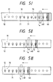
- Dried ink spots 70 located forward of the first cleaning member 40 are moistened and softened by ink droplets 71 discharged from the nozzle openings 12.
- the first cleaning member 40 rubs the moistened ink spots 70 off the front face of the nozzle plate 11 using as a lubricant ink droplets 71 exuding through the nozzle openings 12 (Fig. 5(I)).
- the ink thus rubbed off is wiped away by the layer of unwoven cloth 45 of the first cleaning member 40 (Fig. 5(II)).
- the nozzle openings 12 located forward of the second cleaning member 46 also discharge ink. Accordingly, the region where rubbing has been completed is further moistened by the ink.
- the second cleaning member 46 now passes the rubbing-off completed region to wipe away ink 72 left after the cleaning by the first cleaning member 40 and the ink discharged from the nozzle openings 12 (Fig. 5(III)). In this way, ink left after the cleaning by the first cleaning member 40 and ink residue attached again are wiped away by the second cleaning member 46.
- the ink is then absorbed by the unwoven cloth 45 of the first cleaning member 40, and used to moisten the front face of the nozzle plate 11.
- the use of the ink thus collected eliminates an additional supply of fresh ink for cleaning.
- the control unit 61 detects this and rotates the motor 33 in the reverse direction, and move the cleaning device 30 to the nonprinting region. This cleaning operation is repeated until the print head 1 regains the normal ink discharge function.
- the first cleaning member 40 is rotated at a reduced speed.
- the ink is continuously discharged from the nozzle openings 12 located in the cleaning region. If required, it may be discharged intermittently.
- a cleaning device including a first cleaning member and a second cleaning member was used.
- the first cleaning member a layer of unwoven cloth covered the surface of a rubber roller 16 mm in diameter.
- the first cleaning member was rotated at a speed of 120 rpm.
- the second cleaning member was a rubber plate 1 mm thick.
- the front face of a nozzle plate of a print head was coated with a predetermined amount of ink. Cleaning operations were carried out while exuding ink through the nozzle openings. The same operations were also carried out while not flowing ink therethrough, that is, in the conventional manner.
- the number of cleaning operations repeated until the normal print function of the print head was restored was measured for different times elapsing after the nozzle plate was coated with ink and left to stand. The results of these measurements were as shown in Fig. 6.
- the first and second cleaning members are constantly brought into contact with the print head.
- the cleaning members may be selectively brought into contact with the print head.
- a drive unit such as a solenoid, is coupled with the support for the cleaning members so that it selectively moves the first and second cleaning members toward and from the face of the print head.
- the cleaning device operates selectively in a wiping mode and a rubbing mode, thereby securing further complete cleaning.
- Fig. 7 is a perspective view showing another cleaning device according to the present invention.
- reference numeral 80 designates a first cleaning member
- numeral 81 represents a second cleaning member.
- the carriage 83 is guided by a guide member 31, and 31 by means of a rack-pinion mechanism, in the direction in which the nozzle openings are arrayed.
- a pinion (not shown) in the carriage 83 is in mesh with a rack 89 disposed also in the direction of the nozzle opening array.
- the member body proper is fastened to a drive shaft 90 engaging an eccentric cam 88, which is coupled with a rotary drive unit 87.
- the member body proper is mounted on a base 93, which is constantly pressed downward by springs 92, which are inserted between the other end of the member body proper and a frame 91.
- a pair of cleaning members the first and second cleaning members, are mounted on the carriage 83.
- two pairs of first and second cleaning members 95 and 96, and 97 and 98 are disposed side by side in their direction of movement. The use of two pairs of cleaning members provides further improved cleaning performances.
- Figs. 10(a) and 10(b) are sectional views showing another type of the first cleaning member of the cleaning device with a rubbing function, which can be used in the ink jet printer of the invention.
- a main body case 100 extends along the array of the nozzle openings 12 of the print head 1.
- the body case 100 has an elongated opening in the side thereof facing the arrayed nozzle openings 12. Through the elongated opening a cleaning unit 101 (to be described later) is exposed to the outside.
- a cavity 102 for receiving ink residue is formed in the bottom of the main body case.
- the cleaning unit designated by reference numeral 103, is constructed such that, as shown in Fig. 11(a), a layer 106 formed of an unwoven cloth, for example, is provided on the surface of a roller 105 made of elastic material, and the roller 105 is fastened to a rotary shaft 104, which is driven by an external device.
- a blade 107 resiliently contacts the surface of the cleaning unit 103 so that ink and ink residue adhering to the surface of the cleaning unit 103 are scraped off the surface.
- the cleaning unit 101 is rotated by means of a drive unit (not shown) while exuding ink droplets through the nozzle openings 12.
- the area around the nozzle openings is rubbed with the unwoven cloth layer 106, thereby scraping the hardened ink from the area.
- the ink residue scrapped off through the process of cleaning drops into the cavity 102, and is thus confined within the main body case 100.
- the cleaning unit 103 may use a brush as shown in Fig. 11(b).
- the brush long and circular in cross section, includes resilient bristles 111 fastened to a rotary shaft 110.
- the resilient bristles 111 are made of synthetic resin or a natural material which will not damage the nozzle plate 11.
- Cleaning units constructed as shown in Figs. 11(c) and 11(d) are suitable for the cleaning unit of the type in which the shaft is reciprocatively turned.
- a rubbing member 114 is mounted on a base plate 113, which is reciprocatively turned by an external device.
- the rubbing member 114 is constructed such that the surface of a long resilient member fixed to the base plate 113 is covered with unwoven cloth.
- resilient bristles 115 are planted in the base plate 113.
- ink droplets for cleaning are supplied as in the ink discharging operation in the print mode.
- the ink jet printer has the ink flow control circuit 120, which controls the operation of the pump 8, for supplying ink from the ink tank 6 to the print head 1 at a slightly higher speed, and/or the operation of the valve 7.
- the ink pressure within the print head 1 is increased by a signal from a control unit 121 similar to that of the previous case. Under this condition, the ink is discharged through all of the nozzle openings 12 immediately before the cleaning operation starts, and then the cleaning operation by the second drive circuit 52 starts.
- ink is used for moistening the nozzle plate 11.
- the ink may be replaced with a liquid which will not harden the ink when it is applied through the nozzle opening 12 to the print head 1.
- An example of such a liquid is ink solvent.
- the cleaning operation by the first and second cleaning members is carried out after the nozzle plate 11 is coated with such a liquid using a suitable coating device.
- ink droplets discharged from the print head are received by the intermediate recording medium, and then the image formed by the ink droplets is transferred from the intermediate recording medium to a print paper. It is evident though that the present invention is applicable for the ink jet printer of the type in which an image is directly formed on the print paper by ink droplets discharged from the print head.
- the ink jet printer includes a print head including a plural number of pressure generating chambers communicating with nozzle openings and pressure generating elements each for varying a pressure to within a corresponding pressure generating chamber to jet from the respective nozzle opening a stream of ink droplets, the pressure generating chambers and the pressure generating elements being arrayed in the width direction of a print paper; head drive means for selectively outputting a first signal to cause a stream of ink droplets at a speed suitable for print and a second signal to cause ink to ooze through each nozzle opening; cleaning means being usually positioned in a nonprinting region, but movable in the longitudinal direction of the print head and with respect to a nozzle plate; drive means for moving the cleaning means in the longitudinal direction of the print head; and a control unit for causing the head drive means to output the second signal in connection with a position of the cleaning means.
Landscapes
- Ink Jet (AREA)
Applications Claiming Priority (8)
| Application Number | Priority Date | Filing Date | Title |
|---|---|---|---|
| JP33638392 | 1992-12-16 | ||
| JP336383/92 | 1992-12-16 | ||
| JP33638292 | 1992-12-16 | ||
| JP336382/92 | 1992-12-16 | ||
| JP10558093 | 1993-05-06 | ||
| JP105580/93 | 1993-05-06 | ||
| JP314134/93 | 1993-11-19 | ||
| JP31413493A JP3535885B2 (ja) | 1992-12-16 | 1993-11-19 | インクジェット式記録装置 |
Publications (3)
| Publication Number | Publication Date |
|---|---|
| EP0602646A2 true EP0602646A2 (de) | 1994-06-22 |
| EP0602646A3 EP0602646A3 (de) | 1994-07-27 |
| EP0602646B1 EP0602646B1 (de) | 1997-10-15 |
Family
ID=27469340
Family Applications (1)
| Application Number | Title | Priority Date | Filing Date |
|---|---|---|---|
| EP93120328A Expired - Lifetime EP0602646B1 (de) | 1992-12-16 | 1993-12-16 | Tintenstrahldrucker |
Country Status (4)
| Country | Link |
|---|---|
| US (2) | US5557306A (de) |
| EP (1) | EP0602646B1 (de) |
| JP (1) | JP3535885B2 (de) |
| DE (1) | DE69314608T2 (de) |
Cited By (11)
| Publication number | Priority date | Publication date | Assignee | Title |
|---|---|---|---|---|
| US5614930A (en) * | 1994-03-25 | 1997-03-25 | Hewlett-Packard Company | Orthogonal rotary wiping system for inkjet printheads |
| FR2741296A1 (fr) * | 1995-11-17 | 1997-05-23 | Chapel Reprographie | Dispositif rapide d'impression jet d'encre |
| US5706038A (en) * | 1994-10-28 | 1998-01-06 | Hewlett-Packard Company | Wet wiping system for inkjet printheads |
| US6145958A (en) * | 1997-11-05 | 2000-11-14 | Hewlett-Packard Company | Recycling ink solvent system for inkjet printheads |
| US6860583B2 (en) | 2002-12-27 | 2005-03-01 | Hewlett-Packard Development Company, L.P. | Waste ink absorption system and method |
| EP1520699A3 (de) * | 1998-12-16 | 2005-04-20 | Silverbrook Research Pty. Limited | Digitales Drucksystem zum Druck auf beiden Seiten des Blattes |
| EP1658980A1 (de) * | 2004-11-19 | 2006-05-24 | Samsung Electronics Co., Ltd. | Tintenstrahldrucker |
| US7380903B2 (en) | 2003-09-10 | 2008-06-03 | Fujifilm Corporation | Inkjet recording apparatus, and ink discharge surface cleaning method and device |
| CN100423939C (zh) * | 1998-12-16 | 2008-10-08 | 西尔弗布鲁克研究有限公司 | 双面喷墨打印系统 |
| US7484840B2 (en) | 1998-12-16 | 2009-02-03 | Silverbrook Research Pty Ltd | Transfer roller assembly for a compact printer |
| US7566123B2 (en) | 1998-12-16 | 2009-07-28 | Silverbrook Research Pty Ltd | Double-sided printer having opposed print engines |
Families Citing this family (77)
| Publication number | Priority date | Publication date | Assignee | Title |
|---|---|---|---|---|
| JP3535885B2 (ja) * | 1992-12-16 | 2004-06-07 | セイコーエプソン株式会社 | インクジェット式記録装置 |
| IES65774B2 (en) * | 1994-03-31 | 1995-11-15 | Joseph Frederick Fritsch | A cleaning device |
| EP0676289B1 (de) * | 1994-04-08 | 1999-02-10 | Hewlett-Packard Company | Feuchtwischer für einen Tintenstrahldruckkopf |
| US5847674A (en) * | 1996-05-02 | 1998-12-08 | Moore Business Forms, Inc. | Apparatus and methods for maintaining optimum print quality in an ink jet printer after periods of inactivity |
| US6102509A (en) * | 1996-05-30 | 2000-08-15 | Hewlett-Packard Company | Adaptive method for handling inkjet printing media |
| US5838338A (en) * | 1996-05-30 | 1998-11-17 | Hewlett-Packard Company | Adaptive media handling system for printing mechanisms |
| US5949448A (en) * | 1997-01-31 | 1999-09-07 | Hewlett-Packard Company | Fiber cleaning system for inkjet printhead wipers |
| US6532025B1 (en) | 1997-11-14 | 2003-03-11 | Canon Kabushiki Kaisha | Ink jet recording apparatus provided with an improved cleaning mechanism |
| US6145953A (en) * | 1998-01-15 | 2000-11-14 | Hewlett-Packard Company | Ink solvent application system for inkjet printheads |
| JP4020126B2 (ja) * | 1998-03-24 | 2007-12-12 | コニカミノルタホールディングス株式会社 | 液体吐出装置 |
| JP3924979B2 (ja) * | 1998-03-24 | 2007-06-06 | コニカミノルタホールディングス株式会社 | 液体吐出装置 |
| US6513434B1 (en) * | 1999-05-17 | 2003-02-04 | Fuji Photo Film Co., Ltd. | On-press recording type lithographic printing method and apparatus |
| JP4536858B2 (ja) * | 1999-07-23 | 2010-09-01 | 武藤工業株式会社 | インクジェットプリンタ |
| JP4945843B2 (ja) | 2001-02-21 | 2012-06-06 | ソニー株式会社 | インクジェットヘッド及びインクジェットプリンタ |
| US6491366B1 (en) * | 2001-08-20 | 2002-12-10 | Hewlett-Packard Company | Ink drop detector waste ink removal system |
| US6659586B2 (en) * | 2001-09-05 | 2003-12-09 | Hewlett-Packard Development Company, L.P. | System and method for servicing non-scanning printhead |
| US6660103B1 (en) | 2002-03-28 | 2003-12-09 | Vutek, Inc. | Cleaning process for ink jet printheads |
| EP1375156B1 (de) | 2002-06-28 | 2005-08-31 | Agfa-Gevaert | Verfahren zum Reinigen der Düsenplatte |
| JP3750808B2 (ja) * | 2002-07-26 | 2006-03-01 | ブラザー工業株式会社 | インクジェットプリンタ |
| US6866361B2 (en) * | 2002-10-02 | 2005-03-15 | Brother Kogyo Kabushiki Kaisha | Ink-jet recording apparatus and maintenance method of ink-jet head included in ink-jet recording apparatus |
| US20040160472A1 (en) * | 2003-02-14 | 2004-08-19 | Najeeb Khalid | Retractable high-speed ink jet print head and maintenance station |
| US7083253B2 (en) * | 2003-03-25 | 2006-08-01 | Toshiba Tec Kabushiki Kaisha | Ink jet recording apparatus having cleaning means for the cleaning of the nozzle surface of an ink jet head |
| US20040257396A1 (en) * | 2003-06-19 | 2004-12-23 | Toshiba Tec Kabushiki Kaisha | Ink jet head cleaning apparatus and ink jet recording apparatus |
| JP3966242B2 (ja) | 2003-06-30 | 2007-08-29 | ブラザー工業株式会社 | インクジェットプリンタ |
| JP2005080378A (ja) * | 2003-08-29 | 2005-03-24 | Konica Minolta Business Technologies Inc | 駆動装置、画像形成装置 |
| JP4035096B2 (ja) * | 2003-08-29 | 2008-01-16 | 松下電器産業株式会社 | インクジェット式記録装置 |
| JP3918117B2 (ja) * | 2003-09-10 | 2007-05-23 | 富士フイルム株式会社 | インクジェット記録装置及びインク吐出面清掃方法 |
| US7044580B2 (en) | 2003-11-18 | 2006-05-16 | Toshiba Tec Kabushiki Kaisha | Ink jet recording head maintenance apparatus and ink jet recording apparatus |
| US7128410B2 (en) * | 2004-03-17 | 2006-10-31 | Videojet Technologies Inc. | Ink jet print head cleaning system |
| US7150512B2 (en) * | 2004-03-17 | 2006-12-19 | Videojet Technologies Inc. | Cleaning system for a continuous ink jet printer |
| KR100828355B1 (ko) * | 2004-05-25 | 2008-05-08 | 삼성전자주식회사 | 잉크젯 프린터 |
| JP2006088617A (ja) * | 2004-09-27 | 2006-04-06 | Brother Ind Ltd | インクジェット記録装置 |
| KR20060059346A (ko) * | 2004-11-27 | 2006-06-02 | 삼성전자주식회사 | 잉크젯 프린터 |
| JP2006212863A (ja) * | 2005-02-02 | 2006-08-17 | Fuji Xerox Co Ltd | インクジェット記録装置、及びインクジェット記録ヘッドのノズル面の清掃方法 |
| JP2006218747A (ja) * | 2005-02-10 | 2006-08-24 | Fuji Xerox Co Ltd | インクジェット記録装置及びワイピング方法 |
| JP4565637B2 (ja) * | 2005-03-04 | 2010-10-20 | キヤノン株式会社 | インクジェット記録装置 |
| JP2006327123A (ja) * | 2005-05-30 | 2006-12-07 | Canon Finetech Inc | フェイス面清掃方法及びインクジェット方式画像形成装置 |
| US7648219B2 (en) * | 2005-09-21 | 2010-01-19 | Brother Kogyo Kabushiki Kaisha | Liquid-droplet jetting apparatus having a movable body for detecting and purging abnormal nozzles |
| US7575297B2 (en) * | 2005-10-11 | 2009-08-18 | Silverbrook Research Pty Ltd | Method of unblocking nozzles in a printhead |
| US7695098B2 (en) * | 2005-10-11 | 2010-04-13 | Silverbrook Research Pty Ltd | Printhead maintenance system comprising disposable sheet feed |
| US7686419B2 (en) * | 2005-10-11 | 2010-03-30 | Silverbrook Research Pty Ltd | Method of maintaining a printhead using a roller action |
| US7467846B2 (en) * | 2005-10-11 | 2008-12-23 | Silverbrook Research Pty Ltd | Printhead maintenance system comprising face flooding system and ink transport assembly |
| US7695093B2 (en) * | 2005-10-11 | 2010-04-13 | Silverbrook Research Pty Ltd | Method of removing flooded ink from a printhead using a disposable sheet |
| US7753472B2 (en) * | 2005-10-11 | 2010-07-13 | Silverbrook Research Pty Ltd | Printhead maintenance station having rotational pad engagement |
| US7648222B2 (en) * | 2005-10-11 | 2010-01-19 | Silverbrook Research Pty Ltd | Printhead maintenance station comprising maintenance roller and ink removal system |
| US7370936B2 (en) * | 2005-10-11 | 2008-05-13 | Silverbrook Research Pty Ltd | Method of maintaining a printhead using film transport of ink |
| US7506952B2 (en) * | 2005-10-11 | 2009-03-24 | Silverbrook Research Pty Ltd | Method of removing particulates from a printhead using film transfer |
| US7695097B2 (en) * | 2005-10-11 | 2010-04-13 | Silverbrook Research Pty Ltd | Printhead maintenance station having roller pad |
| US7438381B2 (en) * | 2005-10-11 | 2008-10-21 | Silverbrook Research Pty Ltd | Method of removing flooded ink from a printhead |
| US7441863B2 (en) * | 2005-10-11 | 2008-10-28 | Silverbrook Research Pty Ltd. | Method of sealing nozzles on a printhead |
| JP4197004B2 (ja) * | 2006-05-11 | 2008-12-17 | ブラザー工業株式会社 | インクジェット記録装置 |
| JP4175391B2 (ja) * | 2006-06-12 | 2008-11-05 | ブラザー工業株式会社 | インクジェット記録装置 |
| JP4895723B2 (ja) | 2006-08-23 | 2012-03-14 | 富士フイルム株式会社 | 液体吐出装置および液体吐出面の清掃方法 |
| JP4349411B2 (ja) * | 2006-12-05 | 2009-10-21 | ブラザー工業株式会社 | 液体吐出装置 |
| JP5269329B2 (ja) * | 2007-03-09 | 2013-08-21 | 富士フイルム株式会社 | 液体吐出装置及び液体吐出面メンテナンス方法 |
| JP2008279644A (ja) * | 2007-05-10 | 2008-11-20 | Ricoh Co Ltd | 維持回復方法、維持回復機構及び画像形成装置 |
| JP4502018B2 (ja) * | 2008-01-28 | 2010-07-14 | 富士ゼロックス株式会社 | 液滴吐出装置 |
| JP4613978B2 (ja) | 2008-05-13 | 2011-01-19 | 富士ゼロックス株式会社 | 液滴吐出装置 |
| JP4784657B2 (ja) * | 2009-02-04 | 2011-10-05 | ブラザー工業株式会社 | 記録装置 |
| JP2010208147A (ja) | 2009-03-10 | 2010-09-24 | Ricoh Co Ltd | ヘッドクリーニング装置、画像形成装置及びヘッドクリーニング方法 |
| JP5343806B2 (ja) * | 2009-10-07 | 2013-11-13 | セイコーエプソン株式会社 | 流体噴射装置 |
| JP5328615B2 (ja) * | 2009-11-10 | 2013-10-30 | キヤノン株式会社 | インクジェット記録装置 |
| JP2011131193A (ja) * | 2009-12-25 | 2011-07-07 | Seiko Epson Corp | 流体噴射装置 |
| EP2371551B1 (de) * | 2010-03-29 | 2018-10-17 | Brother Kogyo Kabushiki Kaisha | Flüssigkeitsausstoßvorrichtung |
| EP2655071A1 (de) * | 2010-12-21 | 2013-10-30 | OCE-Technologies B.V. | Verfahren zur bestimmung der leistung einer wartungseinheit |
| JP5500083B2 (ja) * | 2011-01-06 | 2014-05-21 | ブラザー工業株式会社 | 液体吐出装置、制御装置、及び、プログラム |
| US8382239B2 (en) | 2011-01-31 | 2013-02-26 | Xerox Corporation | Apparatus for removing ink from surfaces of components in a printer |
| ES2453271T3 (es) | 2011-06-29 | 2014-04-07 | Agfa Graphics N.V. | Sistema y método para limpiar una placa de boquillas |
| US8684506B2 (en) | 2011-08-29 | 2014-04-01 | Xerox Corporation | Apparatus and method for collecting and expelling phase change ink in a printer |
| US8529015B2 (en) | 2012-02-02 | 2013-09-10 | Xerox Corporation | Apparatus and method for removal of ink from an exterior of a printhead |
| JP2013212652A (ja) * | 2012-04-03 | 2013-10-17 | Toshiba Tec Corp | インクジェット記録装置 |
| US8727485B2 (en) | 2012-05-14 | 2014-05-20 | Xerox Corporation | Three position printhead wiper assembly |
| JP5892099B2 (ja) * | 2013-03-27 | 2016-03-23 | ブラザー工業株式会社 | 液体吐出装置 |
| JP6340924B2 (ja) * | 2013-09-30 | 2018-06-13 | 京セラドキュメントソリューションズ株式会社 | 記録ヘッドの回復システム及びそれを備えたインクジェット記録装置、並びに記録ヘッドの回復方法 |
| US9358802B2 (en) | 2014-03-28 | 2016-06-07 | Seiko Epson Corporation | Liquid ejecting head, liquid ejecting apparatus, flow passage member, and method of controlling liquid ejecting head |
| JP6471547B2 (ja) * | 2015-03-13 | 2019-02-20 | セイコーエプソン株式会社 | 液体噴射装置 |
| JP2016221777A (ja) | 2015-05-28 | 2016-12-28 | セイコーエプソン株式会社 | 液体噴射ヘッドユニット、液体噴射装置及びワイピング方法 |
Family Cites Families (23)
| Publication number | Priority date | Publication date | Assignee | Title |
|---|---|---|---|---|
| JPS5448551A (en) * | 1977-09-26 | 1979-04-17 | Ricoh Co Ltd | Ink jet driving circuit |
| DE2754630C3 (de) * | 1977-12-08 | 1981-02-19 | Olympia Werke Ag, 2940 Wilhelmshaven | Verfahren und Medium zum Reinigen der Düsenfläche an einem Tintenschreibkopf |
| JPS5734969A (en) * | 1980-08-11 | 1982-02-25 | Matsushita Electric Ind Co Ltd | Ink jet recorder |
| JPS5761574A (en) * | 1980-09-30 | 1982-04-14 | Sharp Corp | Ink jet recording device |
| US4340897A (en) * | 1981-07-29 | 1982-07-20 | Pitney Bowes Inc. | Cleaning device for writing heads used in ink jet recorders and printers |
| US4369456A (en) * | 1981-08-26 | 1983-01-18 | Pitney Bowes Inc. | Cleaning device for writing heads used in ink jet recorders and printers |
| JPS5914963A (ja) * | 1982-07-15 | 1984-01-25 | Seiko Epson Corp | インクジエツトプリンタのノズルキヤツプ |
| JPS5983664A (ja) * | 1982-11-02 | 1984-05-15 | Matsushita Electric Ind Co Ltd | インクジエツトヘツドクリ−ニング装置 |
| US4538156A (en) * | 1983-05-23 | 1985-08-27 | At&T Teletype Corporation | Ink jet printer |
| JP2626805B2 (ja) * | 1987-10-30 | 1997-07-02 | キヤノン株式会社 | インクジェット記録装置 |
| JP2801196B2 (ja) * | 1987-11-20 | 1998-09-21 | キヤノン株式会社 | 液体噴射装置 |
| US5040000A (en) * | 1988-05-12 | 1991-08-13 | Canon Kabushiki Kaisha | Ink jet recording apparatus having a space saving ink recovery system |
| JPH02179757A (ja) * | 1988-12-30 | 1990-07-12 | Canon Inc | 画像記録装置 |
| JP2798438B2 (ja) * | 1989-09-13 | 1998-09-17 | 富士通株式会社 | インクジェットヘッドのクリーニング方法 |
| JPH03138157A (ja) * | 1989-10-24 | 1991-06-12 | Fuji Xerox Co Ltd | インクジェット装置におけるメンテナンス方法および装置 |
| JP2774639B2 (ja) * | 1990-02-13 | 1998-07-09 | キヤノン株式会社 | インクジェット記録装置 |
| JP2750769B2 (ja) * | 1990-03-08 | 1998-05-13 | キヤノン株式会社 | インクジェット記録装置 |
| JP2979192B2 (ja) * | 1990-05-09 | 1999-11-15 | 株式会社ホクシンクロス | 壁張地の製法 |
| US5051761A (en) * | 1990-05-09 | 1991-09-24 | Xerox Corporation | Ink jet printer having a paper handling and maintenance station assembly |
| US5103244A (en) * | 1990-07-05 | 1992-04-07 | Hewlett-Packard Company | Method and apparatus for cleaning ink-jet printheads |
| JPH0480042A (ja) * | 1990-07-24 | 1992-03-13 | Nec Corp | インクジェットヘッドのクリーニング機構 |
| US5250962A (en) * | 1991-10-16 | 1993-10-05 | Xerox Corporation | Movable ink jet priming station |
| JP3535885B2 (ja) * | 1992-12-16 | 2004-06-07 | セイコーエプソン株式会社 | インクジェット式記録装置 |
-
1993
- 1993-11-19 JP JP31413493A patent/JP3535885B2/ja not_active Expired - Lifetime
- 1993-12-15 US US08/167,073 patent/US5557306A/en not_active Expired - Fee Related
- 1993-12-16 EP EP93120328A patent/EP0602646B1/de not_active Expired - Lifetime
- 1993-12-16 DE DE69314608T patent/DE69314608T2/de not_active Expired - Lifetime
-
1996
- 1996-03-04 US US08/610,285 patent/US6158839A/en not_active Expired - Lifetime
Cited By (17)
| Publication number | Priority date | Publication date | Assignee | Title |
|---|---|---|---|---|
| US5614930A (en) * | 1994-03-25 | 1997-03-25 | Hewlett-Packard Company | Orthogonal rotary wiping system for inkjet printheads |
| US5896145A (en) * | 1994-03-25 | 1999-04-20 | Hewlett-Packard Company | Orthogonal rotary wiping system for inkjet printheads |
| US5706038A (en) * | 1994-10-28 | 1998-01-06 | Hewlett-Packard Company | Wet wiping system for inkjet printheads |
| US6017110A (en) * | 1994-10-28 | 2000-01-25 | Hewlett-Packard Company | Constant flexure wiping and scraping system for inkjet printheads |
| FR2741296A1 (fr) * | 1995-11-17 | 1997-05-23 | Chapel Reprographie | Dispositif rapide d'impression jet d'encre |
| US6145958A (en) * | 1997-11-05 | 2000-11-14 | Hewlett-Packard Company | Recycling ink solvent system for inkjet printheads |
| EP1520700A3 (de) * | 1998-12-16 | 2005-04-27 | Silverbrook Research Pty. Limited | Druckwerk mit Vorrichtung zur Verhinderung des Verdunstens von Tinte |
| EP1520699A3 (de) * | 1998-12-16 | 2005-04-20 | Silverbrook Research Pty. Limited | Digitales Drucksystem zum Druck auf beiden Seiten des Blattes |
| CN100423939C (zh) * | 1998-12-16 | 2008-10-08 | 西尔弗布鲁克研究有限公司 | 双面喷墨打印系统 |
| US7484840B2 (en) | 1998-12-16 | 2009-02-03 | Silverbrook Research Pty Ltd | Transfer roller assembly for a compact printer |
| US7566123B2 (en) | 1998-12-16 | 2009-07-28 | Silverbrook Research Pty Ltd | Double-sided printer having opposed print engines |
| US7609405B2 (en) | 1998-12-16 | 2009-10-27 | Silverbrook Research Pty Ltd | Central processor integrated circuitry for a print controller of a pagewidth printhead |
| US7841789B2 (en) | 1998-12-16 | 2010-11-30 | Silverbrook Research Pty Ltd | Printer with print engine mounted within paper tray |
| US7891803B2 (en) | 1998-12-16 | 2011-02-22 | Silverbrook Research Pty Ltd | Double-sided printer having opposed print engines |
| US6860583B2 (en) | 2002-12-27 | 2005-03-01 | Hewlett-Packard Development Company, L.P. | Waste ink absorption system and method |
| US7380903B2 (en) | 2003-09-10 | 2008-06-03 | Fujifilm Corporation | Inkjet recording apparatus, and ink discharge surface cleaning method and device |
| EP1658980A1 (de) * | 2004-11-19 | 2006-05-24 | Samsung Electronics Co., Ltd. | Tintenstrahldrucker |
Also Published As
| Publication number | Publication date |
|---|---|
| US5557306A (en) | 1996-09-17 |
| DE69314608T2 (de) | 1998-04-09 |
| EP0602646B1 (de) | 1997-10-15 |
| US6158839A (en) | 2000-12-12 |
| DE69314608D1 (de) | 1997-11-20 |
| JP3535885B2 (ja) | 2004-06-07 |
| EP0602646A3 (de) | 1994-07-27 |
| JPH0796604A (ja) | 1995-04-11 |
Similar Documents
| Publication | Publication Date | Title |
|---|---|---|
| US5557306A (en) | Ink jet printer with a cleaning apparatus for removing hardened ink from a nozzle plate of a print head | |
| US10350895B2 (en) | Head cleaner and liquid discharge apparatus | |
| US4144537A (en) | Method and apparatus for capping a nozzle of ink jet recording device | |
| JP2626805B2 (ja) | インクジェット記録装置 | |
| JPS5945163A (ja) | インクジエツトプリンタ | |
| EP2039518B1 (de) | Spülverfahren für eine Flüssigkeitsausgabevorrichtung | |
| JP2002079681A (ja) | ノズルクリーナ方法とノズルクリーナ及びインクジェット記録装置 | |
| US20090295853A1 (en) | Fluid ejecting apparatus | |
| JPH04255359A (ja) | インクジェット記録装置 | |
| US6260944B1 (en) | Ink jet type recording apparatus and recording head cleaning method | |
| JP3695502B2 (ja) | インクジェット式記録装置および同装置における記録ヘッドのクリーニング制御方法 | |
| KR20100083033A (ko) | 와이퍼 클리닝 기능이 개선된 잉크젯 프린터 | |
| JPH11138830A (ja) | インクジェットプリント装置 | |
| JP4016619B2 (ja) | 印刷装置、及び印刷装置の印字外微振動制御方法 | |
| JP2001054949A (ja) | インクジェット式記録装置 | |
| US7246877B2 (en) | Ink jet printing apparatus | |
| JPH11138855A (ja) | インクジェットプリントヘッド用キャップおよび該キャップを用いるインクジェットプリント装置 | |
| JP3005958B2 (ja) | 液体吐出装置の回復方法 | |
| JPH04214359A (ja) | インクジェット記録装置 | |
| JP2003025596A (ja) | インクジェット記録装置 | |
| JP3017328B2 (ja) | インクジェット記録装置 | |
| JP2002178530A (ja) | インクジェット記録装置 | |
| JPH0687212A (ja) | 転写型インクジェット式記録装置 | |
| JPH11138857A (ja) | インクジェット記録装置 | |
| JPH03222753A (ja) | インクジェット記録装置のワイピング装置 |
Legal Events
| Date | Code | Title | Description |
|---|---|---|---|
| PUAI | Public reference made under article 153(3) epc to a published international application that has entered the european phase |
Free format text: ORIGINAL CODE: 0009012 |
|
| PUAL | Search report despatched |
Free format text: ORIGINAL CODE: 0009013 |
|
| AK | Designated contracting states |
Kind code of ref document: A2 Designated state(s): CH DE FR GB IT LI NL SE |
|
| AK | Designated contracting states |
Kind code of ref document: A3 Designated state(s): CH DE FR GB IT LI NL SE |
|
| 17P | Request for examination filed |
Effective date: 19940912 |
|
| 17Q | First examination report despatched |
Effective date: 19941114 |
|
| GRAG | Despatch of communication of intention to grant |
Free format text: ORIGINAL CODE: EPIDOS AGRA |
|
| GRAH | Despatch of communication of intention to grant a patent |
Free format text: ORIGINAL CODE: EPIDOS IGRA |
|
| GRAH | Despatch of communication of intention to grant a patent |
Free format text: ORIGINAL CODE: EPIDOS IGRA |
|
| GRAA | (expected) grant |
Free format text: ORIGINAL CODE: 0009210 |
|
| AK | Designated contracting states |
Kind code of ref document: B1 Designated state(s): CH DE FR GB IT LI NL SE |
|
| PG25 | Lapsed in a contracting state [announced via postgrant information from national office to epo] |
Ref country code: NL Free format text: LAPSE BECAUSE OF FAILURE TO SUBMIT A TRANSLATION OF THE DESCRIPTION OR TO PAY THE FEE WITHIN THE PRESCRIBED TIME-LIMIT Effective date: 19971015 Ref country code: LI Free format text: LAPSE BECAUSE OF FAILURE TO SUBMIT A TRANSLATION OF THE DESCRIPTION OR TO PAY THE FEE WITHIN THE PRESCRIBED TIME-LIMIT Effective date: 19971015 Ref country code: IT Free format text: LAPSE BECAUSE OF FAILURE TO SUBMIT A TRANSLATION OF THE DESCRIPTION OR TO PAY THE FEE WITHIN THE PRESCRIBED TIME-LIMIT;WARNING: LAPSES OF ITALIAN PATENTS WITH EFFECTIVE DATE BEFORE 2007 MAY HAVE OCCURRED AT ANY TIME BEFORE 2007. THE CORRECT EFFECTIVE DATE MAY BE DIFFERENT FROM THE ONE RECORDED. Effective date: 19971015 Ref country code: CH Free format text: LAPSE BECAUSE OF FAILURE TO SUBMIT A TRANSLATION OF THE DESCRIPTION OR TO PAY THE FEE WITHIN THE PRESCRIBED TIME-LIMIT Effective date: 19971015 |
|
| REG | Reference to a national code |
Ref country code: CH Ref legal event code: EP |
|
| REF | Corresponds to: |
Ref document number: 69314608 Country of ref document: DE Date of ref document: 19971120 |
|
| PG25 | Lapsed in a contracting state [announced via postgrant information from national office to epo] |
Ref country code: SE Effective date: 19980115 |
|
| ET | Fr: translation filed | ||
| NLV1 | Nl: lapsed or annulled due to failure to fulfill the requirements of art. 29p and 29m of the patents act | ||
| REG | Reference to a national code |
Ref country code: CH Ref legal event code: PL |
|
| PLBE | No opposition filed within time limit |
Free format text: ORIGINAL CODE: 0009261 |
|
| STAA | Information on the status of an ep patent application or granted ep patent |
Free format text: STATUS: NO OPPOSITION FILED WITHIN TIME LIMIT |
|
| 26N | No opposition filed | ||
| REG | Reference to a national code |
Ref country code: GB Ref legal event code: IF02 |
|
| PGFP | Annual fee paid to national office [announced via postgrant information from national office to epo] |
Ref country code: DE Payment date: 20121213 Year of fee payment: 20 |
|
| PGFP | Annual fee paid to national office [announced via postgrant information from national office to epo] |
Ref country code: GB Payment date: 20121212 Year of fee payment: 20 |
|
| PGFP | Annual fee paid to national office [announced via postgrant information from national office to epo] |
Ref country code: FR Payment date: 20130107 Year of fee payment: 20 |
|
| REG | Reference to a national code |
Ref country code: DE Ref legal event code: R071 Ref document number: 69314608 Country of ref document: DE |
|
| REG | Reference to a national code |
Ref country code: DE Ref legal event code: R071 Ref document number: 69314608 Country of ref document: DE |
|
| REG | Reference to a national code |
Ref country code: GB Ref legal event code: PE20 Expiry date: 20131215 |
|
| PG25 | Lapsed in a contracting state [announced via postgrant information from national office to epo] |
Ref country code: DE Free format text: LAPSE BECAUSE OF EXPIRATION OF PROTECTION Effective date: 20131217 Ref country code: GB Free format text: LAPSE BECAUSE OF EXPIRATION OF PROTECTION Effective date: 20131215 |