EP0602677B1 - Dispositif d'entraínement de disque magnéto-optique - Google Patents
Dispositif d'entraínement de disque magnéto-optique Download PDFInfo
- Publication number
- EP0602677B1 EP0602677B1 EP93120442A EP93120442A EP0602677B1 EP 0602677 B1 EP0602677 B1 EP 0602677B1 EP 93120442 A EP93120442 A EP 93120442A EP 93120442 A EP93120442 A EP 93120442A EP 0602677 B1 EP0602677 B1 EP 0602677B1
- Authority
- EP
- European Patent Office
- Prior art keywords
- disc
- magnet
- head
- drive device
- circular
- Prior art date
- Legal status (The legal status is an assumption and is not a legal conclusion. Google has not performed a legal analysis and makes no representation as to the accuracy of the status listed.)
- Expired - Lifetime
Links
Images






Classifications
-
- G—PHYSICS
- G11—INFORMATION STORAGE
- G11B—INFORMATION STORAGE BASED ON RELATIVE MOVEMENT BETWEEN RECORD CARRIER AND TRANSDUCER
- G11B7/00—Recording or reproducing by optical means, e.g. recording using a thermal beam of optical radiation by modifying optical properties or the physical structure, reproducing using an optical beam at lower power by sensing optical properties; Record carriers therefor
- G11B7/08—Disposition or mounting of heads or light sources relatively to record carriers
-
- G—PHYSICS
- G11—INFORMATION STORAGE
- G11B—INFORMATION STORAGE BASED ON RELATIVE MOVEMENT BETWEEN RECORD CARRIER AND TRANSDUCER
- G11B17/00—Guiding record carriers not specifically of filamentary or web form, or of supports therefor
- G11B17/02—Details
- G11B17/022—Positioning or locking of single discs
- G11B17/028—Positioning or locking of single discs of discs rotating during transducing operation
- G11B17/0287—Positioning or locking of single discs of discs rotating during transducing operation by permanent connections, e.g. screws, rivets
-
- G—PHYSICS
- G11—INFORMATION STORAGE
- G11B—INFORMATION STORAGE BASED ON RELATIVE MOVEMENT BETWEEN RECORD CARRIER AND TRANSDUCER
- G11B11/00—Recording on or reproducing from the same record carrier wherein for these two operations the methods are covered by different main groups of groups G11B3/00 - G11B7/00 or by different subgroups of group G11B9/00; Record carriers therefor
- G11B11/10—Recording on or reproducing from the same record carrier wherein for these two operations the methods are covered by different main groups of groups G11B3/00 - G11B7/00 or by different subgroups of group G11B9/00; Record carriers therefor using recording by magnetic means or other means for magnetisation or demagnetisation of a record carrier, e.g. light induced spin magnetisation; Demagnetisation by thermal or stress means in the presence or not of an orienting magnetic field
- G11B11/105—Recording on or reproducing from the same record carrier wherein for these two operations the methods are covered by different main groups of groups G11B3/00 - G11B7/00 or by different subgroups of group G11B9/00; Record carriers therefor using recording by magnetic means or other means for magnetisation or demagnetisation of a record carrier, e.g. light induced spin magnetisation; Demagnetisation by thermal or stress means in the presence or not of an orienting magnetic field using a beam of light or a magnetic field for recording by change of magnetisation and a beam of light for reproducing, i.e. magneto-optical, e.g. light-induced thermomagnetic recording, spin magnetisation recording, Kerr or Faraday effect reproducing
- G11B11/1055—Disposition or mounting of transducers relative to record carriers
- G11B11/10556—Disposition or mounting of transducers relative to record carriers with provision for moving or switching or masking the transducers in or out of their operative position
-
- G—PHYSICS
- G11—INFORMATION STORAGE
- G11B—INFORMATION STORAGE BASED ON RELATIVE MOVEMENT BETWEEN RECORD CARRIER AND TRANSDUCER
- G11B11/00—Recording on or reproducing from the same record carrier wherein for these two operations the methods are covered by different main groups of groups G11B3/00 - G11B7/00 or by different subgroups of group G11B9/00; Record carriers therefor
- G11B11/10—Recording on or reproducing from the same record carrier wherein for these two operations the methods are covered by different main groups of groups G11B3/00 - G11B7/00 or by different subgroups of group G11B9/00; Record carriers therefor using recording by magnetic means or other means for magnetisation or demagnetisation of a record carrier, e.g. light induced spin magnetisation; Demagnetisation by thermal or stress means in the presence or not of an orienting magnetic field
- G11B11/105—Recording on or reproducing from the same record carrier wherein for these two operations the methods are covered by different main groups of groups G11B3/00 - G11B7/00 or by different subgroups of group G11B9/00; Record carriers therefor using recording by magnetic means or other means for magnetisation or demagnetisation of a record carrier, e.g. light induced spin magnetisation; Demagnetisation by thermal or stress means in the presence or not of an orienting magnetic field using a beam of light or a magnetic field for recording by change of magnetisation and a beam of light for reproducing, i.e. magneto-optical, e.g. light-induced thermomagnetic recording, spin magnetisation recording, Kerr or Faraday effect reproducing
- G11B11/1055—Disposition or mounting of transducers relative to record carriers
- G11B11/10556—Disposition or mounting of transducers relative to record carriers with provision for moving or switching or masking the transducers in or out of their operative position
- G11B11/10567—Mechanically moving the transducers
- G11B11/10571—Sled type positioners
-
- G—PHYSICS
- G11—INFORMATION STORAGE
- G11B—INFORMATION STORAGE BASED ON RELATIVE MOVEMENT BETWEEN RECORD CARRIER AND TRANSDUCER
- G11B11/00—Recording on or reproducing from the same record carrier wherein for these two operations the methods are covered by different main groups of groups G11B3/00 - G11B7/00 or by different subgroups of group G11B9/00; Record carriers therefor
- G11B11/10—Recording on or reproducing from the same record carrier wherein for these two operations the methods are covered by different main groups of groups G11B3/00 - G11B7/00 or by different subgroups of group G11B9/00; Record carriers therefor using recording by magnetic means or other means for magnetisation or demagnetisation of a record carrier, e.g. light induced spin magnetisation; Demagnetisation by thermal or stress means in the presence or not of an orienting magnetic field
- G11B11/105—Recording on or reproducing from the same record carrier wherein for these two operations the methods are covered by different main groups of groups G11B3/00 - G11B7/00 or by different subgroups of group G11B9/00; Record carriers therefor using recording by magnetic means or other means for magnetisation or demagnetisation of a record carrier, e.g. light induced spin magnetisation; Demagnetisation by thermal or stress means in the presence or not of an orienting magnetic field using a beam of light or a magnetic field for recording by change of magnetisation and a beam of light for reproducing, i.e. magneto-optical, e.g. light-induced thermomagnetic recording, spin magnetisation recording, Kerr or Faraday effect reproducing
- G11B11/10595—Control of operating function
-
- G—PHYSICS
- G11—INFORMATION STORAGE
- G11B—INFORMATION STORAGE BASED ON RELATIVE MOVEMENT BETWEEN RECORD CARRIER AND TRANSDUCER
- G11B25/00—Apparatus characterised by the shape of record carrier employed but not specific to the method of recording or reproducing, e.g. dictating apparatus; Combinations of such apparatus
- G11B25/04—Apparatus characterised by the shape of record carrier employed but not specific to the method of recording or reproducing, e.g. dictating apparatus; Combinations of such apparatus using flat record carriers, e.g. disc, card
- G11B25/043—Apparatus characterised by the shape of record carrier employed but not specific to the method of recording or reproducing, e.g. dictating apparatus; Combinations of such apparatus using flat record carriers, e.g. disc, card using rotating discs
-
- G—PHYSICS
- G11—INFORMATION STORAGE
- G11B—INFORMATION STORAGE BASED ON RELATIVE MOVEMENT BETWEEN RECORD CARRIER AND TRANSDUCER
- G11B7/00—Recording or reproducing by optical means, e.g. recording using a thermal beam of optical radiation by modifying optical properties or the physical structure, reproducing using an optical beam at lower power by sensing optical properties; Record carriers therefor
- G11B7/08—Disposition or mounting of heads or light sources relatively to record carriers
- G11B7/085—Disposition or mounting of heads or light sources relatively to record carriers with provision for moving the light beam into, or out of, its operative position or across tracks, otherwise than during the transducing operation, e.g. for adjustment or preliminary positioning or track change or selection
- G11B7/08547—Arrangements for positioning the light beam only without moving the head, e.g. using static electro-optical elements
- G11B7/08564—Arrangements for positioning the light beam only without moving the head, e.g. using static electro-optical elements using galvanomirrors
-
- G—PHYSICS
- G11—INFORMATION STORAGE
- G11B—INFORMATION STORAGE BASED ON RELATIVE MOVEMENT BETWEEN RECORD CARRIER AND TRANSDUCER
- G11B7/00—Recording or reproducing by optical means, e.g. recording using a thermal beam of optical radiation by modifying optical properties or the physical structure, reproducing using an optical beam at lower power by sensing optical properties; Record carriers therefor
- G11B7/08—Disposition or mounting of heads or light sources relatively to record carriers
- G11B7/085—Disposition or mounting of heads or light sources relatively to record carriers with provision for moving the light beam into, or out of, its operative position or across tracks, otherwise than during the transducing operation, e.g. for adjustment or preliminary positioning or track change or selection
- G11B7/0857—Arrangements for mechanically moving the whole head
- G11B7/08582—Sled-type positioners
Definitions
- the present invention relates in general to drive devices for driving memory discs or the like, and more particularly to drive devices for driving magnet-optical discs.
- Conventional magnet-optical disc drive drives (such as that disclosed in EP 403266) comprise generally a motor-driven disc rotor to which a magnet-optical disc is detachably connected.
- the drive devices further comprise a optical pick-up mechanism having a moving part which is, when the disc is set in the device, located at one side of the disc. The moving part moves in a radial direction of the disc.
- a magnetic field modulation head At the other side of the disc set in the drive device, there is arranged a magnetic field modulation head which can produce a modulated magnetic field.
- the magnetic field modulation head used must have a marked power. That is, for dust protection, the disc is housed in a disc case. However, this causes increase in distance between the disc and the magnetic field modulation head.
- the present invention provides a magnet-optical disc drive device according to claim 1.
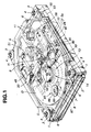
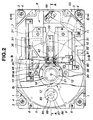
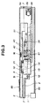
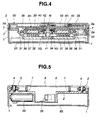
- Figs. 1 to 5 there is shown the drive device of the invention, which is constructed to play or play-back a 3.5 inch type magnet-optical disc which is designated by reference D.
- the drive device is shaped into a generally flat rectangular parallelepiped.
- the device comprises a generally rectangular chassis 2 which has both sides equipped with side frames 1 and 1.
- Each side frame 1 is connected at front and rear ends thereof to the chassis 2 through bolts 4 and insulators 3. Due to provision of the insulators 3, the chassis 2 is protected from external vibration.
- a top cover 5 Above the chassis 2, there is arranged a top cover 5.
- the chassis 2 is formed therearound with a side wall 2a which projects upward, and the top cover 5 is formed therearound with a side wall 5a which projects downward.
- Four bolts 6 are used for uniting the chassis 2 and the top cover 5.
- a gasket 7 Between the side wall 2a of the chassis 2 and the side wall 5a of the top cover 5, there is compressed a gasket 7.
- a substantially sealed container space 8 is defined by the chassis 2 and the top cover 5.
- a disc driving mechanism 9 for rotating the magnet-optical disc there are arranged a disc driving mechanism 9 for rotating the magnet-optical disc, a moving mechanism 10 for moving a magnetic field modulation head H and an optical unit 30 in a radial direction of the disc D and a optical pick-up mechanism 11 for picking up a laser beam which has been emitted therefrom toward the disc D and reflected by the disc D.
- the optical unit 30 constitutes a part of the optical pick-up mechanism 11.
- the disc driving mechanism 9 comprises a spindle motor 13 which is mounted on the chassis 2 through bolts 12.
- the motor 13 has a projected drive shaft 14 which is rotated when the motor 13 is energized.
- An upper circular end 14a of the drive shaft 14 is formed at a center thereof with a threaded bolt opening 15.
- the circular end 14a is further formed therearound with an annular recess 14b.
- the magnet-optical disc D is detachably connected to the drive shaft 14.
- an annular lower spacer 16 an annular upper spacer 17, a circular press plate 18 and a threaded bolt 21 are used, as shown in Fig. 6A.
- the spacers 16 and 17 are made of metal or rubber materials.
- the circular press plate 18 is formed with a center opening 19, and as is seen from Fig. 6B, is formed at its peripheral lower surface with an annular ridge 18a.
- the lower spacer 16 is put on the annular recess 14b of the shaft 14, and the disc D is put on the lower spacer 16 having the upper circular end 14a of the shaft 14 received in a center opening 20 of the disc D.
- the upper spacer 17 and the circular press plate 18 are put on the disc D in order.
- the bolt 21 is inserted into the opening 19 of the press plate 18, the upper spacer 17, the opening 20 of the disc D and the lower spacer 16, and screwed into the bolt opening 15 of the drive shaft 14 driven by the motor 13.
- the disc D is tightly connected to the drive shaft 14 as is seen from Fig. 6B. That is, with the annular ridge 18a of the circular press plate 18 pressed against the disc D by the bolt 21, the disc D is pressed against the drive shaft 14. That is, the peripheral portion of the opening 20 of the disc D is evenly pressed against the annular recess 14b of the shaft 14, minimizing undesired deflection which would be produced on the disc D. This facilitates the focusing of a laser beam on the disc D. Because the disc D can be connected to the drive shaft 14 by means of a so-called "multi-point connection" provided by the annular ridge 18a of the circular press plate 18, the disc D, which is constructed of fragile material, is suppressed from being broken upon the connection. Usage of the lower and upper annular spaces 16 and 17 whose flattening is easily made can promote the above-mentioned multi-point connection. Thus, smoothed and well balanced rotation of the disc D is achieved.
- the disc D is constructed of an optical glass and so sized that the outer diameter is 95 mm, the inner diameter is 15mm to 25mm and the thickness is 0.8 mm.
- the disc D has substantially the same size as a conventional magnetic hard disc.
- the disc D is somewhat thinner than the conventional hard disc. Since the disc D is somewhat larger in diameter than a conventional cartridge type 3.5 inch magnet-optical disc, a larger memory capacity is given to the disc D.
- the disc D is constructed of an optical glass, not a plastic, undesired deflection of the disc D under rotation thereof is suppressed or at least minimized. Thus, the rotation speed of the disc D can be increased correspondingly.
- Fig. 7 shows a sectional view of the magnet-optical disc D.
- the disc D comprises a glass base 25, a molybdenum (Mo) film 26 lined on an upper surface of the glass base 25, an aluminum reflecting film 27 lined on the molybdenum film 26 and a UV plastic film 28 lined on the reflecting film 27.
- the exposed surface of the UV plastic film 28 is polished to have the surface roughness of about 0.2 micrometer.
- an after-mentioned flying type magnetic field modulation head H can be used.
- the magnet-optical disc D is thereafter formed..with a spiral data track T1.
- Designated by reference T2 is a centering track which has been previously stored in a peripheral portion of the disc D.
- the centering track T2 is concentric with the center opening 20.
- the track-to-track distance can be reduced and thus the memory capacity of the disc D can be increased correspondingly.
- Every kinds of photo-electromagnetic discs can be properly connected to the drive shaft 14 so long as they have centering tracks T2. This means that a recorded disc D can be also applied to the drive shaft 14.
- centering track T2 other types of centering track may be used, which are, for example, a track having evenly spaced blanks, a track extending around the center opening 20 and the like.
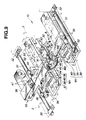
- the moving mechanism 10 is clearly shown in Fig. 9.
- the moving mechanism 10 functions to move the magnetic field modulation head H and the optical unit 30 in the radial direction of the disc D.
- the moving mechanism 10 comprises two parallel guide rails 31 which are secured to the chassis 2 through connecting brackets 32.
- the guide rails 31 (not shown in Fig. 1) are cylindrical and extend in the direction in which the disc D is conveyed or moved.
- a slider 33 which slides along the guide rails 31 has a generally U-shaped construction including a lower flat part 34, an upper flat part 35 and a strut part (no numeral) through which the lower and upper flat parts 34 and 35 are united.
- the disc D is horizontally arranged between the lower and upper flat parts 34 and 35.
- the lower horizontal part 34 has three portions each having a pair of rollers 36 which roll on one of the guide rails 31. As shown, each pair of the rollers 36 are inclined about 90 degrees relative to each other.
- the slider 33 can smoothly slide on and along the guide rails 31 keeping the disc D at the same position. That is, the slider 33 can move in the radial direction of the disc D.
- the slider 33 is driven by a drive force produced by a pair of voice coil motors M1. These motors M1 are arranged to put therebetween the optical unit 30.
- Each voice coil motor M1 comprises an outside yoke 37, a magnet 38 and an inside yoke 39 which are secured to the chassis 2 and a coil 40 which is secured to the lower flat part 34 of the slider 33.
- the outside yokes 37, the magnets 38 and the inside yokes 39 of the two motors M1 extend in the same direction as the guide rails 31 extend.
- the magnet 38 is mounted on the outside yoke 37, and the inside yoke 39 is mounted on the magnet 38 with a certain space defined therebetween.
- the coil 40 of each motor M1 is arranged to spacedly enclose the corresponding inside yoke 39.
- the slider 33 slides in the direction of the arrow A or B depending on the direction of the current which flows in the coils 40.
- the lower flat part 34 of the slider 33 carries the optical unit 30 and the upper flat part 35 carries the magnetic field modulation head H.
- the optical unit 30 comprises a beam reflecting mirror 41 secured to a lower portion of the lower flat part 34.
- the mirror 41 is inclined by about 45 degrees relative to the lower flat part 34.
- the mirror reflects a laser beam from an after-mentioned Galvano-mirror toward an objective lens 42 and vice versa.
- a pair of spring plates 43 are connected at one ends to the lower flat part 34.
- the spring plates 43 hold at their leading ends the objective lens 42.
- the objective lens 42 is positioned just above the beam reflecting mirror 41. Due to the nature of the spring plates 43, the objective lens 42 can move upward and downward.
- the objective lens 42 is moved by a drive force produced by a pair of voice coil motors M2. These motors M2 are arranged to put therebetween the objective lens 42.
- each voice coil motor M2 comprises a yoke 44 and a magnet 45 which are secured to the lower flat part 34 and a coil 46 which is secured to the objective lens 42.
- the lens 42 moves in the direction of the arrow C or D depending on the direction of the current which flows in the coils 46.
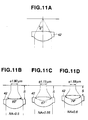
- the objective lens 42 has the numerical aperture (NA) which is equal to or greater than 0.55.
- NA n x Sin ⁇
- the distance "S" between the lens 42 and the disc D and the spot diameter " ⁇ " of the laser beam from the lens 42 can be reduced.
- track density of the disc D can be increased.
- NA numerical aperture
- the magnet-optical disc D is used without using a case therefor.
- the objective lens 42 can be positioned very near the disc D, which induces increase in track density of the disc D.
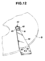
- the magnetic field modulation head H is held by one end of a spring plate 48 which is connected at the other end to the upper flat part 35 of the slider 33 through bolts 47.
- the spring plate 48 extends in a direction perpendicular to the direction in which the slider 33 moves.
- the head H is formed at its lower surface with two spaced ridges 49.
- a head element 50 is arranged between the two ridges 49.
- the head element 50 is positioned above the objective lens 42 and so constructed as to selectively produce bidirectional magnetic field which runs perpendicular to the surface of the disc D.
- the head H is thus of a flying type in which when the disc D is rotated at a high speed, the spring plate 48 is flexed away from the disc D due to an air flow produced by the rotating disc D.
- the head D can be positioned very near the upper surface of the disc D.
- the flying height of the head H can be smaller than 10 microns. This means that the magnetic field modulation is achieved by relatively weak power.
- the spring plate 48 extends in the direction perpendicular to the direction in which the slider 33 moves, the movement of the slider 33 does not need so large space. If the spring plate 48 is arranged to extend in the direction in which the slider 33 moves, the movement needs a larger space and thus the entire construction of the device becomes large in size.
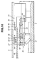
- a head resting structure 51 has an elongate shape which extends in the direction in which the slider 33 moves.
- the structure 51 has a base end secured to the chassis 2.
- the leading or free end of the structure 51 is positioned above the peripheral portion of the disc D.
- the leading end is formed with a tapered upper surface 52 which tapers toward the end.
- the upper surface other than the tapered surface 52 is flat, which is designated by numeral 53.
- head resting structure 51 In place of the above-mentioned head resting structure 51, another type resting structures may be used, one of which is a type of gripping the spring plate 48 with lower and upper fingers. Furthermore, if desired, the head resting structure 51 may be positioned at an inboard side with respect to the disc D.
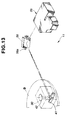
- the opticalpick-up mechanism 11 has an optical path system which comprises a fixed optical device 55 secured to the chassis 2, a Galvano-mirror 56 pivotally mounted on the chassis 2 and the above-mentioned optical unit 30 mounted on the slider 33.
- the fixed optical device 55 comprises a laser diode 57 and a photo detector 58.
- Laser beams (wave length: 780 or 680 nanometer) emitted from the laser diode 57 are converged by a collimator lens 59 to constitute parallel laser beams.
- the parallel laser beams then enter a beam splitter 60 to be directed toward the Galvano-mirror 56. While, laser beams returned back through the Galvano-mirror 56 pass through a part of the beam splitter 60, a 1/2 lambda plate 61, a collimator lens 62 and a concave lens 63 to be focused on the photo detector 58.
- the Galvano-mirror 56 has a horizontal pivot shaft 56a for pivotal movement about the axis of the shaft 56a. Due to the pivotal movement of the Galvano-mirror 56, the direction in which the laser beams from the mirror 56 advance changes in the direction of the radius of the magnet-optical disc D. For the pivotal movement of the Galvano-mirror 56, an electric motor M3 (see Fig. 15) is used.
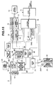
- FIG. 15 A block diagram of the magnet-optical disc drive device is shown in Fig. 15.
- denoted by numeral 70 is a data buffer which exchanges data with a host-computer through a SCSI interface 71.
- the data of the data buffer 70 are outputted to a data modulating part 72.
- the data modulating part 72 modulates the data and outputs the modulated data to a laser driving part 73.
- the laser diode 57 emits laser beams.
- the reflected laser beams from the disc D are detected by the photo detector 58 which outputs a signal representative of information possessed by the reflected laser beams.
- the signal is treated by a signal processing part 74.
- the signal processing part 74 on the basis of a given read clock, address data and user data are regenerated and the position detecting signal is also regenerated.
- the regenerated address data and user data are outputted to a data demodulating part 75 and demodulated.
- the address data and the position detecting signal are fed to a system controller 76.
- the system controller 76 controls various drive circuits 77, 80, 82 and 83 and first and second switches SW1 and SW2 in accordance with command signals fed thereto through the SCSI interface 71. Furthermore, the system controller 76 controls a coil energizing part 84 of the head element 50. The system controller 76 carries out programmed operation steps shown in flowcharts of Figs. 16 to 18, which will be described hereinafter.
- the first switch SW1 changes the clock frequency applied to the drive circuit 77 of the spindle motor 13. That is, based on a switch control signal from the system controller 76, the first switch SW1 selects either the output from one oscillator 78 for normal speed or the output from another oscillator 79 for high speed.
- the second switch SW2 switches a signal fed to the drive circuit 80 of the voice coil motor M1 for the slider 33. That is, based on a switch control signal from the system controller 76, the second switch SW2 selects either a drive control signal from the system controller 76 or a rest signal from a certain voltage source 81. When the second switch SW2 selects the rest signal, the slider 33 is moved to the rest position.
- the interface circuit 71, the system controller 76, the various drive circuits 77, 80, 82 and 83, the data modulating parts 72 and 75 and the data buffer 70 are all mounted on a circuit board 93.
- the circuit board 93 is arranged beneath a lower surface of the chassis 2.
- the top cover 5 is equipped with a breathing structure 85.
- the breathing structure 85 comprises a filter element 87 which fills an aperture 86 formed in the top cover 5.
- a circular adhesive plate 88 connects the filter element.87 to the top cover 5.
- the plate 88 is formed with a small aperture 89 through which the container space 8 and the outside are communicated.
- the pressure in the container space 8 is kept equal to the outside pressure, and due to provision of the filter element 87, dusts or the like in the outside are prevented from entering the space 8.
- the air cleaner structure 90 comprises a duct 91 and a filter element 92 installed in the duct 91.
- the filter element 92 has a layered structure.
- the chassis 2, the top cover 5 and parts which define the enclosed space 8 are all coated with a cation paint.
- the thickness (viz., the distance between an upper end of the top cover 5 and a lower end of the chassis 2 to which the circuit board 93 is mounted) of the drive device of the invention is smaller than 1 inch (viz., 25.4 mm).
- the magnetic field modulation head H assumes the rest position as shown by the broken lines, and the magnet-optical disc D is at a standstill.
- the system controller 76 feeds the first switch SW1 with a switching command signal (S-2). With this, the first switch SW1 switches to connect with the oscillator 79 for high speed (see Fig. 15).
- the drive circuit 77 of the spindle motor 13 is fed with a drive control signal (S-3), and thus the spindle motor 13 starts rotation. Because the drive circuit 77 is operated with a clock from the oscillator 79 for high speed, the spindle motor 13 runs at a higher speed.
- the drive circuit 80 of the voice coil motors M1 on the slider 33 is fed with a drive control signal (S-4).
- the head H is moved away from the rest position separating the spring plate 48 from the head resting structure 51 and brought to an operative position just above the disc D.
- the head H is strongly flexed toward the disc D due to the biasing force which has been stored by the spring plate 48.
- the high speed rotation of the disc D prevents the head H from contacting the disc D. That is, under high speed rotation of the disc D, there is produced therearound an air flow which functions to support the head H.
- the system controller 76 feeds the first switch SW1 with another switching command signal (S-5), so that the first switch SW1 switches to connect with the oscillator 78 for normal speed.
- the drive circuit 77 becomes operated with a clock from the oscillator 78 for normal speed, the spindle motor 13 reduces the speed to a lower normal level.
- the opticalpick-up mechanism 11 When the system controller 76 is fed with a writing or reading command signal from the host-computer, the opticalpick-up mechanism 11 emits a laser beam to the disc D and detects a reflected part of the beam from the disc D. Data possessed by the reflected laser beam is regenerated by the data demodulating part 75 to detect a current address. After calculating the difference or displacement between the current address and a target address (viz., target track), the voice coil motor M1 of the slider 33 is energized. Then, a current address is detected again, and a judgment is carried out as to whether the current address matches with the target address or not. If they do not match with each other, the energization of the voice coil motor M1 is somewhat changed so as to position the current address on the track of the target address (rough seek movement).
- the laser driving part 73 energizes the laser diode 57 and at the same time the coil energizing part 84 energizes the head element 50.
- data possessed by the reflected laser beam detected by the photo detector 58 is converted by the signal processing part 74 to a binary signal and the binary signal is modulated by the data modulating part 75.
- a tracking servo is so made that based on the output from the photo detector 58, the regenerative signal processing part 74 detects the amount of off-tracks, and the system controller 76 controls the drive circuit 83 of the Galvano electric motor M3 in a manner to make the amount of off-tracks zero. That is, the tracking control is carried out by only pivoting the Galvano mirror 56.
- a focus servo is so made that based on the output from the photo detector 58, the signal processing part 74 detects a focus signal, and based on the focus signal, the system controller 76 controls the drive circuit 82 of the voice coil motor M2 of the objective lens 42.
- the system controller 76 carries out the operation which is shown in the flowchart of Fig. 17.
- the system controller 76 feeds the second switch SW2 with a switching command signal (S-12). With this, the second switch SW2 switches to connect with the voltage source 81 for rest, and thus, the voltage of this source 81 is applied to the drive circuit 80 of the voice coil motor M1 of the slider 33. Thus, the slider 33 is moved to the rest position. Thereafter, the system controller 76 stops feeding of the drive control signal to the drive circuit 77 of the spindle motor 13 (S-13) and thus the disc D stops. This condition is maintained until receiving a next command signal.
- the magnetic filed modulating head H is held by the head resting structure 51, and thus the disc D is protected from contacting the head H.
- This is very advantageous because the polished UV plastic coating 28 of the disc D tends to attract neighboring small things.
- the spindle motor 13 is deenergized, energy saving is achieved.
- a command signal (such as, writing command signal or the like) is issued from the host computer (S-1)
- the above-mentioned steps S-2, S-3, S-4 and S-5 are carried out for controlling the spindle motor 13 and the slider 33.
- the system controller 76 carries out the operation which is shown in the flowchart of Fig. 18.
- the system controller 76 feeds the second switch SW2 with a switching command signal (S-32). With this, the second switch SW2 switches to connect with the voltage source 81 for rest, and thus, the voltage of the source 81 is applied to the drive circuit 80 of the voice coil motor M1 of the slider 33. Thus, the slider 33 is moved to the rest position. Thereafter, the system controller 76 stops feeding of the drive control signal to the drive circuit 77 of the spindle motor 13 (S-33) and thus the disc D stops.
Claims (7)
- Dispositif d'entraínement de disque magnéto-optique, comprenant :un mécanisme (9) d'entraínement de disque qui comporte un arbre d'entraínement (14) entraíné par un moteur électrique (13),un dispositif de raccordement temporaire d'un disque magnéto-optique (D) à l'arbre d'entraínement (14),une tête (H) de modulation de champ magnétique placée d'un côté du disque,une unité optique (30) positionnée de l'autre côté du disque (D),un mécanisme (10) de déplacement de la tête (H) de modulation du champ magnétique et de l'unité optique (30) dans la direction radiale du disque, etun dispositif de flottement de la tête (H) dans l'air par utilisation de la force d'un courant d'air qui est produit lorsque le disque est entrainé en rotation,
caractérisé en ce quele dispositif de raccordement comprend :une plaque circulaire (18) de pression placée sur une partie centrale d'une surface du disque,un boulon unique (21) raccordant la plaque circulaire de pression (18) à l'arbre d'entraínement (14) et entre lesquels le disque (D) est disposé intimement,une première entretoise annulaire (17) disposée entre la plaque circulaire de pression (18) et le disque (D),une seconde entretoise annulaire (16) disposée entre l'arbre d'entraínement (14) et le disque (D),un dispositif délimitant une ouverture circulaire centrale (20) dans le disque,une partie circulaire d'extrémité (14a) de plus petit diamètre délimitée par l'arbre d' entraínement (14), cette partie circulaire de plus petit diamètre (14a) étant logée entièrement dans l'ouverture centrale circulaire (20) du disque,une partie circulaire d'extrémité de plus grand diamètre délimitée par l'arbre d'entraínement pour la formation d'un gradin annulaire (14b) sur l'arbre d'entraínement entre les parties circulaires d'extrémité de petit diamètre et de diamètre plus grand, la seconde entretoise annulaire (16) étant logée sur ce gradin annulaire, etun dispositif délimitant une ouverture taraudée (15) destinée à un boulon au centre de la partie circulaire d'extrémité (14a) de plus petit diamètre, l'ouverture taraudée de passage de boulon logeant le boulon unique (21). - Dispositif d'entraínement de disque magnéto-optique selon la revendication 1, caractérisé en ce que le dispositif de flottement comporte une plaque de ressort (48) ayant une première extrémité qui supporte la tête (H) et une autre extrémité qui est raccordée à un coulisseau du mécanisme de déplacement (10).
- Dispositif d'entraínement de disque magnéto-optique selon la revendication 1 ou 2, caractérisé en ce que la plaque circulaire de pression (18) est formée, à sa partie périphérique, avec une arête annulaire repoussée contre la première entretoise annulaire (17).
- Dispositif d'entraínement de disque magnéto-optique selon la revendication 1, 2 ou 3, caractérisé en ce que l'ouverture circulaire centrale (20) est concentrique à une piste de centrage (T2) mémorisée dans le disque.
- Dispositif d'entraínement de disque magnéto-optique selon l'une des revendications précédentes, caractérisé par une structure (51) d'appui de tête qui maintient stationnaire la tête (H) lorsque la tête vient en position de repos.
- Dispositif d'entraínement de disque magnéto-optique selon la revendication 5, caractérisé en ce que la structure d'appui de tête (51) comporte un organe allongé fixé à une partie stationnaire du dispositif d'entraínement de disque, l'organe allongé ayant une grande surface plate (53) sur laquelle se déplace la plaque de ressort lorsque la tête prend la position de repos et une surface d'extrémité (52) de dimension variant progressivement par laquelle la plaque de ressort vient sur la grande surface plate.
- Dispositif d'entraínement de disque magnéto-optique selon l'une des revendications précédentes, caractérisé en ce que l'unité optique comprend :un miroir (41) réfléchissant un faisceau laser,un objectif (42) placé juste au-dessus du miroir, l'ouverture numérique de l'objectif étant supérieure ou égale à 0,55, etune paire de moteurs (M2) à bobine mobile destinés à déplacer l'objectif.
Applications Claiming Priority (3)
| Application Number | Priority Date | Filing Date | Title |
|---|---|---|---|
| JP33773792A JP3364969B2 (ja) | 1992-12-18 | 1992-12-18 | 光磁気ディスクドライブ装置 |
| JP337737/92 | 1992-12-18 | ||
| JP33773792 | 1992-12-18 |
Publications (3)
| Publication Number | Publication Date |
|---|---|
| EP0602677A2 EP0602677A2 (fr) | 1994-06-22 |
| EP0602677A3 EP0602677A3 (fr) | 1995-02-01 |
| EP0602677B1 true EP0602677B1 (fr) | 2000-03-01 |
Family
ID=18311490
Family Applications (1)
| Application Number | Title | Priority Date | Filing Date |
|---|---|---|---|
| EP93120442A Expired - Lifetime EP0602677B1 (fr) | 1992-12-18 | 1993-12-17 | Dispositif d'entraínement de disque magnéto-optique |
Country Status (5)
| Country | Link |
|---|---|
| US (1) | US5448537A (fr) |
| EP (1) | EP0602677B1 (fr) |
| JP (1) | JP3364969B2 (fr) |
| KR (1) | KR100271548B1 (fr) |
| DE (1) | DE69327940T2 (fr) |
Families Citing this family (13)
| Publication number | Priority date | Publication date | Assignee | Title |
|---|---|---|---|---|
| US6141300A (en) | 1989-06-20 | 2000-10-31 | Discovision Associates | Optical actuator including lens assembly with optical axis having symmetric suspensory forces acting thereon and optical disc system including same |
| US5265079A (en) | 1991-02-15 | 1993-11-23 | Applied Magnetics Corporation | Seek actuator for optical recording |
| US5677899A (en) | 1991-02-15 | 1997-10-14 | Discovision Associates | Method for moving carriage assembly from initial position to target position relative to storage medium |
| US6236625B1 (en) | 1991-02-15 | 2001-05-22 | Discovision Associates | Optical disc system having current monitoring circuit with controller for laser driver and method for operating same |
| US6069857A (en) | 1991-02-15 | 2000-05-30 | Discovision Associates | Optical disc system having improved circuitry for performing blank sector check on readable disc |
| US5729511A (en) | 1991-02-15 | 1998-03-17 | Discovision Associates | Optical disc system having servo motor and servo error detection assembly operated relative to monitored quad sum signal |
| US6434087B1 (en) | 1995-01-25 | 2002-08-13 | Discovision Associates | Optical disc system and method for controlling bias coil and light source to process information on a storage medium |
| US5748578A (en) | 1995-01-25 | 1998-05-05 | Discovision Associates | Colpitts type oscillator having reduced ringing and improved optical disc system utilizing same |
| US6091684A (en) | 1995-01-25 | 2000-07-18 | Discovision Associates | Optical disc system and method for changing the rotational rate of an information storage medium |
| JP3409953B2 (ja) * | 1995-11-13 | 2003-05-26 | パイオニア株式会社 | ディスク再生装置 |
| US6058094A (en) * | 1996-07-30 | 2000-05-02 | Seagate Technology Inc. | Flying magneto-optical head with a steerable mirror |
| US6091577A (en) * | 1997-04-18 | 2000-07-18 | Seagate Technology, Inc. | Adjustable head loading apparatus |
| KR100459398B1 (ko) * | 2002-02-06 | 2004-12-03 | 엘지전자 주식회사 | 역전구조 디스크의 광기록재생방법 |
Family Cites Families (8)
| Publication number | Priority date | Publication date | Assignee | Title |
|---|---|---|---|---|
| US4712146A (en) * | 1985-06-04 | 1987-12-08 | Plus Development Corporation | Thin and compact micro-Winchester head and disk assembly |
| JPH03501662A (ja) * | 1988-09-29 | 1991-04-11 | サンドストランド・データ・コントロール・インコーポレーテッド | 無接続体気密光学円盤装置 |
| US5179544A (en) * | 1989-03-28 | 1993-01-12 | U.S. Philips Corporation | Control system for the magnetic head of a magneto-optical disc apparatus |
| EP0403266B1 (fr) * | 1989-06-15 | 1994-08-24 | Matsushita Electric Industrial Co., Ltd. | Appareil d'enregistrement et/ou de reproduction magnéto-optique |
| JPH0340250A (ja) * | 1989-07-06 | 1991-02-21 | Matsushita Electric Ind Co Ltd | 光磁気ディスクおよび光磁気ディスク装置 |
| US5025336A (en) * | 1989-11-06 | 1991-06-18 | Prairietek Corporation | Disk drive apparatus |
| JP3038754B2 (ja) * | 1990-01-20 | 2000-05-08 | ソニー株式会社 | 光磁気ディスクの記録装置 |
| JP3077220B2 (ja) * | 1991-02-23 | 2000-08-14 | ソニー株式会社 | 記録再生装置 |
-
1992
- 1992-12-18 JP JP33773792A patent/JP3364969B2/ja not_active Expired - Fee Related
-
1993
- 1993-12-16 US US08/168,880 patent/US5448537A/en not_active Expired - Fee Related
- 1993-12-17 KR KR1019930028169A patent/KR100271548B1/ko not_active Expired - Fee Related
- 1993-12-17 EP EP93120442A patent/EP0602677B1/fr not_active Expired - Lifetime
- 1993-12-17 DE DE69327940T patent/DE69327940T2/de not_active Expired - Fee Related
Also Published As
| Publication number | Publication date |
|---|---|
| JPH06187689A (ja) | 1994-07-08 |
| KR940016030A (ko) | 1994-07-22 |
| DE69327940D1 (de) | 2000-04-06 |
| KR100271548B1 (ko) | 2000-11-15 |
| EP0602677A3 (fr) | 1995-02-01 |
| JP3364969B2 (ja) | 2003-01-08 |
| EP0602677A2 (fr) | 1994-06-22 |
| US5448537A (en) | 1995-09-05 |
| DE69327940T2 (de) | 2000-07-06 |
Similar Documents
| Publication | Publication Date | Title |
|---|---|---|
| US5448537A (en) | Magnet-optical disc drive device with sure disc placement | |
| EP0537801B1 (fr) | Dispositif pour l'enregistrement et la reproduction de données pour l'utilisation avec une carte optique | |
| US4589102A (en) | Device for compensating the lack of balance of a deviating mirror belonging to an optical system for illuminating a data medium | |
| EP0432779B1 (fr) | Appareil pour le traitement de l'information et tête optique incorporée | |
| EP0154302B1 (fr) | Système optique pour détecter la position d'une lentille d'objectif | |
| US5329503A (en) | Magneto-optical disc recording/reproducing apparatus | |
| US4653856A (en) | Support construction for optical systems | |
| EP0475673B1 (fr) | Appareil pour enregistrer/reproduire des informations | |
| JPH04176025A (ja) | 光学ヘッド | |
| JP3776560B2 (ja) | 光学系駆動装置 | |
| EP1016082B1 (fr) | Appareil de reproduction de disque | |
| JP2566014B2 (ja) | 光学式情報記録再生装置 | |
| JPH07182746A (ja) | 光テープ記録および再生装置 | |
| JPH087538Y2 (ja) | 光磁気記録型記録装置の浮動ヘッド | |
| JPH06243531A (ja) | 光磁気ディスク装置 | |
| JPH02282973A (ja) | 光学的情報記録再生装置 | |
| JP2000242943A (ja) | ディスク装置 | |
| JP2820116B2 (ja) | 光ディスク装置 | |
| KR100284086B1 (ko) | 하드디스크드라이브용 서보트랙라이터와 서보정보기록방법 | |
| JPH01307930A (ja) | 光学的記録再生装置の浮動型ヘッド | |
| JPH08235630A (ja) | 光ディスク装置 | |
| JPH08203090A (ja) | 浮上式光ヘッドのローディング方法及び光ディスク装置 | |
| JPH05217239A (ja) | 光磁気ディスク記録再生装置 | |
| JPH06195850A (ja) | 情報記録再生装置のヘッド構造及びその媒体 | |
| JPH05217240A (ja) | 光磁気ディスク記録再生装置 |
Legal Events
| Date | Code | Title | Description |
|---|---|---|---|
| PUAI | Public reference made under article 153(3) epc to a published international application that has entered the european phase |
Free format text: ORIGINAL CODE: 0009012 |
|
| AK | Designated contracting states |
Kind code of ref document: A2 Designated state(s): DE FR GB |
|
| PUAL | Search report despatched |
Free format text: ORIGINAL CODE: 0009013 |
|
| AK | Designated contracting states |
Kind code of ref document: A3 Designated state(s): DE FR GB |
|
| 17P | Request for examination filed |
Effective date: 19950704 |
|
| 17Q | First examination report despatched |
Effective date: 19970404 |
|
| GRAG | Despatch of communication of intention to grant |
Free format text: ORIGINAL CODE: EPIDOS AGRA |
|
| GRAG | Despatch of communication of intention to grant |
Free format text: ORIGINAL CODE: EPIDOS AGRA |
|
| GRAH | Despatch of communication of intention to grant a patent |
Free format text: ORIGINAL CODE: EPIDOS IGRA |
|
| GRAH | Despatch of communication of intention to grant a patent |
Free format text: ORIGINAL CODE: EPIDOS IGRA |
|
| GRAA | (expected) grant |
Free format text: ORIGINAL CODE: 0009210 |
|
| AK | Designated contracting states |
Kind code of ref document: B1 Designated state(s): DE FR GB |
|
| REF | Corresponds to: |
Ref document number: 69327940 Country of ref document: DE Date of ref document: 20000406 |
|
| ET | Fr: translation filed | ||
| PLBE | No opposition filed within time limit |
Free format text: ORIGINAL CODE: 0009261 |
|
| STAA | Information on the status of an ep patent application or granted ep patent |
Free format text: STATUS: NO OPPOSITION FILED WITHIN TIME LIMIT |
|
| 26N | No opposition filed | ||
| PGFP | Annual fee paid to national office [announced via postgrant information from national office to epo] |
Ref country code: FR Payment date: 20011212 Year of fee payment: 9 |
|
| PGFP | Annual fee paid to national office [announced via postgrant information from national office to epo] |
Ref country code: GB Payment date: 20011219 Year of fee payment: 9 |
|
| REG | Reference to a national code |
Ref country code: GB Ref legal event code: IF02 |
|
| PGFP | Annual fee paid to national office [announced via postgrant information from national office to epo] |
Ref country code: DE Payment date: 20020109 Year of fee payment: 9 |
|
| PG25 | Lapsed in a contracting state [announced via postgrant information from national office to epo] |
Ref country code: GB Free format text: LAPSE BECAUSE OF NON-PAYMENT OF DUE FEES Effective date: 20021217 |
|
| PG25 | Lapsed in a contracting state [announced via postgrant information from national office to epo] |
Ref country code: DE Free format text: LAPSE BECAUSE OF NON-PAYMENT OF DUE FEES Effective date: 20030701 |
|
| GBPC | Gb: european patent ceased through non-payment of renewal fee |
Effective date: 20021217 |
|
| PG25 | Lapsed in a contracting state [announced via postgrant information from national office to epo] |
Ref country code: FR Free format text: LAPSE BECAUSE OF NON-PAYMENT OF DUE FEES Effective date: 20030901 |
|
| REG | Reference to a national code |
Ref country code: FR Ref legal event code: ST |