EP0602778B1 - Etui pour cartes, à circuits amovibles ou portables - Google Patents
Etui pour cartes, à circuits amovibles ou portables Download PDFInfo
- Publication number
- EP0602778B1 EP0602778B1 EP19930308322 EP93308322A EP0602778B1 EP 0602778 B1 EP0602778 B1 EP 0602778B1 EP 19930308322 EP19930308322 EP 19930308322 EP 93308322 A EP93308322 A EP 93308322A EP 0602778 B1 EP0602778 B1 EP 0602778B1
- Authority
- EP
- European Patent Office
- Prior art keywords
- circuit card
- card
- extension module
- base
- electrical connector
- Prior art date
- Legal status (The legal status is an assumption and is not a legal conclusion. Google has not performed a legal analysis and makes no representation as to the accuracy of the status listed.)
- Expired - Lifetime
Links
Images



Classifications
-
- H—ELECTRICITY
- H05—ELECTRIC TECHNIQUES NOT OTHERWISE PROVIDED FOR
- H05K—PRINTED CIRCUITS; CASINGS OR CONSTRUCTIONAL DETAILS OF ELECTRIC APPARATUS; MANUFACTURE OF ASSEMBLAGES OF ELECTRICAL COMPONENTS
- H05K5/00—Casings, cabinets or drawers for electric apparatus
- H05K5/02—Details
- H05K5/0256—Details of interchangeable modules or receptacles therefor, e.g. cartridge mechanisms
- H05K5/026—Details of interchangeable modules or receptacles therefor, e.g. cartridge mechanisms having standardized interfaces
- H05K5/0265—Details of interchangeable modules or receptacles therefor, e.g. cartridge mechanisms having standardized interfaces of PCMCIA type
- H05K5/0273—Details of interchangeable modules or receptacles therefor, e.g. cartridge mechanisms having standardized interfaces of PCMCIA type having extensions for peripherals, e.g. LAN, antennas
-
- G—PHYSICS
- G06—COMPUTING OR CALCULATING; COUNTING
- G06K—GRAPHICAL DATA READING; PRESENTATION OF DATA; RECORD CARRIERS; HANDLING RECORD CARRIERS
- G06K19/00—Record carriers for use with machines and with at least a part designed to carry digital markings
- G06K19/06—Record carriers for use with machines and with at least a part designed to carry digital markings characterised by the kind of the digital marking, e.g. shape, nature, code
- G06K19/067—Record carriers with conductive marks, printed circuits or semiconductor circuit elements, e.g. credit or identity cards also with resonating or responding marks without active components
- G06K19/07—Record carriers with conductive marks, printed circuits or semiconductor circuit elements, e.g. credit or identity cards also with resonating or responding marks without active components with integrated circuit chips
- G06K19/077—Constructional details, e.g. mounting of circuits in the carrier
- G06K19/07743—External electrical contacts
-
- H—ELECTRICITY
- H01—ELECTRIC ELEMENTS
- H01R—ELECTRICALLY-CONDUCTIVE CONNECTIONS; STRUCTURAL ASSOCIATIONS OF A PLURALITY OF MUTUALLY-INSULATED ELECTRICAL CONNECTING ELEMENTS; COUPLING DEVICES; CURRENT COLLECTORS
- H01R12/00—Structural associations of a plurality of mutually-insulated electrical connecting elements, specially adapted for printed circuits, e.g. printed circuit boards [PCB], flat or ribbon cables, or like generally planar structures, e.g. terminal strips, terminal blocks; Coupling devices specially adapted for printed circuits, flat or ribbon cables, or like generally planar structures; Terminals specially adapted for contact with, or insertion into, printed circuits, flat or ribbon cables, or like generally planar structures
- H01R12/70—Coupling devices
- H01R12/7005—Guiding, mounting, polarizing or locking means; Extractors
Definitions
- This invention relates generally to the mechanical design of removable or portable circuit cards which are designed for both compactness and the protection of the internal components of the circuit cards.
- PCMCIA Personal Computer Memory Card International Association
- Cartridges enclosing storage devices for programs such as games have been in use for many years particularly for video games and some microcomputers. Because of their relatively large size physical durability was not a property that was difficult to develop for cartridges. Space was available to build the necessary strength into the components and housings. However, for a circuit card package the size of a credit card physical construction techniques are more limited.
- Memory card devices are illustrated in U.S. patent 4,924,076, issued May 8, 1990 and assigned to Mitsubishi Denki Kabusihiki Kaisha, Japan.
- the devices illustrated incorporate semiconductor devices mounted in an internal base and enclosed in a plastic package formed from two bonded plastic sections.
- U.S. patent 4,386,388 issued May 31,1983 and assigned to Northern Telecom Limited describes a printed circuit board assembly which uses a sheet aluminum cover which loosely encloses a circuit board; abutting edges of the cover are held in a contiguous relationship by inturned edges of the cover which engage small notches in end plates on the circuit board. While this assembly may be satisfactory for larger circuit boards, sufficient strength or stiffness is not likely possible for circuit boards approaching the size of credit cards.
- a preferred form of the circuit card included an internal circuit module which included a circuit component assembly and an electrical connector attached to the component assembly.
- a protective metal covering of thin stainless steel closely girded and substantially enclosed the module in a one piece substantially rigid jacket, while an opening was provided in the jacket to expose an electrical connector so the card could be connected to external equipment such as a computer.
- the circuit module was constructed with a perimeter frame of plastic, which carried a circuit board, electronic components, and an electrical connector. Recesses were provided in the frame for locating the metal covering on the frame while projecting edges or corners of the frame provide concealment for jacket edges and provided impact absorbing corners for the card. No adhesives were necessary to bond the jacket to the frame or other components of the card.
- Memory cards constructed as described were found to able to satisfy the PCMCIA standards version 1 and 2 and were quite durable.
- PCMCIA standard version 1 Credit card sized circuit cards described under the PCMCIA standard version 1 have found substantial acceptance in the electronic industry, but were found wanting in some instances in terms of physical space for components and adaptability to perform additional functions that are desirable. Accordingly PCMCIA standard version 2 was adopted which provided for slightly thicker cards and the option of extending the length of the card to add a rear section that can be considerably thicker than the front portion of the card. Although substantially all of the front portion of the card could be inserted into an electronic device such as a computer for use the rear portion can be quite bulbous and is not conveniently housed within the electronic device with which it is intended to be used. Accordingly when an extended card is in use the rear portion of the card is exposed to possible stresses or damage while in use, (unlike the nonextended version) so it is important that the entire card is strongly constructed, preferably in a unitary structure.
- circuit cards Electrical and mechanical connection of circuit cards is known in the literature; however because of the small size of the circuit cards conforming to the PCMCIA standards the applicant was not able to find any connection means capable of providing secure mechanical and electrical connection between components of the card system while providing a rugged supporting connection between base and extension components.
- U.S. Patent 4,179,178 issued Dec. 18, 1979 to RCA Corporation describes a plug in circuit cartridge with electrostatic charge protection which uses a pair of actuator pins which extend beyond an electrical connector to engage corresponding apertures in a mating assembly to contact a shield device on the mating assembly to raise the shield to permit engagement of the electrical connector.
- the apparatus disclosed is designed to connect a portable cartridge such as a video game cartridge to an electronic device such as a player capable of using it.
- the invention herein overcomes the deficiencies of the prior art while providing a compact tandem circuit card assembly which is convenient from a manufacturing perspective and which is physically durable even if constructed in accordance with PCMCIA standards.
- An extension module is provided by one embodiment of the present invention for tandem connection to a base circuit card.
- the extension module includes a module housing, a pair of spaced apart parallel rigid support fingers extending from the housing, the support fingers being configured for sliding insertion into corresponding parallel sockets in the base circuit card.
- An electrical connector located between said support fingers is adapted for mating connection with a corresponding electrical connector located at the rearward end of the base circuit card when the extension module is connected to the base circuit card.
- a preferred embodiment of the invention is incorporated into a rectangular base circuit card and extension module which are depicted in the drawings.
- the base module will be described in detail first, followed by the extension module, and lastly a description of how they are used together.
- base card 1 is approximately the size of a credit card although somewhat thicker, the length and width being 85.6mm. and 54.0mm. respectively, with a thickness of approximately 5.0mm. conforming to the size specifications outlined by the Personal Computer Memory Card International Association (PCMCIA) for PC memory cards in the September 1991, issue PCMCIA PC Card Standard Release 2.0, which is available from the association.
- PCMCIA Personal Computer Memory Card International Association
- the base card 1 when assembled with extension module 40 meets the PCMCIA standards specified for extended cards.
- cards are designed to be used in personal computers or other devices with suitable sockets as an alternative to disk drives, floppy disks, interfaces, communications or other devices.
- base card 1 is comprised of a circuit module 2 (shown in Fig. 6) which includes integrated circuits or electronic components (not shown) and a first electrical connector 3 connected to the electronic components.
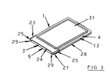
- a protective metal covering in this case of 304L stainless steel sheeting 0.2mm. thick, closely girds and substantially encloses the module 2 in a close fitting one-piece substantially rigid jacket 4, having a top surface 31, bottom surface (not shown) and vertical sidewalls 13.
- jacket 4 includes an opening 5 at the front of the card which exposes part of the first electrical connector 3 so that the card 1 can be connected by means of a suitable socket to a personal computer or other external equipment.
- a similar opening is provided at the rear of the card for exposing rear electrical connector 42 which is used for electrical connection to electrical connector 49 of the extension module 40.
- Jacket 4 provides substantial protection for internal components of module 2 from physical damage and also provides electrical shielding of any sensitive internal components from external static electricity. Physical protection of the circuit module 2 is achieved from the resistance of the metal jacket 4 to external penetration and from the rigidity of the jacket, which when constructed in rectangular configuration as shown, essentially forms a flattened hollow beam, ie. a boxbeam which resists bending, flexing and twisting of the card 1 and circuit module 2 more effectively than other means known to the applicant.
- Circuit module 2 is composed of a partial perimeter frame 6, which advantageously may be constructed of a suitable plastic such as glass filled polycarbonate, eg. LEXAN 500TM (LEXAN 500 is a trade mark of General Electric), which carries a circuit board 7 and electrical connector 3.
- LEXAN 500TM LEXAN 500 is a trade mark of General Electric
- the perimeter frame extends only partially along the edges of the circuit board, leaving the rear portion 48 of the side edges unsupported and exposed internally in the circuit card.
- Circuitry on the card can include read-only storage modules for storage of operational programs or data, and read-write storage modules for use by the external equipment or extension modules to which the card may be connected from time to time.
- the circuitry can be adapted to provide common base functions to permit support for a variety of extension modules to achieve different desired functions.
- Upper cover 4a, and lower cover 4b are assembled about the circuit module to form jacket 4 as described below.
- the covers take the general form of flat based rectangular dishes with bent edges forming perimeter walls.
- the covers shown are essentially mirror versions of each other. Referring to the bottom cover 4b, it may be seen that it has a flat base 12 and upstanding walls 13b along its sides, tabs 14b at the rear end and 29b at the front end.
- each cover A portion of the base of each cover is narrowed to form a plate-like extension 15, for protecting connector 3.
- An insulating layer 16 illustrated may be advantageously incorporated on the interior of each cover to protect internal components.
- the partial perimeter frame 6, which is shown in more detail in Fig. 5, has a number of functions and features. It functions as a carrier for circuit board 7 during the final stages of assembly and testing of the card. It importantly also functions as an internal arbor for locating covers 4a, 4b during assembly to control their alignment for the joining of the covers together. Recessed portions 17 along the sides of the frame, and recesses 19 at the front end of the frame provide this alignment function.
- top (and likewise the bottom) surface 20 of the frame is recessed below protective edges or curb portions 21 of the edges of the frame.
- curbs provide two functions. Curb portions 21 (along the sides of the frame adjacent the position that will be occupied by connector 3), and a similar curb 24 extending along the outer end of connector 3 (see Fig. 4) serve to conceal the unbent edges of covers 4a, 4b from exposure so that the covers can lay below or flush with these frame curbs. If the covers are set below the curbs a degree of protection will be given to artwork present on surfaces of the covers.
- Corners 27 in general provide external shock absorbing material to reduce or prevent damage if the card is dropped.
- the corners also eliminate the need to draw the corners of the covers during their forming stage greatly reducing cost.
- the covers can therefore be produced by simple cutting and bending techniques that are well known.
- Figure 6 shows the covers and circuit module in spaced proximity to each other before assembly.
- Laser welding is particularly suitable for joining the covers as the welding beam can be accurately controlled in energy level, pulse rate, beam size; and depth can be accurately maintained to provide a homogeneous joint 28 without penetrating beyond the stainless steel cover thickness, thus preventing damage to the plastic frame while achieving complete fusion of all abutting wall edges.
- the welding operation produces a one-piece sheet metal jacket of substantial rigidity which girds the frame and protects its internal components.
- the jacket essentially takes the shape of a flattened boxbeam.
- FIG. 3 it can be seen that upper and lower portions of the jacket extend as plates 15 (shown in Fig. 4C) to cover opposite sides of the connector.
- the ends of the extension plates 15 are joined together by straps 29 set in recesses of connector 3 to maintain the integrity and strength of the jacket and card.
- extension plates 15 are somewhat narrower than the rest of the jacket to allow for projection of portions of the perimeter frame in which polarization grooves 25 have been formed to assure correct insertion of the card in cooperative external equipment.
- the embodiment described above provides a durable base card that can be assembled without adhesive being required on the frame or component parts to acquire strength. This has the advantage of reducing the stresses that can be exerted on the circuit board or its components which could otherwise contribute to deterioration of electrical joints and components. In addition, as no adhesive is present, the effect of heat and humidity on adhesive do not become limiting factors on card durability.
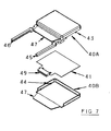
- Extension module 40 is composed of an upper housing shell 40a and a lower housing shell 40b which may be connected together by means of extension locks 43 which engage the inner edges of 40b in known fashion.
- Supporting fingers 45 are formed integrally with housing shell 40a in this example.
- Extension circuit board 41 is designed to be disposed between the housings and expose electrical connector 49 between supporting fingers 45 when so disposed.
- Card standoffs 44 within the housings serve to support extension circuit card as is well understood in the field.
- a longitudinal groove 46 is provided on each of the inwardly opposing faces of the supporting fingers 45 for purposes of slidable engagement to embrace or receive the exposed sides (or edges) 48 of the circuit board 7 when slid within the base card.
- the supporting fingers can be polarized by formation or displacement of the groove on the fingers so that inverted insertion in the base card can be prevented.
- a spring loaded latch pin 51 having a camming front face 52 is disposed to inwardly of each support finger 45, to engage corresponding tabs 14 of said base card 1 when support fingers 45 are fully inserted into card 1. This is well known in the field and so will not be discussed further.
- Upper and lower extension lips 47 on the module serve to shield the upper and lower sides of connector 49 when the extension module is not connected with the base card, and serve to embrace a portion of the top and bottom covering of the base card when fully connected.
- Supporting connector fingers 45 may be cast integrally with housing 40a from a variety of suitable materials such as alloys of aluminum, zinc, magnesium, or Thermosat plastic, or plastic composites such as graphite reinforced composites. Electrostatic shielding properties of materials used for the housings 40a, and b, and fingers 45 may require consideration depending on the circuitry to be used. It is possible to form the supporting fingers separately and secure them to the housing in various fashions, however it is more convenient for manufacturing to form them integrally with the extension housing casting.
- the unsupported side edges 48 of circuit board 7 are exposed to view inside apertures 50 located at the outer ends of the rear edge of the base card.
- the spacing between the circuit card side edges 48 and the corresponding inside portions of the jacket edges adjacent these circuit card side edges essentially define socket-like passages into which supporting fingers 45 may be inserted to be embraced by the inside surfaces of the jacket, and by the edges 48 of the circuit board in this embodiment.
- Support fingers 45 are configured to provide a tight fit within said jacket so that when fully inserted they provide a rigid connection between extension module and base card forming in essence an integral extended circuit card.
- a tandem extended circuit card composed of the base and extension module can be supplied to the end user already assembled or in two sections for user assembly.
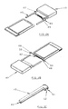
- the user merely inserts the support fingers 45 of extension module 40 into apertures 50 of base card 1 and pushes the two parts together until latch pin 51 engage the corresponding tabs 14A, 14B in base card 1.
- grooves 46 in fingers 45 embrace the unsupported edges 48 of circuit board 7 of the base card to support the board, while the outer surfaces of fingers 45 are themselves embraced tightly by the inner surfaces of the jacket of the base card.
Landscapes
- Engineering & Computer Science (AREA)
- Microelectronics & Electronic Packaging (AREA)
- Computer Hardware Design (AREA)
- Physics & Mathematics (AREA)
- General Physics & Mathematics (AREA)
- Theoretical Computer Science (AREA)
- Credit Cards Or The Like (AREA)
- Coupling Device And Connection With Printed Circuit (AREA)
Claims (12)
- Module d'extension (40) destiné à la connexion en tandem avec une carte de circuit de base (1) comprenant :un boítier de module (40a, 40b),une paire de doigts de support parallèles espacés (45) s'étendant à partir dudit boítier (40a, 40b), lesdits doigts de support (45) étant configurés pour s'introduire par coulissement dans des douilles parallèles correspondantes comportant des ouvertures d'insertion (50) à l'extrémité postérieure de ladite carte de circuit de base (1), etun connecteur électrique (49) situé entre lesdits doigts de support (45), conçu pour se connecter par accouplement avec un connecteur électrique correspondant (3) situé à l'extrémité postérieure de ladite carte de circuit de base (1) lorsque ledit module d'extension (40) est connecté à ladite carte de circuit de base (1),grâce à quoi, lorsque ledit module d'extension (40) est connecté à ladite carte de circuit de base (1) grâce à une insertion pratiquement complète desdits doigts de support (45) dans lesdites douilles de la carte de circuit de base, la venue en contact desdites douilles avec lesdits doigts (45) relie de façon rigide ledit module d'extension (40) à ladite carte de base (1) pour former une carte de circuit étendue intégrale.
- Module d'extension (40) selon la revendication 1, dans lequel ledit connecteur électrique (49) dudit module d'extension (40) est blindé par des lèvres d'extension supérieure et inférieure espacées (47) blindant les côtés supérieur et inférieur du connecteur électrique (49), lesdites lèvres (47) étant positionnées de façon à recouvrir partiellement une partie des surfaces supérieure et inférieure de ladite carte de circuit de base (1) lorsque ledit module d'extension (40) est complètement connecté à ladite carte de base (1).
- Module d'extension (40) selon l'une quelconque des revendications précédentes, comprenant en outre un moyen de verrouillage (51) sur ledit module d'extension (40) destiné à coopérer en enclenchement avec une structure de verrouillage complémentaire (14) sur ladite carte de circuit de base (1) afin de verrouiller ledit module d'extension (40) sur ladite carte de circuit de base (1) lorsqu'ils sont connectés l'un à l'autre.
- Module d'extension (40) selon la revendication 3, dans lequel ledit moyen de verrouillage (51) comprend un ergot chargé par ressort conçu pour s'enclencher avec une patte sur ladite carte de circuit de base (1).
- Module d'extension (40) selon la revendication 1, dans lequel lesdits doigts de support (45) sont composés d'un matériau résistant à la flexion convenable choisi parmi le groupe comprenant un alliage d'aluminium, un alliage de zinc, un alliage de magnésium, une matière plastique thermodurcissable, et un composite de matière plastique et de graphite.
- Ensemble de carte de circuit étendue comprenant un module d'extension (40) et une carte de circuit de base (1), dans lequel ledit module d'extension (40) comprend :un boítier de module (40a, 40 b),une paire de doigts de support parallèles espacés (45) s'étendant à partir dudit boítier, lesdits doigts de support (45) étant configurés pour être introduits de façon coulissante dans des douilles parallèles correspondantes comportant des ouvertures d'insertion (50) à l'extrémité postérieure de ladite carte de circuit de base (1), etun connecteur électrique (49) placé entre lesdits doigts de support (45), conçu pour se connecter par accouplement avec un connecteur électrique correspondant (3) placé à l'extrémité postérieure de ladite carte de circuit de base (1) lorsque ledit module d'extension (40) est connecté à ladite carte de circuit de base (1),grâce à quoi, ledit module d'extension (40) est connecté à ladite carte de circuit de base (1) grâce à une introduction pratiquement complète desdits doigts de support (45) dans lesdites douilles de la carte de circuit de base, la venue en prise desdites douilles avec lesdits doigts (45) relie de façon rigide ledit module d'extension (40) à ladite carte de base (1) afin de former une carte de circuit étendue intégrale.
- Ensemble de carte de circuit étendue selon la revendication 6, dans lequel :ledit module d'extension (40) est conçu pour être connecté en tandem à une carte de circuit de base (1),ladite carte de circuit de base (1) comporte une enveloppe extérieure en matériau en feuille (4) bordant ladite carte (1),les côtés extérieurs desdits doigts de support (45) sont configurés de façon à venir en contact avec les surfaces intérieures de l'enveloppe (4) à proximité des bords latéraux opposés de ladite enveloppe (4) de ladite carte (1), etla venue en contact de ladite enveloppe (4) entourant lesdits doigts (45) relie de façon rigide ledit module d'extension (40) à ladite carte de base (1) afin de former une carte de circuit étendue intégrale.
- Ensemble de carte de circuit étendue selon la revendication 7, dans lequel ladite carte de circuit de base (1) renferme une carte de circuit (7) espacée des surfaces intérieures correspondantes des bords latéraux opposés de l'enveloppe (4), dans lequel les surfaces intérieures opposées desdits doigts dudit module d'extension (40) sont rainurés (46) longitudinalement afin d'entourer des bords transversaux de la carte de circuit (7) contenue à l'intérieur de ladite carte de circuit de base (1).
- Ensemble de carte de circuit étendue selon la revendication 8, dans lequel ladite carte de circuit de base (1) comprend :
un module de circuit comprenant :un cadre périphérique partiel (6),une carte de circuit à composants de circuit (7) supportée au niveau de ses bords par ledit cadre (6), ledit cadre (6) laissant apparente la partie postérieure des bords transversaux de ladite carte,un premier connecteur électrique (3) disposé au niveau de l'extrémité antérieure dudit cadre (6) et relié électriquement à ladite carte de circuit (7),un second connecteur électrique (42) disposé au niveau de l'extrémité postérieure dudit module de circuit, et relié électriquement à ladite carte de circuit (7),une couverture de protection métallique en feuille entourant étroitement ledit cadre périphérique (6) et renfermant pratiquement ledit module de circuit dans une enveloppe pratiquement rigide en une pièce (4),une ouverture (5) dans l'extrémité antérieure de ladite enveloppe (4) coïncidant avec ledit premier connecteur électrique (3) afin de découvrir une partie dudit connecteur électrique (3) pour sa connexion à un équipement externe,une ouverture dans l'extrémité postérieure de ladite enveloppe (4), coïncidant avec ledit second connecteur électrique (42) afin de découvrir une partie dudit connecteur électrique (42) en vue de sa connexion à un module d'extension (40),des ouvertures appariées aux extrémités de l'extrémité postérieure de ladite enveloppe (4) destinées à coopérer avec les doigts de support (45) du module d'extension (40), etles bords latéraux exposés de ladite carte de circuit (7) étant espacés des faces intérieures adjacentes des bords latéraux de ladite enveloppe (4) afin de former une structure en forme de douille entre les bords de la carte de circuit (7) et l'intérieur de l'enveloppe (4) afin de recevoir en les entourant les doigts de support (45) dudit module d'extension (40). - Ensemble de carte de circuit étendue selon l'une quelconque des revendications 6, 7, 8 ou 9, comprenant un moyen de verrouillage (51) sur ledit module d'extension (40) destiné à coopérer en enclenchement avec une structure de verrouillage complémentaire (14) sur ladite carte de circuit de base (1) afin de verrouiller ledit module d'extension (40) sur ladite carte de circuit de base (1) lorsqu'ils sont connectés l'un à l'autre.
- Ensemble de carte de circuit étendue selon la revendication 10, dans lequel ledit moyen de verrouillage (51) comprend un ergot chargé par ressort conçu pour s'enclencher avec une patte (14) sur ladite carte de circuit de base (1).
- Carte de circuit de base (1) composée de
un module de circuit comprenant :caractérisé en ce queun cadre périphérique partiel (6),une carte de circuit à composants de circuit (7) supportée au niveau de ses bords par ledit cadre (6),un premier connecteur électrique (3) disposé au niveau de l'extrémité antérieure dudit cadre (6) et relié électriquement à ladite carte de circuit (7),une couverture de protection métallique en feuille, entourant étroitement ledit cadre périphérique (6) et renfermant pratiquement ledit module de circuit dans une enveloppe pratiquement rigide en une pièce (4),une ouverture (5) dans l'extrémité antérieure de ladite enveloppe (4) coïncidant avec ledit premier connecteur électrique (3) afin de découvrir une partie dudit connecteur électrique (3) en vue de sa connexion à un équipement externe,la carte de circuit de base (1) comprend en outre :la carte de circuit de base est destinée à être utilisée avec un module d'extension (40) comportant des doigts de support appariés (45) et un connecteur électrique (49) permettant la connexion avec ladite carte de circuit de base (1),le cadre périphérique partiel du module du circuit laisse apparente la partie postérieure des bords transversaux de ladite carte,un second connecteur électrique (42) disposé au niveau de l'extrémité postérieure dudit module du circuit, et relié électriquement à ladite carte de circuit (7),une ouverture dans l'extrémité postérieure de ladite enveloppe (4) coïncidant avec ledit second connecteur électrique (42) afin de découvrir une partie dudit connecteur électrique (42) en vue de sa connexion avec un module d'extension (40),des ouvertures appariées aux extrémités de l'extrémité postérieure de ladite enveloppe (4) afin de coopérer avec les doigts de support (45) du module d'extension (40), etles bords latéraux exposés de ladite carte de circuit (7) sont espacés des faces intérieures desdits bords latéraux de ladite enveloppe (4) afin de former une structure en forme de douille entre les bords de la carte de circuit (7) et l'intérieur de l'enveloppe (4), afin de recevoir en les entourant les doigts de support (45) dudit module d'extension (40).
Applications Claiming Priority (2)
| Application Number | Priority Date | Filing Date | Title |
|---|---|---|---|
| CA2083017 | 1992-11-16 | ||
| CA 2083017 CA2083017C (fr) | 1992-11-16 | 1992-11-16 | Cartes de circuits imprimes pour montage en tandem |
Publications (3)
| Publication Number | Publication Date |
|---|---|
| EP0602778A2 EP0602778A2 (fr) | 1994-06-22 |
| EP0602778A3 EP0602778A3 (fr) | 1994-07-20 |
| EP0602778B1 true EP0602778B1 (fr) | 1998-12-23 |
Family
ID=4150698
Family Applications (1)
| Application Number | Title | Priority Date | Filing Date |
|---|---|---|---|
| EP19930308322 Expired - Lifetime EP0602778B1 (fr) | 1992-11-16 | 1993-10-19 | Etui pour cartes, à circuits amovibles ou portables |
Country Status (7)
| Country | Link |
|---|---|
| US (2) | US5513074A (fr) |
| EP (1) | EP0602778B1 (fr) |
| JP (1) | JPH0816858B2 (fr) |
| KR (1) | KR0122536B1 (fr) |
| CN (3) | CN1048565C (fr) |
| CA (1) | CA2083017C (fr) |
| DE (1) | DE69322752T2 (fr) |
Families Citing this family (67)
| Publication number | Priority date | Publication date | Assignee | Title |
|---|---|---|---|---|
| US5991530A (en) * | 1993-02-05 | 1999-11-23 | Canon Denshi Kabushiki Kaisha | Interface device receivable in card storage device slot of host computer |
| CA2138303C (fr) * | 1994-12-15 | 1999-03-30 | Albert John Kerklaan | Boitier de carte de circuit integre |
| US5530622A (en) * | 1994-12-23 | 1996-06-25 | National Semiconductor Corporation | Electronic assembly for connecting to an electronic system and method of manufacture thereof |
| FR2741730B1 (fr) * | 1995-11-23 | 1998-01-02 | Gemplus Card Int | Boitier pour carte amovible enfichable au format etendu |
| US5815120A (en) * | 1996-02-28 | 1998-09-29 | International Business Machines Corporation | Radio frequency local area network adapter card structure and method of manufacture |
| US5805903A (en) * | 1996-05-21 | 1998-09-08 | Compaq Computer Corporation | Protection of computer system against incorrect card insertion during start-up |
| US5752857A (en) * | 1996-05-24 | 1998-05-19 | Itt Corporation | Smart card computer adaptor |
| USD399502S (en) | 1996-10-29 | 1998-10-13 | Intel Corporation | Processor card assembly |
| USD397107S (en) | 1996-10-29 | 1998-08-18 | Intel Corporation | Processor card assembly |
| USD409178S (en) * | 1996-11-01 | 1999-05-04 | Intel Corporation | Processor card assembly |
| USD405440S (en) | 1996-11-01 | 1999-02-09 | Intel Corporation | Processor card assembly |
| USD398592S (en) | 1996-11-08 | 1998-09-22 | Intel Corporation | Processor package |
| USD405772S (en) | 1996-11-15 | 1999-02-16 | Intel Corporation | Processor package cover plate |
| USD413109S (en) | 1996-11-15 | 1999-08-24 | Intel Corporation | Processor package cover plate |
| JPH10154213A (ja) * | 1996-11-22 | 1998-06-09 | Mitsumi Electric Co Ltd | Pcカード |
| JPH10203062A (ja) * | 1997-01-23 | 1998-08-04 | Mitsubishi Electric Corp | 半導体装置カード |
| US5833473A (en) * | 1997-03-12 | 1998-11-10 | Itt Manufacturing Enterprises, Inc. | Cardbus Bridge |
| DE19710513C2 (de) * | 1997-03-13 | 1999-10-14 | Itt Mfg Enterprises Inc | Steckkarte für elektronische Geräte |
| DE19710514C2 (de) * | 1997-03-13 | 2001-06-28 | Itt Mfg Enterprises Inc | Steckkarte für elektronische Geräte |
| DE19710515C1 (de) * | 1997-03-13 | 1998-08-20 | Itt Mfg Enterprises Inc | Steckkarte für elektronische Geräte |
| USD405437S (en) | 1997-05-02 | 1999-02-09 | Intel Corporation | Processor cover plate |
| EP1029429A4 (fr) * | 1997-09-15 | 2001-10-10 | Berg Tech Inc | Carte electronique a extension rf |
| TW354201U (en) * | 1997-10-21 | 1999-03-01 | Hon Hai Prec Ind Co Ltd | Electronic card holder |
| US6434011B1 (en) * | 1997-11-21 | 2002-08-13 | Xybernaut Corporation | PCMCIA compartment |
| DE29722142U1 (de) | 1997-12-16 | 1998-02-12 | Stocko Metallwarenfabriken Henkels & Sohn GmbH & Co, 42327 Wuppertal | Adapter zum Kontaktieren von Chipkarten |
| USD426201S (en) * | 1997-12-22 | 2000-06-06 | Intel Corporation | Processor package |
| TW479817U (en) * | 1998-02-18 | 2002-03-11 | He-Gang Ju | Dual butting horizontal module device |
| US6486994B1 (en) * | 1998-10-13 | 2002-11-26 | 3Com Corporation | Multi-directional infrared port and methods of using same |
| US6345988B1 (en) | 1999-03-12 | 2002-02-12 | 3Com Corporation | Inter-card connection between adjacently positioned expansion cards |
| US6463493B1 (en) | 1999-03-24 | 2002-10-08 | Dell Products L.P. | Adaptive card-sensitive bus slot method and system |
| DE29907373U1 (de) * | 1999-04-26 | 2000-09-07 | ITT Manufacturing Enterprises, Inc., Wilmington, Del. | Vorrichtung zur mechanischen Stabilisierung eines Steckverbinders an einer Leiterplatte und eine mit einer derartigen Vorrichtung versehene Steckkarte für elektronische Geräte |
| DE29909222U1 (de) | 1999-05-28 | 1999-08-05 | STOCKO Contact GmbH & Co. KG, 42327 Wuppertal | PC-Card Chipkartenleser |
| US6174205B1 (en) * | 1999-05-28 | 2001-01-16 | 3Com Corporation | Communication card extension and adapter port |
| FR2812167B1 (fr) * | 2000-07-19 | 2004-09-10 | Fci Besancon Sa | Boitier muni d'une extension d'antenne pour carte electronique et procede d'assemblage du boitier |
| US7107378B1 (en) | 2000-09-01 | 2006-09-12 | Sandisk Corporation | Cooperative interconnection and operation of a non-volatile memory card and an input-output card |
| FI20002869L (fi) | 2000-12-28 | 2002-06-29 | Nokia Corp | Elektroninen laite, elektronisen laitteen lisälaite ja tukielin |
| US6577500B2 (en) | 2001-02-28 | 2003-06-10 | 3Com Corporation | Wireless PC card |
| US6461170B1 (en) | 2001-05-17 | 2002-10-08 | 3Com Corporation | Stacked electronic integrated card assembly with multi-function shared interface |
| JP3691008B2 (ja) * | 2001-09-17 | 2005-08-31 | Tdk株式会社 | Pcカード用ケース及びpcカード |
| WO2003088021A2 (fr) * | 2002-04-08 | 2003-10-23 | Socket Communications, Inc | Module de memoire active sans fil |
| US6865086B2 (en) * | 2002-07-09 | 2005-03-08 | Micron Technology, Inc. | Apparatus and method to secure an adaptor to a reduced-sized memory card |
| JP4100993B2 (ja) * | 2002-08-09 | 2008-06-11 | キヤノン株式会社 | 電子機器 |
| US7367503B2 (en) * | 2002-11-13 | 2008-05-06 | Sandisk Corporation | Universal non-volatile memory card used with various different standard cards containing a memory controller |
| US20050055479A1 (en) * | 2002-11-21 | 2005-03-10 | Aviad Zer | Multi-module circuit card with inter-module direct memory access |
| US8037229B2 (en) | 2002-11-21 | 2011-10-11 | Sandisk Technologies Inc. | Combination non-volatile memory and input-output card with direct memory access |
| US7305535B2 (en) * | 2003-04-17 | 2007-12-04 | Sandisk Corporation | Memory cards including a standard security function |
| US7102891B1 (en) * | 2003-07-23 | 2006-09-05 | Amkor Technology, Inc. | Circuit module having interconnects for connecting functioning and non-functioning add ons and method therefor |
| JP4382460B2 (ja) * | 2003-12-05 | 2009-12-16 | 日本圧着端子製造株式会社 | コンピュータ用カード |
| US7209995B2 (en) * | 2003-12-09 | 2007-04-24 | Sandisk Corporation | Efficient connection between modules of removable electronic circuit cards |
| CA108511S (en) | 2004-04-07 | 2007-03-29 | Nintendo Co Ltd | Information storage cartridge for electronic game machine |
| USD523436S1 (en) * | 2004-11-04 | 2006-06-20 | Hon Hai Precision Ind. Co., Ltd. | Electronic card with improved shielding structure |
| USD564521S1 (en) * | 2006-04-14 | 2008-03-18 | Cisco Technology, Inc. | Wireless notebook adapter |
| USD556763S1 (en) * | 2006-04-26 | 2007-12-04 | D-Link Corporation | Network card |
| USD559256S1 (en) * | 2006-07-17 | 2008-01-08 | Sierra Wireless, Inc. | Wireless electronic communications card |
| US7889507B2 (en) * | 2006-08-30 | 2011-02-15 | Nec Corporation | Portable apparatus |
| USD580442S1 (en) * | 2007-06-08 | 2008-11-11 | Samsung Electronics Co., Ltd. | Lan card for wireless data communication |
| USD573997S1 (en) * | 2007-06-08 | 2008-07-29 | Samsung Electronics Co., Ltd. | LAN card for wireless data communication |
| TW200910537A (en) * | 2007-08-24 | 2009-03-01 | qin-dong Liu | Improved structure of portable flash drive |
| CN101159489B (zh) * | 2007-10-26 | 2011-01-05 | 中兴通讯股份有限公司 | 一种光发送模块的安装装置 |
| USD575787S1 (en) * | 2008-01-03 | 2008-08-26 | Quanta Computer Inc. | Wireless network card |
| USD612385S1 (en) * | 2008-02-28 | 2010-03-23 | Olympus Imaging Corp. | Bar code reader |
| CN101639708B (zh) * | 2008-07-31 | 2012-05-30 | 鸿富锦精密工业(深圳)有限公司 | 触控系统以及移动通讯装置 |
| US8971049B1 (en) * | 2012-06-22 | 2015-03-03 | Motion Computing, Inc. | Portable electronic device having integrated peripheral expansion module |
| RU2016103925A (ru) * | 2013-09-09 | 2017-08-11 | Лэндмарк Графикс Корпорейшн | Создание характеристик виртуального прибора для каротажа в эксплуатационных скважинах для улучшенной адаптации модели |
| CN104619117A (zh) * | 2015-02-20 | 2015-05-13 | 王镇山 | 电路板和电路板间的磁性组合结构 |
| CN107683035A (zh) * | 2017-08-31 | 2018-02-09 | 青岛海尔通信有限公司 | 一种电器产品 |
| US11168919B2 (en) | 2018-05-15 | 2021-11-09 | Johnson Controls Tyco IP Holdings LLP | Removable DIP switch for setting address |
Citations (1)
| Publication number | Priority date | Publication date | Assignee | Title |
|---|---|---|---|---|
| EP0546680A1 (fr) * | 1991-12-09 | 1993-06-16 | International Business Machines Corporation | Carte à circuit dans son enveloppe |
Family Cites Families (24)
| Publication number | Priority date | Publication date | Assignee | Title |
|---|---|---|---|---|
| US4179178A (en) * | 1978-02-02 | 1979-12-18 | Rca Corporation | Plug-in circuit cartridge with electrostatic charge protection |
| US4386388A (en) * | 1981-09-04 | 1983-05-31 | Northern Telecom Limited | Printed circuit board assembly |
| US4480835A (en) * | 1983-03-02 | 1984-11-06 | Williams Theodore R | Cartridge adapter for programmable video games |
| JPH07100088B2 (ja) * | 1986-11-07 | 1995-11-01 | 任天堂株式会社 | ゲ−ム機用カ−トリツジのアダプタ |
| JP2534204B2 (ja) * | 1987-03-31 | 1996-09-11 | 三菱電機株式会社 | 半導体装置カ−ド |
| US4798946A (en) * | 1987-04-09 | 1989-01-17 | Mitsubishi Denki Kabushiki Kaisha | Plastic package for an IC card |
| US4858070A (en) * | 1987-04-24 | 1989-08-15 | Racal Data Communications Inc. | Modular expandable housing arrangement for electronic apparatus |
| JP2539838B2 (ja) * | 1987-07-14 | 1996-10-02 | 三菱電機株式会社 | Icカ−ド装置 |
| JPH0775030B2 (ja) * | 1987-08-07 | 1995-08-09 | 沖電気工業株式会社 | カード型集積回路のコネクタ |
| US4887188A (en) * | 1987-12-22 | 1989-12-12 | Casio Computer Co., Ltd. | Connector for a memory card |
| JPH01175091A (ja) * | 1987-12-28 | 1989-07-11 | Yamaichi Electric Mfg Co Ltd | カードコネクタ |
| US4941841A (en) * | 1988-06-09 | 1990-07-17 | Darden Julius C | Adapter and a removable slide-in cartridge for an information storage system |
| US5112051A (en) * | 1989-06-05 | 1992-05-12 | Westinghouse Electric Corp. | Interfacing device for a computer games system |
| JPH0764143B2 (ja) * | 1989-07-05 | 1995-07-12 | セイコーエプソン株式会社 | メモリカードの静電気除電構造 |
| JPH0648774Y2 (ja) * | 1989-09-21 | 1994-12-12 | 沖電気工業株式会社 | カード型集積回路、並びにコネクタの端子構造 |
| US5155663A (en) * | 1990-02-19 | 1992-10-13 | Fuji Photo Film Co., Ltd. | Memory cartridge system with adapter |
| US5113317A (en) * | 1990-02-20 | 1992-05-12 | Allen-Bradley Company, Inc. | Support for auxiliary circuit card |
| EP0453672B1 (fr) * | 1990-04-26 | 1996-01-03 | Mitsubishi Denki Kabushiki Kaisha | Carte à circuits intégrés |
| US5086336A (en) * | 1990-04-27 | 1992-02-04 | Mitsubishi Denki Kabushiki Kaisha | Semiconductor device card |
| US5125849A (en) * | 1990-07-09 | 1992-06-30 | Amp Incorporated | Connector guide means |
| USD320018S (en) | 1990-12-17 | 1991-09-17 | Bakanowsky Iii Louis J | Combined amplifier and speaker for portable hand held computer game |
| US5193052A (en) * | 1991-11-07 | 1993-03-09 | Advanced Matrix Technology, Inc. | Font cartridge extender with spring hook latch |
| US5225968A (en) * | 1992-03-10 | 1993-07-06 | Ma Hsi K | Connecting apparatus for connecting computer functional cards to a mother board |
| US5282621A (en) * | 1992-11-24 | 1994-02-01 | Tseng Ching J | Universal converter for non-exclusive cards of video game |
-
1992
- 1992-11-16 CA CA 2083017 patent/CA2083017C/fr not_active Expired - Fee Related
-
1993
- 1993-10-16 KR KR1019930021541A patent/KR0122536B1/ko not_active Expired - Fee Related
- 1993-10-19 EP EP19930308322 patent/EP0602778B1/fr not_active Expired - Lifetime
- 1993-10-19 DE DE69322752T patent/DE69322752T2/de not_active Expired - Fee Related
- 1993-10-27 JP JP26891393A patent/JPH0816858B2/ja not_active Expired - Lifetime
- 1993-11-13 CN CN93114515A patent/CN1048565C/zh not_active Expired - Fee Related
- 1993-11-15 US US08/152,786 patent/US5513074A/en not_active Expired - Fee Related
-
1995
- 1995-08-28 US US08/520,844 patent/US5528459A/en not_active Expired - Fee Related
-
1998
- 1998-08-13 CN CNB981184308A patent/CN1156202C/zh not_active Expired - Fee Related
-
1999
- 1999-05-19 CN CN99106650A patent/CN1111822C/zh not_active Expired - Fee Related
Patent Citations (1)
| Publication number | Priority date | Publication date | Assignee | Title |
|---|---|---|---|---|
| EP0546680A1 (fr) * | 1991-12-09 | 1993-06-16 | International Business Machines Corporation | Carte à circuit dans son enveloppe |
Also Published As
| Publication number | Publication date |
|---|---|
| EP0602778A3 (fr) | 1994-07-20 |
| CA2083017C (fr) | 1999-02-09 |
| DE69322752D1 (de) | 1999-02-04 |
| KR0122536B1 (ko) | 1997-11-20 |
| EP0602778A2 (fr) | 1994-06-22 |
| DE69322752T2 (de) | 1999-07-22 |
| KR940013308A (ko) | 1994-06-25 |
| CN1048565C (zh) | 2000-01-19 |
| CN1244768A (zh) | 2000-02-16 |
| JPH06222859A (ja) | 1994-08-12 |
| CN1111822C (zh) | 2003-06-18 |
| US5528459A (en) | 1996-06-18 |
| CN1088013A (zh) | 1994-06-15 |
| JPH0816858B2 (ja) | 1996-02-21 |
| CN1156202C (zh) | 2004-06-30 |
| CN1224988A (zh) | 1999-08-04 |
| CA2083017A1 (fr) | 1994-05-17 |
| US5513074A (en) | 1996-04-30 |
Similar Documents
| Publication | Publication Date | Title |
|---|---|---|
| US5513074A (en) | Tandem circuit cards | |
| US5529503A (en) | Jacketed circuit card | |
| US5502892A (en) | Method of forming a welded encasement for a computer card | |
| CN1089915C (zh) | 屏蔽式存储卡盒 | |
| US6599147B1 (en) | High-density removable expansion module having I/O and second-level-removable expansion memory | |
| US6333854B1 (en) | Memory card | |
| EP0532160B1 (fr) | Système de mise à la masse pour carte | |
| US7121742B2 (en) | Optical module | |
| WO2005001630A2 (fr) | Protection d'un dispositif de stockage de donnees | |
| JPH09185689A (ja) | カードイン形コネクタ | |
| US5485672A (en) | Method for encasing a printed wiring board | |
| JP2004516643A (ja) | 電子カードのアンテナ拡張部を備える容器および該容器の組立て方法 | |
| US6921142B2 (en) | Interchangeable battery pack for a portable computer | |
| EP0697806A1 (fr) | Support pour carte à mémoire à liage thermique | |
| JP3584021B2 (ja) | 外部記憶装置ユニット、及びこれを備えている情報処理装置 | |
| US6628529B2 (en) | Cartridge for a game machine | |
| US6213790B1 (en) | Information processing apparatus | |
| EP0844810B1 (fr) | Carte PC | |
| JP3373804B2 (ja) | カード用コネクタ | |
| JP4086244B2 (ja) | コネクタ | |
| JP2000133968A (ja) | カード型電子機器 | |
| JPH0981264A (ja) | カード状電子機器 | |
| JPH10124627A (ja) | メモリカード装着装置 | |
| TW437121B (en) | Stacked electrical connector assembly | |
| JP2002051246A (ja) | 記録媒体装着装置及びその記録媒体装着装置を備えた電子カメラ |
Legal Events
| Date | Code | Title | Description |
|---|---|---|---|
| PUAI | Public reference made under article 153(3) epc to a published international application that has entered the european phase |
Free format text: ORIGINAL CODE: 0009012 |
|
| PUAL | Search report despatched |
Free format text: ORIGINAL CODE: 0009013 |
|
| AK | Designated contracting states |
Kind code of ref document: A2 Designated state(s): DE FR GB |
|
| AK | Designated contracting states |
Kind code of ref document: A3 Designated state(s): DE FR GB |
|
| 17P | Request for examination filed |
Effective date: 19940927 |
|
| 17Q | First examination report despatched |
Effective date: 19970422 |
|
| GRAG | Despatch of communication of intention to grant |
Free format text: ORIGINAL CODE: EPIDOS AGRA |
|
| GRAG | Despatch of communication of intention to grant |
Free format text: ORIGINAL CODE: EPIDOS AGRA |
|
| GRAG | Despatch of communication of intention to grant |
Free format text: ORIGINAL CODE: EPIDOS AGRA |
|
| GRAH | Despatch of communication of intention to grant a patent |
Free format text: ORIGINAL CODE: EPIDOS IGRA |
|
| GRAH | Despatch of communication of intention to grant a patent |
Free format text: ORIGINAL CODE: EPIDOS IGRA |
|
| GRAA | (expected) grant |
Free format text: ORIGINAL CODE: 0009210 |
|
| AK | Designated contracting states |
Kind code of ref document: B1 Designated state(s): DE FR GB |
|
| REF | Corresponds to: |
Ref document number: 69322752 Country of ref document: DE Date of ref document: 19990204 |
|
| ET | Fr: translation filed | ||
| PGFP | Annual fee paid to national office [announced via postgrant information from national office to epo] |
Ref country code: DE Payment date: 19991006 Year of fee payment: 7 |
|
| PGFP | Annual fee paid to national office [announced via postgrant information from national office to epo] |
Ref country code: FR Payment date: 19991018 Year of fee payment: 7 |
|
| PLBE | No opposition filed within time limit |
Free format text: ORIGINAL CODE: 0009261 |
|
| 26N | No opposition filed | ||
| PGFP | Annual fee paid to national office [announced via postgrant information from national office to epo] |
Ref country code: GB Payment date: 20001003 Year of fee payment: 8 |
|
| PG25 | Lapsed in a contracting state [announced via postgrant information from national office to epo] |
Ref country code: FR Free format text: LAPSE BECAUSE OF NON-PAYMENT OF DUE FEES Effective date: 20010629 |
|
| PG25 | Lapsed in a contracting state [announced via postgrant information from national office to epo] |
Ref country code: DE Free format text: LAPSE BECAUSE OF NON-PAYMENT OF DUE FEES Effective date: 20010703 |
|
| REG | Reference to a national code |
Ref country code: FR Ref legal event code: ST |
|
| PG25 | Lapsed in a contracting state [announced via postgrant information from national office to epo] |
Ref country code: GB Free format text: LAPSE BECAUSE OF NON-PAYMENT OF DUE FEES Effective date: 20011019 |
|
| REG | Reference to a national code |
Ref country code: GB Ref legal event code: IF02 |
|
| GBPC | Gb: european patent ceased through non-payment of renewal fee |
Effective date: 20011019 |