EP0602823B1 - Détection automatique des éléments de réseau accessibles - Google Patents
Détection automatique des éléments de réseau accessibles Download PDFInfo
- Publication number
- EP0602823B1 EP0602823B1 EP93309577A EP93309577A EP0602823B1 EP 0602823 B1 EP0602823 B1 EP 0602823B1 EP 93309577 A EP93309577 A EP 93309577A EP 93309577 A EP93309577 A EP 93309577A EP 0602823 B1 EP0602823 B1 EP 0602823B1
- Authority
- EP
- European Patent Office
- Prior art keywords
- network element
- network
- reachable
- indication
- dsne
- Prior art date
- Legal status (The legal status is an assumption and is not a legal conclusion. Google has not performed a legal analysis and makes no representation as to the accuracy of the status listed.)
- Expired - Lifetime
Links
- 238000001514 detection method Methods 0.000 title claims 3
- 238000004891 communication Methods 0.000 claims description 15
- 238000000034 method Methods 0.000 claims description 9
- 230000005540 biological transmission Effects 0.000 claims 2
- 238000012360 testing method Methods 0.000 description 44
- 230000003287 optical effect Effects 0.000 description 23
- 230000004044 response Effects 0.000 description 19
- 238000010586 diagram Methods 0.000 description 10
- 230000006870 function Effects 0.000 description 9
- 239000003795 chemical substances by application Substances 0.000 description 6
- 230000000694 effects Effects 0.000 description 6
- RGNPBRKPHBKNKX-UHFFFAOYSA-N hexaflumuron Chemical compound C1=C(Cl)C(OC(F)(F)C(F)F)=C(Cl)C=C1NC(=O)NC(=O)C1=C(F)C=CC=C1F RGNPBRKPHBKNKX-UHFFFAOYSA-N 0.000 description 5
- 238000012423 maintenance Methods 0.000 description 3
- 230000002708 enhancing effect Effects 0.000 description 2
- 101710104937 Non-specific acid phosphatase Proteins 0.000 description 1
- 230000008901 benefit Effects 0.000 description 1
- 230000008859 change Effects 0.000 description 1
- 238000011161 development Methods 0.000 description 1
- 239000000835 fiber Substances 0.000 description 1
- 230000003993 interaction Effects 0.000 description 1
- 230000004048 modification Effects 0.000 description 1
- 238000012986 modification Methods 0.000 description 1
Images






Classifications
-
- H—ELECTRICITY
- H04—ELECTRIC COMMUNICATION TECHNIQUE
- H04L—TRANSMISSION OF DIGITAL INFORMATION, e.g. TELEGRAPHIC COMMUNICATION
- H04L41/00—Arrangements for maintenance, administration or management of data switching networks, e.g. of packet switching networks
- H04L41/04—Network management architectures or arrangements
- H04L41/046—Network management architectures or arrangements comprising network management agents or mobile agents therefor
-
- H—ELECTRICITY
- H04—ELECTRIC COMMUNICATION TECHNIQUE
- H04L—TRANSMISSION OF DIGITAL INFORMATION, e.g. TELEGRAPHIC COMMUNICATION
- H04L41/00—Arrangements for maintenance, administration or management of data switching networks, e.g. of packet switching networks
- H04L41/12—Discovery or management of network topologies
-
- H—ELECTRICITY
- H04—ELECTRIC COMMUNICATION TECHNIQUE
- H04Q—SELECTING
- H04Q3/00—Selecting arrangements
- H04Q3/0016—Arrangements providing connection between exchanges
- H04Q3/0062—Provisions for network management
-
- H—ELECTRICITY
- H04—ELECTRIC COMMUNICATION TECHNIQUE
- H04Q—SELECTING
- H04Q2213/00—Indexing scheme relating to selecting arrangements in general and for multiplex systems
- H04Q2213/13516—Indexing scheme relating to selecting arrangements in general and for multiplex systems agents or brokers - user, terminal etc., also OSI agent/managers
Definitions
- This invention relates to digital communications systems and, more particularly, to telecommunications management networks.
- a method for effecting the routing function in a communication network operating under a distributed control protocol.
- selected nodes each maintain a topology database while other nodes (ordinary nodes) only maintain information on local topology.
- the topology databases are maintained in the control nodes in the presence of changes in the network.
- the method also provides for selection of a particular control node from which a particular ordinary node will obtain necessary routing information. More specifically, control nodes identify adjacent control nodes and, upon determining changes in network status, such network status changes are communicated to the adjacent control nodes.
- the ordinary node refers to the single control node co-existing in the ordinary node's domain, from which to obtain information necessary for routing purposes.
- a network element in accordance with the invention is defined in claim 1, and a method in accordance with the invention is defined in claim 7.
- a technical advantage of the invention is that the indications of newly reachable network elements and indications that existing network elements cease to be reachable are maintained automatically and the need for manually inputting such information is eliminated.
- FIG. 1 shows in simplied block diagram form, details of a Network Element 100 (DSNE/NE) which may be employed as either a Directory Services Network Element (DSNE) or a remote Network Element (NE) in a telecommunications management network.
- Network Element 100 is referred to as DSNE/NE 100.
- microprocessor 101 read only memory (ROM) 102, random access memory (RAM) 103, non-volatile memory (FLASH) 104 and direct memory access unit (DMA) 105 which form a local processor complex within DSNE/NE 100.
- ROM read only memory
- RAM random access memory
- FLASH non-volatile memory
- DMA direct memory access unit
- Microprocessor 101 is interfaced via RS-232 driver/receiver 106 and LAPB controller 107 via circuit path 108 to an external network management system (not shown). Operation of units 106 and 107 are well-known in the art. Microprocessor 101 is also interfaced via IEEE 802.3 LAN controller 109 and circuit path 110 to a so-called intra-office local area network (LAN) (not shown). Additionally, microprocessor 101 is interfaced via LAPD controllers 111-1 through 111-N and corresponding optical interfaces 112-1 through 112-N, respectively, to fiber optic links 114-1 through 114-N. Again, LAPD controllers 111 and optical interfaces 112 are well-known in the art.
- FIG. 2 shows, in simplied form, the logical operation of DSNE/NE 100 when configured as DSNE 201 and also as remote NE 204 to effect directory services registration.
- DSNE/NE 100 of FIG. 1 is provisioned to provide Distribution Manager (DM) function 202 and includes a global Directory Information Base (DIB) 203.
- DM Distribution Manager
- DIB Directory Information Base
- DA Distribution Agent
- DSNE/NE 100 of FIG. 1 typically includes all the routines to effect both the functions of DSNE 201 and the functions of remote NE 204 and depending on how it is configured, the appropriate ones of DM 202, DIB 203, DA 205 and cache 206 will be activated.
- FIG. 3 shows in simplied form, an Open System Interconnection (OSI) protocol stack 300 which includes at least network layer 3 including appropriate routing protocols and applications layer 7.
- the OSI protocol stack typically would include other layers for supporting other functionality as desired by the implementor.
- OSI protocol stack is known in the art and is defined in ISO/ICE 7498:1987.
- each layer operates independently of the other layers and was specifically designed to allow interaction between adjacent layers only and not between layers separated by other layers.
- a so-called newly reachable remote NE element, for example, 204 of FIG. 2 is automatically registered in DSNE 201.
- IS-IS Intermediate System-Intermediate System
- ES-IS End System-Intermediate System
- network layer 3 of the OSI protocol stack 300 to dynamically maintain identity information of newly reachable network element 204 in routing table 301 and by enhancing the routing exchange protocol interface to automatically supply an indication that either newly reachable network element 204 has been detected or an indication that an existing network element has ceased to be reachable to applications layer 7 of ISO protocol stack 300 and, specifically, therein to a directory distribution protocol.
- the enhancement to the routing exchange protocol and its interface is shown in FIG. 3A and described below.
- the directory distribution protocol in layer 7 interfaces with distribution manager 202 (FIG. 2) in such a manner as will be described below.
- DSNE 201 and NE 204 will be operating the IS-IS and ES-IS routing protocols so that DSNE 201 will be able to automatically detect the presence of a newly reachable network element or network elements which cease to be reachable. Consequently, the indications of newly reachable network elements and indications that existing network elements cease to be reachable are maintained via distribution manager 202 automatically and the need for manually inputting such information, as was done in the past, is eliminated.
- Protocols IS-IS and ES-IS are well-known in the art and are defined in ISO/IEC 10589:1991 and ISO/IEC 9542:1988, respectively.
- Network layer 3 also includes a connectionless network protocol (CLNP) which provides a connectionless mode of network service, as defined in ISO/IEC 8473:1988.
- Applications layer 7 also includes a subset of the directory services protocol as defined in CCITT Recommendation X.500:1988.
- the associated control service element (ACSE), in applications layer 7, is employed to establish associations between applications routines residing in different network elements, and is defined in CCITT Recommendations X.217 and X.227. Specifically, by way of an example, there would be an association established via ACSE between the distribution manager (DM) in DSNE 201 and the distribution agent (DA) in remote NE 204.
- DM distribution manager
- DA distribution agent
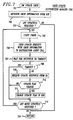
- FIG. 3A is a flow chart illustrating the enchancement made to the routing exchange protocol and its interface in the network layer to automatically supply an indication that either a newly reachable network element has been detected or an indication that an existing network element has ceased to be reachable to applications layer 7 of ISO protocol stack 300 (FIG. 3) and, specifically, therein to a directory distribution protocol.
- the routine of FIG. 3A would typically be stored in flash 104 of the DSNE/NE 100 (FIG. 1) and is employed when provisioned as a DSNE.
- the routing exchange protocol is entered via step 311. Thereafter, step 312 causes the known normal protocol functions of the routing exchange protocol to be performed.
- step 313 tests to determine if any newly reachable network element(s) has been added to the routing table of the routing exchange protocol. If the test result in step 313 is no, step 314 is by-passed and control is passed to step 315. If the test result in step 313 is yes, control is passed to step 314 which generates an indication(s) that a newly reachable network element(s) has been detected which indication is automatically supplied to applications layer 7 and, therein, to the directory distribution protocol. In this manner, the routing exchange protocol interface is enchanced.
- step 315 tests to determine if any network element(s) which is no longer reachable has been removed from the routing tables of the routing exchange protocol. If the test result in step 315 is no, step 316 is by-passed and control is returned to step 312. If the test result in step 315 is yes, control is passed to step 316 which generates an indication(s) that an existing network element(s) has ceased to be reachable and automatically supplies the indication(s) to the applications layer 7 and, therein, to a directory distribution protocol. Again, in this manner the routing exchange protocol interface is enhanced. Thereafter, control is returned to step 312. Again, it is noted that the loop comprising steps 312 through 316 effects the enchancement to the routing exchange protocol and its interface.
- FIG. 4 is a flow chart illustrating the operation of DSNE 201 in automatically registering identity information of remote network elements.
- the routine of FIG. 4 would typically be stored in flash 104 of the DSNE/NE 100 (FIG. 1) and is employed when provisioned as a DSNE.
- step 401 indicates the DSNE 201 startup.
- step 402 causes a routing table to be obtained from network layer 3, specifically routing table 301 of FIG. 3.
- step 403 tests to determine if there are any entries to register in routing table 301.
- the DSNE 201 is going to attempt to register all entries populated in routing table 301.
- the entries in routing table 301 are identity information, i.e., network addresses, of remote network elements forming one or more sub-networks with DSNE 201. If there are entries in routing table 301, step 404 will obtain the next entry. Upon obtaining an entry, step 405 will call a distribution manager (DM) routine which performs the automatic registration of the network address. The distribution manager routine is shown in FIG. 5 and described below. Upon performing the automatic registration in step 405, control is passed to step 406 which tests to determine whether a so-called SONET Management Sub-network Branch (SMSB) should be updated. If the test result in step 406 is yes, then, step 407 calls a DM update SMSB routine to effect the updating of the SMSB automatically.
- SMSB SONET Management Sub-network Branch
- control is returned to step 403, and steps 403 through 406 (or 407) are iterated until all network addresses of remote network elements in routing table 301 (FIG. 3) have been registered.
- steps 403 through 406 or 407 are iterated until all network addresses of remote network elements in routing table 301 (FIG. 3) have been registered.
- control is passed to step 408 where the routine waits until a "newly reachable NE" indication is received from the enhanced routing exchange protocol interface, in accordance with the principles of the invention.
- control is passed to step 409 and the DM registration routine of FIG. 5 is called. Again, the DM registration routine effects the automatic registration of the network address of the newly reachable remote NE.
- control is passed to step 410 which tests to determine whether an SMSB should be updated.
- step 410 If the test result in step 410 is no, control is returned to step 408. If the test result in step 410 is yes, then, step 411 calls a DM update SMSB routine to effect the updating of the SMSB automatically. Thereafter, control is returned to step 408. Details of the DM update SMSB are shown in FIG. 7 and described below.
- FIG. 5 is a flow chart illustrating the operation of the distribution manager (DM) registration routine employed in FIG. 4. Again, this routine is also stored in flash 104 (FIG. 1). Specifically, the DM registration routine is entered via step 501. Thereafter, step 502 starts a timer. The interval of the timer is such as to allow for the automatic registration of a remote network element, e.g., NE 204 (FIG. 2) and is left to the implementor. Step 503 causes DSNE 201 (FIG. 2) to send a registration initialization request to the remote NE 204 and, therein, to a so-called distribution agent (DA) routine which is shown in FIG. 6 and described below.
- DA distribution agent
- Step 504 causes DSNE 201 to wait for either a response from the DA in the remote NE 204 or the time out of the timer in step 502.
- Step 505 tests to determine if the timer has timed out. If the result is yes, the timer has timed out and control is returned to the routine in FIG. 4. If the test result in step 505 is no, step 507 causes DSNE 201 to receive a valid response, i.e., receive registration initialization response from the DA in the remote NE 204.
- Step 508 tests whether the DA in the remote NE 204 successfully provided a valid response. If the test result is no, control is returned via step 506 to the routine of FIG. 4.
- step 508 determines whether the test result in step 508 is yes. If the test result in step 508 is yes, a valid response has been received and step 509 causes the DSNE 201 to receive a registration add request from the DA in the remote NE 204. Thereafter, step 510 tests to determine whether the name and address, i.e., the identity information of the remote NE 204 is valid. If the test result is no, step 511 sends a registration add response error indication to the DA in the remote NE 204 and control is returned via step 506 to the routine shown in FIG. 4. If the test result in step 510 is yes, the identity information of the remote NE 204 is valid and step 512 causes that identity information and an update flag to be added to global DIB 203.
- step 513 automatically causes a registration add response success indication along with identity information of DSNE 201 to the DA in the remote NE 204.
- step 514 tests to determine whether the update flag supplied in step 512 indicates that the SMSB information should be updated. That is, whether or not the newly registered remote NE 204 should receive, identity information of any other network elements in the SMSB including NE 204. If the test result in step 514 is no, control is returned via step 506 to the routine of FIG. 4. If the test result in step 514 is yes, step 515 causes an update SMSB indication to be supplied to the routine of FIG. 4 which, in turn, as indicated above, causes the identity information of the remote NE 204 to be automatically distributed to any other elements in the SMSB including NE 204.
- FIG. 6 is a flow chart of the distribution agent (DA) routine employed in the remote network elements to automatically provide identity information to the DSNE.
- the routine is also typically stored in flash 104 of each of the network elements (FIG. 1).
- the DA routine is entered via step 601.
- step 602 causes the remote NE 204 (FIG. 2) to receive a registration initialization request from the DM routine of FIG. 5 employed in DSNE 201 (FIG. 2).
- step 603 tests to determine whether the registration initialization request is valid. If the test result is no, step 604 causes a registration initialization response error to be sent to the DM routine of FIG. 5 in DSNE 201.
- the routine is exited via step 605.
- step 606 causes a registration initialization response success indication to be sent to the DM routine of FIG. 5 in DSNE 201.
- Step 607 causes a timer to be started. The interval of the timer is such as to allow the identity information of the remote NE 204 to be sent to the DM routine in DSNE 201 and obtain a response indicating reception from the DM routine of FIG. 5 in DSNE 201.
- step 608 causes a registration add request with the NE 204 identity information to be automatically sent to the DM routine in DSNE 201.
- Step 609 causes the DA to wait for a response from the DM or time-out of the timer.
- Step 610 tests to determine if the timer interval has elapsed. If the test result in 610 is yes, no response has been obtained from the DM and the routine is exited via step 605. If the test result in step 610 is no, a response has been obtained from the DM and step 611 causes reception of the registration add response from the DM routine in DSNE 201. Then, step 612 tests to determine whether the received registration add response is valid. If the test result is no, the routine is exited via step 605. If the test result in step 612 is yes, the registration add response is valid and step 613 causes the identity information of DSNE 201 to be stored in local cache 206 (FIG. 2) of NE 204.
- FIG. 7 is a flow chart showing the steps of the DM update SMSB routine of FIG. 4.
- the DM update SMSB routine is entered via step 701.
- the routine is typically stored in flash 104 of the DSNE/NE 100 (FIG. 1) and is employed when provisioned as a DSNE .
- step 702 causes the SMSB identity information to be retrieved from global directory information base (DIB) 203 in DSNE 201 (FIG. 2).
- Step 703 tests to determine if any of the SMSB network elements require to be updated. If the test result is no, control is returned via step 704 to the routine of FIG. 4. If the test result in step 703 is yes, a timer is started.
- DIB global directory information base
- step 706 causes an update request with the SMSB information to be sent to the DA in a network element, e.g. NE 204.
- step 707 causes DSNE 201 to wait for a response or time out of the timer in step 705.
- Step 708 tests to determine if the timer has elapsed. If the test result is yes, control is passed to step 712. If the test result in step 708 is no, step 709 causes DSNE 201 to receive an update response from the DA of the remote NE 204. Then, step 710 tests to determine whether an update flag supplied from the DA in remote NE 204 is changed.
- step 712 tests to determine if any more of the SMSB network elements require to be updated. If the test result in step 712 is no, control is returned via step 704 to the routine of FIG. 4. If the test result in step 712 is yes, then, control is returned to step 705 and steps 705 through 712 are iterated until all necessary network element updates are performed.
- FIG. 8 is a flow chart illustrating the operation of the update SMSB distribution agent routine employed in the remote network elements, e.g., NE 204 (FIG. 2), to automatically update the local cache in the network element.
- the routine is typically stored in flash 104 of each of the network elements.
- the DA update SMSB routine is entered in step 801.
- step 802 causes the network element to receive an update request from the DM in DSNE 201.
- step 803 causes the local cache in NE 204 to be updated with the new SMSB identity information.
- Step 804 causes an update response with an update flag to be sent to the DM in DSNE 201.
- the DA update SMSB routine is exited via step 805.
- FIG. 9 shows, in simplied block diagram form, a sample network 900 incorporating the inventions.
- network management system 901 which may be, for example, a known operations and support system employed to manage a telecommunications network.
- Network management system 901 is interfaced to DSNE 902 which may be, for example, a Digital Access and Cross Connect System (DACS), a digital multiplexer or the like.
- DACS Digital Access and Cross Connect System
- DACS IV-2000 commercially available from AT&T
- DDM-2000 also commercially available from AT&T.
- DSNE 902 and network management system 901 communicate via link 903 using, for example, the known X.25 packet protocol.
- the interface in DSNE 902 to communications link 903 is RS-232 Driver/Receiver 106 and LAPB controller 107.
- DSNE 902 communicates via local area network (LAN) 904 with a number of sub-networks.
- LAN local area network
- DSNE 902 interfaces via LAN 904 with sub-network A, including network elements A1, A2 and A3, sub-network B, including network elements B1, B2, B3 and B4 and sub-network C, including network elements C1, C2, C3 and C4.
- the interface in DSNE 902 to LAN 904 is, in this example, IEEE 802.3 LAN controller 109, which is well known in the art.
- network elements A1, B1 and C1 each interface to LAN 904 via IEEE 802.3 LAN controller 109 (FIG. 1).
- network elements A1, A2 and A3 communicate with each other via optical links.
- network element A1 communications with network element A2 via optical link 905
- network element A2 communicates with network element A3 via optical link 906.
- LAPD controller 111 and optical interface 112 are employed to interface with a corresponding optical link in sub-network A.
- network elements B1, B2, B3 and B4 interface with each other via optical links.
- network element B1 communicates with network element B2 via optical link 907
- network elements B2 and B3 communicate via optical link 908
- network elements B2 and B4 communicate via optical link 909.
- a LAPD controller 111 and an optical interface 112 are employed to interface with each of the corresponding optical links in sub-network B.
- network elements C1, C2, C3 and C4 interface with each other via optical links.
- network elements C1 and C2 communicate via optical link 910
- network elements C2 and C3 communicate via optical link 911
- network elements C3 and C4 communicate via optical link 912
- network elements C4 and C1 communicate via optical link 913.
- a LAPD controller 111 and an optical interface 112 are employed to interface with a corresponding optical link.
- each of the network elements including DSNE 902, has its own unique network address and unique name specific to the telecommunications management network.
- communications among network elements (DSNE and/or NEs) is via a data communications channel (DCC).
- DCC data communications channel
- FIG. 10 is a table of directory information base (DIB) included in DSNE 902 of FIG. 9. Shown are the network names, i.e., target identifiers (TIDs), network addresses, i.e., network service access points (NSAPs) of the network elements and which SMSB the particular network element is included in.
- NSAPs are defined in ISO/IEC 8348:1987/addendum 2:1988. However, for simplicity and clarity of exposition NSAPs having fewer numbers are described here. Thus, for example, DSNE 902 having NSAP "xy 2744" is included in all the SMSB's.
- Network elements A1 through A3 having NSAPs “xy 9247”, “xy 7741” and “xy 1012", respectively, are included in SMSB “A”
- network elements B1 through B4 having NSAPs “xy 2571”, “xy 3314”, “xy 0241” and “xy 4447”, respectively, are included in SMSB “B”
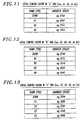
- FIG. 11 shows a table of identity information distributed by DSNE 902 of FIG. 9, in accordance with the principles of the invention, to network elements A1, A2 and A3 of sub-network A. It is noted that the network names and network addresses of the other network elements in the sub-network A and the DSNE are supplied to each network element. Again, the DSNE and NEs A1, A2 and A3 form SMSB "A".
- FIG. 12 is a table of identity information distributed by the DSNE 902 of FIG. 9, in accordance with the principles of the invention, to network elements B1, B2, B3 and B4 of sub-network B.
- the network names and network addresses of the other network elements in the sub-network B and the DSNE are supplied to each of the network elements.
- the DSNE and NEs B1, B2, B3 and B4 form SMSB "B".
- FIG. 13 is a table of identity information distributed by the DSNE 902 of FIG. 9 to network elements C1, C2, C3 and C4 of sub-network C.
- the network names and network addresses of the other network elements in the sub-network C and the DSNE are supplied to each of the network elements.
- the DSNE and NEs C1, C2, C3 and C4 form SMSB "C"
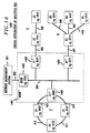
- FIG. 14 shows, in simplied block diagram form, a telecommunications management system 1400 in which network elements, or portions thereof, are integrated with DSNE 1402 to form a single new "DSNE"1401.
- the telecommunications network of FIG. 14, from an apparatus point of view, is similar to that of FIG. 9, except that network elements A 1*, B 1 * and C 1*, or portions thereof as will be explained below, are essentially integrated with DSNE 1402 to form a so-called new "DSNE" 1401, which appears to the sub-networks as a single network element from an OAM&P perspective.
- DSNE 1402 performs both end systems functions, as well as, intermediate systems functions. That is to say, DSNE 1402 is capable of terminating applications messages, as well as, routing and relaying messages to SMSBs A, B and C, in this example.
- Those network elements of network 1400 which are essentially identical to those shown in network 900 of FIG. 9 are similarly numbered and will not be described in detail again.
- new "DSNE” 1401 appears, in accordance with the invention, to be a single integrated DSNE to each of sub-networks A, B and C.
- sub-network A now includes only network elements A2 and A3
- sub-network B now includes network elements B2 through B5
- sub-network C now includes only network elements C2 through C4.
- Network elements A1* (1403), B1* (1404) and C1* (1405) are integrated into new "DSNE” 1401 and appear as “routers” or so-called “intermediate systems” (ISs) to the other network elements in SMSBs A, B and C, respectively.
- new "DSNE” 1401 can provide optical interfaces to each of sub-networks A, B and C of FIG. 14 without the need of expending significant development time and cost.
- DSNE 1402 of FIG. 4 shown in simplified form, are details of DSNE 1402 of FIG. 4. Note that, the only difference between DSNE 1402 of FIG. 15 and DSNE/NE 100 of FIG. 1 are that unnecessary elements have been eliminated. In DSNE 1402 flash memory 104 LAPD controller 111 and optical interfaces 112 have been eliminated. Otherwise, the remaining elements in DSNE 1402 are identical to those in DSNE/NE 100 of FIG. 1 and have been similarly numbered and will not be described again.
- FIG. 16 shown in simplified form, are details of the network elements A 1*, B 1* and C 1* of FIG. 14. Note that the only differences between the network element of FIG. 16 and the network element of FIG. 1 are that the RS-232 driver/receiver 106 and LAPB controller 107 of FIG. 1 have been eliminated. Otherwise, the remaining elements in the network element of FIG. 16 have been similarly numbered to those in FIG. 1 and will not be described again.
- FIG. 17 shows, in simplified form, an implementation of "DSNE" 1401 employing commercially available equipment units.
- a DACS IV-2000 (1702) which is commercially available from AT&T, which would interface with the external network management system (not shown) and interface via a LAN 904 to DDM-2000 digital multiplexer units, or portions thereof (see FIG. 16), namely, 1703, 1704 and 1705 to provide optical interfaces to a plurality of SMSBs A, B and C, respectively.
- the SONET data communications channel from each of the DDM-2000's integrated into the DSNE would be utilized to communicate with remote network elements in each of the sub-networks.
- the SONET data communications channel bytes D1-D3 and/or D4-D12 of the SONET overhead channel.
- FIG. 18 is a table of directory information base (DIB) included in DSNE 1402 of FIG. 14. Shown are the network names (TIDs), network addresses (NSAPs) of the network elements and which SMSB the particular network element is included in. Thus, for example, DSNE 1402 is included in all the SMSBs.
- Network element A1* is included in sub-network A*.
- Network elements A2 and A3 are included in sub-network A.
- Network element B1* is included in sub-network B*.
- Network elements B2 through B5 are included in sub-network B.
- Network element C1* is included in sub-network C*.
- Network elements C2 through C4 are included in sub-network C.
- the network elements having an * indicates that they are integrated into "DSNE" 1401.
- the new single "DSNE" 1402 includes DSNE 1401 and NEs A1*,B1* and C1*.
- FIG. 19 shows a table of identity information distributed by DSNE 1402 to network element A 1*.
- the identity and name of network element A 1* is only shared with DSNE 1402.
- Network element A1* appears transparent to network elements A2 and A3 of sub-network A from an Operations, Administration, Maintenance and Provisioning (OAM&P) perspective.
- OAM&P Operations, Administration, Maintenance and Provisioning
- FIG. 20 shows a table of identity information distributed by DSNE 1402 via network element A 1 * and, hence, "DSNE" 1401 of FIG. 14 to network elements A2 and A3 of sub-network A.
- the network names and network addresses of the other network elements in the sub-network and DSNE 1402 are supplied to each network element in the sub-network A.
- SMSB SMSB
- FIG. 21 shows a table of identity information distributed by DSNE 1402 to network element B 1*.
- the identity and name of network element B 1* is only shared with DSNE 1402.
- Network element B 1 * appears transparent to network elements B2 through B5 of sub-network B from an Operations, Administration, Maintenance and Provisioning (OAM&P) perspective.
- OAM&P Operations, Administration, Maintenance and Provisioning
- FIG. 22 is a table of identity information distributed by DSNE 1402 via network element B 1* and, hence, "DSNE" 1401 of FIG. 14, to network elements B2, B3, B4 and B5 of sub-network B.
- the network names and network addresses of the other network elements in the sub-network B and DSNE 1402 are supplied to each of the network elements.
- "DSNE" 1401 and NEs B2, B3, B4 and B5 form SMSB "B".
- FIG. 23 shows a table of identity information distributed by DSNE 1402 to network element C 1*.
- the identity and name of network element C 1* is only shared with DSNE 1402.
- Network element C1* appears transparent to network elements C2 through C4 of sub-network C from an Operations, Administration, Maintenance and Provisioning (OAM&P) perspective.
- OAM&P Operations, Administration, Maintenance and Provisioning
- FIG. 24 is a table of identity information distributed by DSNE 1402 via network element C1* and, hence, "DSNE" 1401 of FIG. 14, to network elements C2, C3 and C4 of sub-network C.
- the network names and network addresses of the other network elements in the sub-network C and DSNE 1402 are supplied to each of the network elements.
- "DSNE" 1401 and NEs C2, C3 and C4 form SMSB "C".
Landscapes
- Engineering & Computer Science (AREA)
- Computer Networks & Wireless Communication (AREA)
- Signal Processing (AREA)
- Computer And Data Communications (AREA)
- Communication Control (AREA)
- Small-Scale Networks (AREA)
- Data Exchanges In Wide-Area Networks (AREA)
Claims (12)
- Élément de réseau destiné à être utilisé dans un système de transmission numérique comportant au moins un autre élément de réseau caractérisé par :des moyens destinés à permettre l'utilisation d'une pile de protocole d'interface ouverte normalisée (ISO) ayant au moins une couche de réseau ISO comportant des protocoles d'acheminement ISO et une couche d'application comportant un protocole de distribution de répertoire ;des moyens destinés à connecter l'élément de réseau à au moins un autre élément de réseau par l'intermédiaire d'un canal de communication de données, le canal de communication de données étant utilisé pour transporter des données de protocole ISO; et des moyens destinés à utiliser les protocoles d'acheminement ISO pour détecter par l'intermédiaire des données de protocole ISO reçues que cet au moins un autre élément de réseau est devenu accessible et pour fournir automatiquement une indication du fait que cet au moins un autre élément de réseau est accessible au protocole de distribution de répertoire dans la couche d'application.
- Élément de réseau suivant la revendication 1, comportant en outre des moyens destinés à établir une table d'acheminement comportant au moins une indication de cet au moins un autre élément de réseau dans la couche de réseau, une indication du fait que cet au moins un autre élément de réseau devient accessible étant incluse en tant qu'entrée dans la table d'acheminement, et des moyens destinés à permettre un accès direct depuis la couche d'application à la table d'acheminement et aux entrées qu'elle contient dans la couche de réseau.
- Élément de réseau suivant la revendication 2, comportant en outre des moyens destinés à fournir l'indication provenant du protocole de distribution de répertoire dans la couche d'application à un gestionnaire de distribution, le gestionnaire de distribution comportant une base d'informations de répertoire et des moyens destinés à ajouter des informations d'identité d'éléments de réseau nouvellement accessibles à la base d'informations de répertoire.
- Élément de réseau suivant la revendication 2, comportant en outre des moyens destinés à utiliser les protocoles d'acheminement ISO pour détecter par l'intermédiaire des données de protocole ISO reçues que cet au moins un autre élément de réseau a cessé d'être accessible et pour fournir automatiquement une indication du fait que cet au moins un autre élément de réseau cesse d'être accessible au protocole de distribution de répertoire dans la couche d'application, indication que cet au moins un autre élément de réseau a été accessible en ayant été éliminée de la table d'acheminement après la détection du fait qu'il a cessé d'être accessible.
- Élément de réseau suivant la revendication 4, comportant en outre des moyens destinés à fournir l'indication provenant du protocole de distribution de répertoire dans la couche d'application à un gestionnaire de distribution, le gestionnaire de distribution comportant une base d'informations de répertoire et des moyens destinés à éliminer des informations d'identité de cet au moins un autre élément de réseau qui a cessé d'être accessible de la base d'informations de répertoire.
- Élément de réseau suivant la revendication 2, dans lequel l'indication de table d'acheminement est une adresse de cet au moins un autre élément de réseau et dans lequel les moyens d'établissement comportent des moyens destinés à traduire l'adresse de cet au moins un autre élément de réseau en une identité correspondante de cet au moins un autre élément de réseau.
- Procédé destiné à être utilisé dans un élément de réseau devant être utilisé dans un système de transmission numérique comportant au moins un autre élément de réseau, caractérisé par les étapes consistant à :permettre l'utilisation d'une pile de protocole d'interface ouverte normalisée (ISO) ayant au moins une couche de réseau comportant des protocoles d'acheminement ISO et une couche d'application comportant un protocole de distribution de répertoire ;connecter l'élément de réseau à au moins un autre élément de réseau par l'intermédiaire d'un canal de communication de données, le canal de communication de données étant utilisé pour transporter des données de protocole ISO ; etutiliser les protocoles d'acheminement ISO pour détecter par l'intermédiaire des données de protocole ISO reçues que cet au moins un autre élément de réseau est devenu accessible et pour fournir automatiquement une indication du fait que cet au moins un autre élément de réseau est accessible au protocole de distribution de répertoire dans la couche d'application.
- Procédé suivant la revendication 7, comportant en outre les étapes consistant à établir une table d'acheminement comportant des indications d'éléments de réseau dans la couche de réseau, une indication du fait que cet élément de réseau devient accessible étant incluse en tant qu'entrée dans la table d'acheminement, et à permettre un accès direct depuis la couche d'application à la table d'acheminement et aux entrées qu'elle contient dans la couche de réseau.
- Procédé suivant la revendication 8, comportant en outre les étapes consistant à fournir l'indication provenant du protocole de distribution de répertoire dans la couche d'application à un gestionnaire de distribution, le gestionnaire de distribution comportant une base d'informations de répertoire, et à ajouter des informations d'identité d'éléments de réseau nouvellement accessibles à la base d'informations de répertoire.
- Procédé suivant la revendication 8, caractérisé en outre par les étapes consistant à utiliser les protocoles d'acheminement ISO pour détecter par l'intermédiaire des données de protocole ISO reçues qu'un autre élément de réseau a cessé d'être accessible et pour fournir automatiquement une indication du fait que cet élément de réseau cesse d'être accessible au protocole de distribution de répertoire dans la couche d'application, et à effacer une indication du fait que l'élément de réseau a été accessible de la table d'acheminement lors de la détection du fait qu'il a cessé d'être accessible.
- Procédé suivant la revendication 10, caractérisé en outre par les étapes consistant à fournir l'indication provenant du protocole de distribution de répertoire dans la couche d'application à un gestionnaire de distribution, le gestionnaire de distribution comportant une base d'informations de répertoire, et à effacer des informations d'identité d'éléments de réseau qui ont cessé d'être accessibles de la base d'informations de répertoire.
- Procédé suivant la revendication 10, caractérisé en ce que l'indication de table d'acheminement est une adresse de cet au moins un autre élément de réseau et, dans lequel l'étape d'établissement comprend une étape consistant à traduire l'adresse de cet au moins un autre élément de réseau en une identité correspondante de cet au moins un autre élément de réseau.
Applications Claiming Priority (2)
| Application Number | Priority Date | Filing Date | Title |
|---|---|---|---|
| US07/989,615 US5303235A (en) | 1992-12-14 | 1992-12-14 | Automatic detection of reachable network elements |
| US989615 | 1997-12-12 |
Publications (3)
| Publication Number | Publication Date |
|---|---|
| EP0602823A2 EP0602823A2 (fr) | 1994-06-22 |
| EP0602823A3 EP0602823A3 (fr) | 1995-05-03 |
| EP0602823B1 true EP0602823B1 (fr) | 2001-12-19 |
Family
ID=25535282
Family Applications (1)
| Application Number | Title | Priority Date | Filing Date |
|---|---|---|---|
| EP93309577A Expired - Lifetime EP0602823B1 (fr) | 1992-12-14 | 1993-12-01 | Détection automatique des éléments de réseau accessibles |
Country Status (5)
| Country | Link |
|---|---|
| US (1) | US5303235A (fr) |
| EP (1) | EP0602823B1 (fr) |
| JP (1) | JP2883795B2 (fr) |
| CA (1) | CA2109190C (fr) |
| DE (1) | DE69331373T2 (fr) |
Families Citing this family (17)
| Publication number | Priority date | Publication date | Assignee | Title |
|---|---|---|---|---|
| US5422942A (en) * | 1992-09-14 | 1995-06-06 | Sony Corporation | Incoming call transfer terminal |
| US5491817A (en) * | 1993-05-25 | 1996-02-13 | Bell Communications Research Inc. | Linking system and method for accessing directory information about an object in one context when information in another context is known |
| US5583848A (en) * | 1994-11-15 | 1996-12-10 | Telefonaktiebolaget L M Ericsson | Methods for verification of routing table information |
| US5987521A (en) | 1995-07-10 | 1999-11-16 | International Business Machines Corporation | Management of path routing in packet communications networks |
| US5845081A (en) * | 1996-09-03 | 1998-12-01 | Sun Microsystems, Inc. | Using objects to discover network information about a remote network having a different network protocol |
| US6032175A (en) * | 1996-10-17 | 2000-02-29 | International Business Machines Corporation | Enhanced directory services in compound wide/local area networks |
| JP3884821B2 (ja) * | 1997-03-27 | 2007-02-21 | 株式会社日立製作所 | 分散情報の統合方法及び装置 |
| EP0918412A3 (fr) * | 1997-11-21 | 1999-06-02 | Hewlett-Packard Company | Découverte automatique des dispositifs liés à un réseau |
| US6272400B1 (en) * | 1998-07-13 | 2001-08-07 | Helix Technology Corporation | Vacuum network controller |
| US6701359B1 (en) | 1998-07-28 | 2004-03-02 | International Business Machines Corp. | Apparatus and method for managing a multi-threaded persistent agent management information base including a managed object instance cache |
| US6667960B1 (en) * | 2000-04-29 | 2003-12-23 | Hewlett-Packard Development Company, L.P. | Protocol for identifying components in a point-to-point computer system |
| US7110364B1 (en) * | 2001-04-19 | 2006-09-19 | Fujitsu Limited | Optical link adjacency discovery protocol and an optical network therefor |
| US6950846B2 (en) * | 2001-06-27 | 2005-09-27 | International Business Machines Corporation | Providing a globally consistent desired group of reachable nodes |
| US7403986B1 (en) | 2001-10-18 | 2008-07-22 | Network Equipment Technologies, Inc. | Method for synchronizing circuit related objects between network management systems and network control processors |
| US7302692B2 (en) * | 2002-05-31 | 2007-11-27 | International Business Machines Corporation | Locally providing globally consistent information to communications layers |
| DE50302681D1 (de) * | 2002-11-26 | 2006-05-11 | Siemens Ag | Verfahren zum automatischen konfigurieren von kommunikationsbeziehungen zwischen in einem paketorientierten kommunikationsnetz angeordneten kommunikationseinheiten |
| US7433362B2 (en) * | 2004-11-05 | 2008-10-07 | Sbc Knowledge Ventures, L.P. | System and method for SONET NSAP addressing |
Citations (1)
| Publication number | Priority date | Publication date | Assignee | Title |
|---|---|---|---|---|
| US4644532A (en) * | 1985-06-10 | 1987-02-17 | International Business Machines Corporation | Automatic update of topology in a hybrid network |
Family Cites Families (4)
| Publication number | Priority date | Publication date | Assignee | Title |
|---|---|---|---|---|
| EP0331190B1 (fr) * | 1988-03-04 | 1996-01-03 | Nec Corporation | Méthode de gestion des paramètres d'adresse pour l'interconnexion de réseaux locaux et de réseaux RNIS |
| US5056085A (en) * | 1989-08-09 | 1991-10-08 | Harris Corporation | Flood-and-forward routing for broadcast packets in packet switching networks |
| US5101400A (en) * | 1989-09-29 | 1992-03-31 | At&T Bell Laboratories | Dynamic circuit identifier |
| US5200996A (en) * | 1991-03-15 | 1993-04-06 | Nynex Corporation | Station controller for multi-line pick-up and automatic monitoring of telephone station moves |
-
1992
- 1992-12-14 US US07/989,615 patent/US5303235A/en not_active Expired - Lifetime
-
1993
- 1993-10-25 CA CA002109190A patent/CA2109190C/fr not_active Expired - Lifetime
- 1993-12-01 DE DE69331373T patent/DE69331373T2/de not_active Expired - Lifetime
- 1993-12-01 EP EP93309577A patent/EP0602823B1/fr not_active Expired - Lifetime
- 1993-12-10 JP JP5340917A patent/JP2883795B2/ja not_active Expired - Lifetime
Patent Citations (1)
| Publication number | Priority date | Publication date | Assignee | Title |
|---|---|---|---|---|
| US4644532A (en) * | 1985-06-10 | 1987-02-17 | International Business Machines Corporation | Automatic update of topology in a hybrid network |
Also Published As
| Publication number | Publication date |
|---|---|
| EP0602823A2 (fr) | 1994-06-22 |
| JP2883795B2 (ja) | 1999-04-19 |
| CA2109190A1 (fr) | 1994-06-15 |
| US5303235A (en) | 1994-04-12 |
| DE69331373D1 (de) | 2002-01-31 |
| JPH06284132A (ja) | 1994-10-07 |
| CA2109190C (fr) | 1999-12-14 |
| EP0602823A3 (fr) | 1995-05-03 |
| DE69331373T2 (de) | 2002-08-14 |
Similar Documents
| Publication | Publication Date | Title |
|---|---|---|
| EP0602824B1 (fr) | Appareil et méthode d'enregistrement automatique d'informations d'identité d'éléments de réseau | |
| US5537547A (en) | Automatic network element identity information distribution apparatus and method | |
| EP0602823B1 (fr) | Détection automatique des éléments de réseau accessibles | |
| US5513171A (en) | Arrangement for dynamically deriving a telephone network management database from telephone network data | |
| US6104701A (en) | Method and system for performing a least cost routing function for data communications between end users in a multi-network environment | |
| US5453979A (en) | Method and apparatus for generating route information for asynchronous transfer mode cell processing | |
| US6246669B1 (en) | Method and system for optimizing connection set-up operations in a high speed digital network | |
| JP3903316B2 (ja) | ネットワークエンドデバイスの物理的ロケーションを自動的に識別するシステム | |
| US20020122547A1 (en) | Method and apparatus for telephony route selection | |
| US20010033550A1 (en) | Physical layer auto-discovery for management of network elements | |
| EP0461408B1 (fr) | Méthode et système de gestion d'adresses dans un réseau | |
| EP1009130A1 (fr) | Services de répertoire distribué pour localiser des ressources de réseau dans un trés grand réseau de commutation par paquets | |
| EP0602825B1 (fr) | Intégration logique d'éléments multiples de réseau dans un réseau de gestion de télécommunication | |
| US6993019B2 (en) | Method for mapping translation type in No. 7 gateway signaling network | |
| EP1433283A2 (fr) | Reseau de telecommunications a detection automatique de la topologie et procede de detection associe | |
| US5987520A (en) | Closed user group preprocessing decision for efficient call security validation | |
| EP0998077B1 (fr) | Explorateur de traces et méthode pour explorer des traces dans un réseau de transmission | |
| KR0152390B1 (ko) | 이동통신 시스템에서의 제어국과 기지국간의 다중화된 중계선 경로 구성 및 그 제어방법 | |
| US20020065829A1 (en) | Apparatus and method for synchronizing databases in distributed communication systems | |
| KR20010080170A (ko) | 통신 네트워크에서의 종단 관리 | |
| US7486668B2 (en) | Communicating an identification parameter of a network node | |
| JPH02235460A (ja) | アクセス情報パスの管理方式 |
Legal Events
| Date | Code | Title | Description |
|---|---|---|---|
| PUAI | Public reference made under article 153(3) epc to a published international application that has entered the european phase |
Free format text: ORIGINAL CODE: 0009012 |
|
| AK | Designated contracting states |
Kind code of ref document: A2 Designated state(s): DE ES FR GB IT SE |
|
| PUAL | Search report despatched |
Free format text: ORIGINAL CODE: 0009013 |
|
| AK | Designated contracting states |
Kind code of ref document: A3 Designated state(s): DE ES FR GB IT SE |
|
| 17P | Request for examination filed |
Effective date: 19951019 |
|
| 17Q | First examination report despatched |
Effective date: 19991213 |
|
| GRAG | Despatch of communication of intention to grant |
Free format text: ORIGINAL CODE: EPIDOS AGRA |
|
| GRAG | Despatch of communication of intention to grant |
Free format text: ORIGINAL CODE: EPIDOS AGRA |
|
| GRAH | Despatch of communication of intention to grant a patent |
Free format text: ORIGINAL CODE: EPIDOS IGRA |
|
| GRAH | Despatch of communication of intention to grant a patent |
Free format text: ORIGINAL CODE: EPIDOS IGRA |
|
| GRAA | (expected) grant |
Free format text: ORIGINAL CODE: 0009210 |
|
| AK | Designated contracting states |
Kind code of ref document: B1 Designated state(s): DE ES FR GB IT SE |
|
| PG25 | Lapsed in a contracting state [announced via postgrant information from national office to epo] |
Ref country code: IT Free format text: LAPSE BECAUSE OF FAILURE TO SUBMIT A TRANSLATION OF THE DESCRIPTION OR TO PAY THE FEE WITHIN THE PRESCRIBED TIME-LIMIT;WARNING: LAPSES OF ITALIAN PATENTS WITH EFFECTIVE DATE BEFORE 2007 MAY HAVE OCCURRED AT ANY TIME BEFORE 2007. THE CORRECT EFFECTIVE DATE MAY BE DIFFERENT FROM THE ONE RECORDED. Effective date: 20011219 |
|
| REG | Reference to a national code |
Ref country code: GB Ref legal event code: IF02 |
|
| REF | Corresponds to: |
Ref document number: 69331373 Country of ref document: DE Date of ref document: 20020131 |
|
| PG25 | Lapsed in a contracting state [announced via postgrant information from national office to epo] |
Ref country code: SE Free format text: LAPSE BECAUSE OF FAILURE TO SUBMIT A TRANSLATION OF THE DESCRIPTION OR TO PAY THE FEE WITHIN THE PRESCRIBED TIME-LIMIT Effective date: 20020319 |
|
| ET | Fr: translation filed | ||
| PG25 | Lapsed in a contracting state [announced via postgrant information from national office to epo] |
Ref country code: ES Free format text: LAPSE BECAUSE OF FAILURE TO SUBMIT A TRANSLATION OF THE DESCRIPTION OR TO PAY THE FEE WITHIN THE PRESCRIBED TIME-LIMIT Effective date: 20020627 |
|
| PLBE | No opposition filed within time limit |
Free format text: ORIGINAL CODE: 0009261 |
|
| STAA | Information on the status of an ep patent application or granted ep patent |
Free format text: STATUS: NO OPPOSITION FILED WITHIN TIME LIMIT |
|
| PG25 | Lapsed in a contracting state [announced via postgrant information from national office to epo] |
Ref country code: GB Free format text: LAPSE BECAUSE OF NON-PAYMENT OF DUE FEES Effective date: 20021201 |
|
| 26N | No opposition filed | ||
| GBPC | Gb: european patent ceased through non-payment of renewal fee | ||
| PGFP | Annual fee paid to national office [announced via postgrant information from national office to epo] |
Ref country code: DE Payment date: 20121220 Year of fee payment: 20 Ref country code: FR Payment date: 20130130 Year of fee payment: 20 |
|
| REG | Reference to a national code |
Ref country code: FR Ref legal event code: TP Owner name: ALCATEL-LUCENT USA INC., US Effective date: 20130823 Ref country code: FR Ref legal event code: CD Owner name: ALCATEL-LUCENT USA INC., US Effective date: 20130823 |
|
| REG | Reference to a national code |
Ref country code: DE Ref legal event code: R071 Ref document number: 69331373 Country of ref document: DE |
|
| REG | Reference to a national code |
Ref country code: DE Ref legal event code: R071 Ref document number: 69331373 Country of ref document: DE |
|
| PG25 | Lapsed in a contracting state [announced via postgrant information from national office to epo] |
Ref country code: DE Free format text: LAPSE BECAUSE OF EXPIRATION OF PROTECTION Effective date: 20131203 |
|
| REG | Reference to a national code |
Ref country code: FR Ref legal event code: GC Effective date: 20140410 |
|
| REG | Reference to a national code |
Ref country code: FR Ref legal event code: RG Effective date: 20141015 |