EP0602957A1 - Système et procédé pour la transmission de signaux acoustiques sur une voie optique - Google Patents
Système et procédé pour la transmission de signaux acoustiques sur une voie optique Download PDFInfo
- Publication number
- EP0602957A1 EP0602957A1 EP93310139A EP93310139A EP0602957A1 EP 0602957 A1 EP0602957 A1 EP 0602957A1 EP 93310139 A EP93310139 A EP 93310139A EP 93310139 A EP93310139 A EP 93310139A EP 0602957 A1 EP0602957 A1 EP 0602957A1
- Authority
- EP
- European Patent Office
- Prior art keywords
- electrooptic
- light
- transmitting element
- signal
- signals
- Prior art date
- Legal status (The legal status is an assumption and is not a legal conclusion. Google has not performed a legal analysis and makes no representation as to the accuracy of the status listed.)
- Withdrawn
Links
- 230000005540 biological transmission Effects 0.000 title claims abstract description 49
- 230000003287 optical effect Effects 0.000 title claims description 41
- 238000000034 method Methods 0.000 title claims description 10
- 230000005236 sound signal Effects 0.000 title abstract description 17
- 239000013307 optical fiber Substances 0.000 claims abstract description 7
- 239000002131 composite material Substances 0.000 claims description 9
- 230000005284 excitation Effects 0.000 claims description 6
- 230000010076 replication Effects 0.000 abstract 1
- 230000008054 signal transmission Effects 0.000 description 4
- 238000006243 chemical reaction Methods 0.000 description 3
- 238000010586 diagram Methods 0.000 description 3
- 230000009466 transformation Effects 0.000 description 2
- 239000003990 capacitor Substances 0.000 description 1
- 230000008878 coupling Effects 0.000 description 1
- 238000010168 coupling process Methods 0.000 description 1
- 238000005859 coupling reaction Methods 0.000 description 1
Images

Classifications
-
- H—ELECTRICITY
- H04—ELECTRIC COMMUNICATION TECHNIQUE
- H04B—TRANSMISSION
- H04B10/00—Transmission systems employing electromagnetic waves other than radio-waves, e.g. infrared, visible or ultraviolet light, or employing corpuscular radiation, e.g. quantum communication
- H04B10/50—Transmitters
- H04B10/501—Structural aspects
- H04B10/502—LED transmitters
Definitions
- This invention relates generally to transmission of signals over an optical channel and pertains more particularly to providing audio electrical signals originating at one location at a second location through the use of optical fibers.
- optical transmission links are of known substantial independence in signal transmission as respects EMI and RFI, they are of complexity and component needs beyond that desired in the described automotive environment.
- customary optical link transmission of audio signals involves modulation of a carrier by the audio signals, impression of the modulated carrier on a transmitting LED (light-emitting diode), and demodulation of the receiving LED output to recover the audio signals at the remote location.
- the present invention has as its primary object the provision of such a simpler and less component needy optical transmission arrangement.
- a more particular object of the invention is the provision of improved methods, apparatus and systems for implementing automotive sound systems having optical transmission links.
- the invention provides a method for carrier-less optical transmission of alternating current signals, not requiring ADC or DAC practices or the provision of square-wave optical signals.
- the methods and systems of the invention will be accordingly seen to be simpler and less component involved than heretofore known methods and systems of this general variety.
- the invention provides, in a method for transmission of alternating-current electrical input signals from a point of origin thereof to a location remote from the point of origin, the steps of: selecting for transmission from the point of origin to the remote location an electrooptic transmitting element, an optical transmission link and an electrooptic transducer; preestablishing a datum excitation level of the electrooptic transmitting element to cause the electrooptic transmitting element to apply a datum frequency light signal to the optical transmission link in the absence of the input signals; and generating drive signals for the electrooptic transmitting element having characteristics corresponding with the input signals and applying the drive signals to the electrooptic transmitting element to cause the electrooptic transmitting element to apply to the optical transmission link light signals having frequencies exceeding the datum frequency light signal.
- the first above step is preferably practiced in part by selecting the electrooptic transmitting element to provide diverse light frequency output correspondingly with levels of the drive signals.
- the first step is preferably practiced in further part by selecting the electrooptic transducer to provide diverse output voltage levels correspondingly with light frequencies of light output from the optical transmission link, which is preferably constituted by at least one optical fiber.
- the invention provides a method for the above-noted transmission of an alternating-current electrical input signal from a point of origin thereof to a location remote from the point of origin, comprising the steps of: (a) predetermining an amplitude of the input signal from a zero level thereof to the maximum negative peak thereof (b) forming a composite signal by adding to the input signal at the point of origin thereof a direct-current bias voltage equal to the predetermined amplitude and providing from the composite signal a drive sianal for a light-emitting element; (c) driving the light-emitting element correspondingly with the drive signal and applying the output light from the light-emitting element to an optical transmission link; and (d) applying light transmitted through the optical transmission link to an electrooptic transducer for reconstituting the input signal at the remote location.
- Step b) may be practised in part by selecting said light-emitting element to provide diverse light frequency output correspondingly with levels of said drive signal.
- Step d) may be practised in part by selecting said electrooptic transducer to provide diverse output voltage levels correspondingly with light frequencies of light output from said optical transmission link.
- Step c) may be practised in part by constituting said optical transmission link by at least one optical fiber.
- Step b) may be practised in part by providing said drive signal by generating direct currents proportional in amplitude to voltage levels of said composite signal.
- Step c) may be practised by connecting said light-emitting element in series-circuit with a semiconductive member and applying said drive signal to said semiconductive member.
- Said semiconductive member may be a transistor, said light-emitting element being conductive in series with the collector of said transistor and said drive signal being applied to the base of said transistor.
- a system for transmission of an alternating current electrical input signal from a point of origin thereof to a location remote from said point of origin comprising:
- Apparatus in accordance with a still further aspect of the invention encompasses a light signal transmitter for providing an output light signal corresponding to an input signal having a characteristic varying with time, comprising an electrooptic transmitter device drivable for generating output light signals of diverse light frequencies and drive circuitry for receiving the input signal and for so driving the electrooptic transmitter device responsively thereto to cause generation thereby of output light signals having frequencies differing with time correspondingly with characteristic variations of the input signal, all of such output light signal frequencies exceeding an output light signal frequency of the electrooptic transmitter device generated thereby in the absence of the input signal.
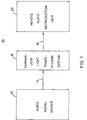
- Fig. 1 is a general block diagram of an arrangement in accordance with the invention.
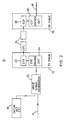
- Fig. 2 is a detailed block diagram of the carrier-less optical transmission system of the Fig. 1 arrangement.
- Fig. 3 is an electrical schematic diagram of a preferred embodiment of the optical transmission system of Fig. 2.
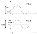
- Figs. 4 and 5 are graphic illustrations explanatory of considerations involved in the invention.
- arrangement 10 includes audio signal source 12, the output of which is applied over line 14 as an input to carrier-less optical transmission system 16, the output of which is in turn furnished over line 18 to remote audio reproduction unit 20.
- Source 12 may comprise an automotive radio, magnetic tape player, or like audio signal generator.
- Remote audio reproduction unit 20 may comprise automotive sound system speakers or remotely located combinations of audio power amplifiers and speakers.
- carrier-less optical transmission system 16 includes an electrooptic transmitting element (ETE) 22, comprising an LED or the like, preferably providing colored output light to verify system operation.
- ETE electrooptic transmitting element
- An optical transmission link (OTL) 24 is preferably constituted by at least one optical fiber and has its input end disposed to receive light output from transmitting element 22.
- the output end of link 24 is disposed to issue transmission light onto electrooptic transducer (EOT) 26, which may also be constituted by an LED or the like.
- EOT electrooptic transducer
- Datum excitation level establishing circuitry (DATUM SET CKT) 28 has as its function the causing of transmitting element 22 to apply a datum frequency light signal to transmission link 24 in the absence of the input signals on line 14.
- Drive signal generator 30 receives the output of DATUM SET 28 and input signals to be transmitted, i.e., those on line 14, and has as its function the providing of drive signals for transmitting element 22.
- the drive signals are applied particularly to transmitting stage (TX STAGE) 32, which includes transmitting element 22 and transmitting element driving circuit (ETE DRIVING CKT) 34.
- a receiving stage (RX STAGE) 36 includes electrooptic transducer 26 and a circuit driven by the transducer (EOT DRIVEN CKT) 38. Stage 36 has as its function the conversion of light output from link 24 to electrical signals and conveyance thereof to line 18.
- the drive signals provided by signal generator 30 have characteristics corresponding with the input signals and drive transmitting element 22 to cause it to apply to transmission link 24 light signals having frequencies exceeding the datum frequency light signal, as is explained below.
- DATUM SET CKT 28 comprises a voltage divider including resistors R1 and R2, which provides at its junction with resistor R3 a voltage which is a predetermined voltage, suitable for datum frequency light generation. This voltage level is applied through R3 to the positive input of amplifier 40.
- Input audio signals on line 14 are coupled through capacitor C1 also to the positive input of amplifier 40.
- the circuitry feeding such input of amplifier 40 can thus be termed a composite signal generator, since, in the presence of audio input signals, the voltage level from resistor R3 is added to the audio signals.
- Drive signal generator 30 further includes resistor R4, coupling the negative input of amplifier 40 to ground and feedback resistor R5, which renders amplifier 40 as an operational amplifier.
- the feedback loop is further inclusive of circuit elements of TX stage 32, as noted below.
- amplifier 40 functions particularly as a precision current source, providing output drive signals to TX stage 32 which are currents having amplitudes proportional to the instantaneous amplitude of signals on line 14.
- TX stage 32 includes transistor 42, the collector of which is connected to the cathode of transmitting element 22, the emitter of which is connected to ground through resistor R6 and the base of which in connected to the output of amplifier 40 Diode D1 is connected in parallel with the base-emitter junction of transistor 42 and serves to preclude signals input to the transistor from being at negative voltages with respect to ground.
- the emitter of transistor 42 is further connected to feedback resistor R5 and accordingly, the feedback loop is inclusive of the base-emitter junction of transistor 42.
- a composite signal for input to amplifier 40 is seen to include a sinusoidal voltage signal, i.e., the audio input signal, all extent (VIN) of which is positive.
- VIN voltage
- VNEG direct current voltage level
- the Fig. 4 waveform is likewise precisely indicative of the output current of amplifier 40.
- Transmitting element 22 is selected to provide light output which varies in frequency with the level of current flowing therethrough.
- Fig. 5 which is a plot of link light frequency (FLINK) versus time (t), thus depicts the frequency output by the transmitting element corresponding with the described current excitation thereof.
- f0 is the light frequency output when there is no audio input signal on line 14, i.e., the datum level light frequency. Accordingly, all light frequencies output by transmitting element 22 in the presence of audio signal input will exceed the datum level light frequency.
- Frequency f mid corresponds with the zero-crossovers of the audio signal and frequency f max corresponds with the positive maximum peak of the audio signal.
- RX stage 36 includes, in addition to electrooptical transducer 26, amplifier 44, rendered in operational amplifier configuration by resistor R7 and transducer 26.
- Amplifier 44 is reverse-connected at its inputs from amplifier 40, i.e., its positive input is grounded and its negative input is connected to receive output current of transducer 26.
- the characteristics of transducer 26 correspond precisely with those of transmitting element 22, namely, it has the same light-to-current characteristic as the current-to-light characteristic of element 22 and is oppositely poled. Operation of RX stage 36 is thus the converse of drive signal generator 30, and the input audio signal on line 14 is replicated as the output audio signal on line 18.
- element 22 and transducer 26 may be constituted by RED visible light emitting diodes op5614.
- element 22 places a range of light frequencies of from a datum level of 650nm to a maximum of 660nm on the optical fiber link, which may be of fifteen meters in length. Harmonic distortion induced by EMI/RFI is found to be less than four-tenths of one percent.
- the voltage divider for setting the datum light frequency may have either of its resistors R1 and R2 in variable resistor form to accommodate on-site adjustment thereof.
- the precision current source for driving the light-transmission element may of course be rendored by other circuitry, as may the TX and RX stages.
- the light-transmitting element and electrooptic transducer may evidently be constituted by other than LEDs. Accordingly, it is to be understood that the particularly disclosed and depicted embodiment and method is intended in an illustrative and not in a limiting sense. The true spirit and scope of the invention are set forth in the following claims and the preceding statements of invention.
Landscapes
- Physics & Mathematics (AREA)
- Electromagnetism (AREA)
- Engineering & Computer Science (AREA)
- Computer Networks & Wireless Communication (AREA)
- Signal Processing (AREA)
- Optical Communication System (AREA)
- Cable Transmission Systems, Equalization Of Radio And Reduction Of Echo (AREA)
Applications Claiming Priority (2)
| Application Number | Priority Date | Filing Date | Title |
|---|---|---|---|
| US99104392A | 1992-12-15 | 1992-12-15 | |
| US991043 | 1992-12-15 |
Publications (1)
| Publication Number | Publication Date |
|---|---|
| EP0602957A1 true EP0602957A1 (fr) | 1994-06-22 |
Family
ID=25536797
Family Applications (1)
| Application Number | Title | Priority Date | Filing Date |
|---|---|---|---|
| EP93310139A Withdrawn EP0602957A1 (fr) | 1992-12-15 | 1993-12-15 | Système et procédé pour la transmission de signaux acoustiques sur une voie optique |
Country Status (3)
| Country | Link |
|---|---|
| EP (1) | EP0602957A1 (fr) |
| JP (1) | JPH077478A (fr) |
| CA (1) | CA2111515A1 (fr) |
Cited By (1)
| Publication number | Priority date | Publication date | Assignee | Title |
|---|---|---|---|---|
| EP2091162A1 (fr) * | 2008-02-13 | 2009-08-19 | Planners Land Co., Ltd. | Jouet de vocalisation de type réception de signal audio et appareil de jouet à vocalisation |
Families Citing this family (1)
| Publication number | Priority date | Publication date | Assignee | Title |
|---|---|---|---|---|
| DE10253731B4 (de) * | 2002-11-19 | 2011-03-17 | Reum Gmbh & Co. Betriebs Kg | Verfahren zur Herstellung von Kunststoffbauteilen |
Citations (2)
| Publication number | Priority date | Publication date | Assignee | Title |
|---|---|---|---|---|
| EP0027043A1 (fr) * | 1979-10-05 | 1981-04-15 | Bose Corporation | Appareil de reproduction sonore pour véhicules |
| EP0381341A2 (fr) * | 1989-01-27 | 1990-08-08 | AT&T Corp. | Système de communication avec modulation par déplacement de fréquence |
-
1993
- 1993-12-15 CA CA002111515A patent/CA2111515A1/fr not_active Abandoned
- 1993-12-15 EP EP93310139A patent/EP0602957A1/fr not_active Withdrawn
- 1993-12-15 JP JP5315535A patent/JPH077478A/ja active Pending
Patent Citations (2)
| Publication number | Priority date | Publication date | Assignee | Title |
|---|---|---|---|---|
| EP0027043A1 (fr) * | 1979-10-05 | 1981-04-15 | Bose Corporation | Appareil de reproduction sonore pour véhicules |
| EP0381341A2 (fr) * | 1989-01-27 | 1990-08-08 | AT&T Corp. | Système de communication avec modulation par déplacement de fréquence |
Non-Patent Citations (3)
| Title |
|---|
| Database INSPEC, IEE, London, GB INSPEC Nr. 4215377 Nakajima et al: * |
| ELECTRONICS LETTERS., vol. 28, no. 14, 2 July 1992 (1992-07-02), STEVENAGE GB, pages 1342 - 1344 * |
| WAY ET AL: "160-channel FM-video transmission using optical FM/FDM and subcarrier multiplexing and an erbium doped optical fibre amplifier", ELECTRONICS LETTERS., vol. 26, no. 2, 18 January 1990 (1990-01-18), STEVENAGE GB, pages 139 - 142, XP000105118 * |
Cited By (1)
| Publication number | Priority date | Publication date | Assignee | Title |
|---|---|---|---|---|
| EP2091162A1 (fr) * | 2008-02-13 | 2009-08-19 | Planners Land Co., Ltd. | Jouet de vocalisation de type réception de signal audio et appareil de jouet à vocalisation |
Also Published As
| Publication number | Publication date |
|---|---|
| CA2111515A1 (fr) | 1994-06-16 |
| JPH077478A (ja) | 1995-01-10 |
Similar Documents
| Publication | Publication Date | Title |
|---|---|---|
| CA1213943A (fr) | Systeme de transmission de signaux numeriques | |
| US4292606A (en) | Modulation current control of laser diodes | |
| CA1165400A (fr) | Dispositif de stabilisation automatique de la puissance d'un module repeteur de systeme de transmission a fibres optiques | |
| US6580544B1 (en) | Method and apparatus for automatically correcting a bias voltage on an optical modulator of external-modulation optical emitter | |
| US4809286A (en) | Laser driver circuit | |
| US4393518A (en) | Optical communication arrangement | |
| GB2043882A (en) | Fibre optics transmit/receive circuit | |
| GB2061607A (en) | Control circuit for the drive current of a laser | |
| JPS59182637A (ja) | ビデオ信号光伝送装置 | |
| EP0381341A3 (fr) | Système de communication avec modulation par déplacement de fréquence | |
| US4792998A (en) | Receiver for optical digital signals having different amplitudes | |
| US4012633A (en) | Wide dynamic range analog signal optical communication system | |
| US4847865A (en) | Automatic threshold adjustment circuit for digital data communication | |
| US4555792A (en) | Transmitter for transmitting an FSK-modulated signal | |
| GB2154834A (en) | A two wire DC power/signal transmission system | |
| CA2111515A1 (fr) | Systeme et methode de transmission de signaux | |
| US4633523A (en) | Optical analog data link with simple self-test feature | |
| JPS608640B2 (ja) | 非直線閾値装置の駆動方法および装置 | |
| DE3372419D1 (en) | Circuitry for the transmission of voltage signals | |
| WO1988006386A1 (fr) | Coupleur de reseau telephonique | |
| JPS6218842A (ja) | 光通信送信装置 | |
| JPH0427217Y2 (fr) | ||
| JPH05218754A (ja) | アイソレーションアンプ | |
| CA1273400A (fr) | Circuit excitateur laser | |
| JPS62176225A (ja) | 光変調方式 |
Legal Events
| Date | Code | Title | Description |
|---|---|---|---|
| PUAI | Public reference made under article 153(3) epc to a published international application that has entered the european phase |
Free format text: ORIGINAL CODE: 0009012 |
|
| AK | Designated contracting states |
Kind code of ref document: A1 Designated state(s): BE CH DE ES FR GB IT LI LU NL SE |
|
| 17P | Request for examination filed |
Effective date: 19941129 |
|
| 17Q | First examination report despatched |
Effective date: 19970203 |
|
| STAA | Information on the status of an ep patent application or granted ep patent |
Free format text: STATUS: THE APPLICATION IS DEEMED TO BE WITHDRAWN |
|
| 18D | Application deemed to be withdrawn |
Effective date: 19980310 |