EP0603036B1 - Optische Verarbeitungsvorrichtung für elektrische Signale - Google Patents
Optische Verarbeitungsvorrichtung für elektrische Signale Download PDFInfo
- Publication number
- EP0603036B1 EP0603036B1 EP93402985A EP93402985A EP0603036B1 EP 0603036 B1 EP0603036 B1 EP 0603036B1 EP 93402985 A EP93402985 A EP 93402985A EP 93402985 A EP93402985 A EP 93402985A EP 0603036 B1 EP0603036 B1 EP 0603036B1
- Authority
- EP
- European Patent Office
- Prior art keywords
- optical
- modulator
- slm
- fibre
- dispersive
- Prior art date
- Legal status (The legal status is an assumption and is not a legal conclusion. Google has not performed a legal analysis and makes no representation as to the accuracy of the status listed.)
- Expired - Lifetime
Links
Images


Classifications
-
- G—PHYSICS
- G06—COMPUTING OR CALCULATING; COUNTING
- G06E—OPTICAL COMPUTING DEVICES
- G06E3/00—Devices not provided for in group G06E1/00, e.g. for processing analogue or hybrid data
- G06E3/001—Analogue devices in which mathematical operations are carried out with the aid of optical or electro-optical elements
- G06E3/005—Analogue devices in which mathematical operations are carried out with the aid of optical or electro-optical elements using electro-optical or opto-electronic means
Definitions
- the invention relates to an optical signal processing device. electrical and in particular a device applicable as a transverse filter or correlator of microwave signals.
- the invention relates to a set of devices to optical fiber for processing very wideband microwave signals and in particular performing the functions of matched filter and correlator. These devices exploit the chromatic dispersion properties of optical fibers but also the possibility of permanently inducing networks of Bragg.
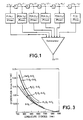
- a transverse filter achieves the summation of samples of a signal, taken at different times, with a law weighting characteristic of the signal to be filtered.
- a filter we seek to determine, for example, the date of appearance of a signal p (t), known a priori.
- Such filter if it maximizes the signal to noise ratio at time T, is said to be suitable.
- the weighting method described for example in the document J. MAX “Methods and techniques of signal processing and applications to physical measurements", Masson, 1987 is an exemplary embodiment of such a filter.
- the signal x (t) feeds a delay line consisting of N elements, each providing a delay T.
- N + 1 points of the signal p (t) p (0), p ( ⁇ ), ... p (N ⁇ ).
- the invention relates to a device for obtaining a large number of samples on very high frequency signals, typically n ⁇ 1024 from 0 to 20 GHz.
- C (t o ) 1 b ⁇ T R (t - t o ) S (t) dt or R (tt 0 ) is a suitably delayed reference signal S (t) is the signal to correlate T is the integration time b is the noise power density per Hz.
- This calculation is to determine the value of t 0 which ensures the maximum of the correlation function C (t 0 ). It is thus necessary to have a large number of samples of the reference signal delayed by different values of t 0 in order to ensure with precision the determination of t 0 which maximizes C (t 0 ).
- Such a function can be performed in electronics but it is limited to signals whose frequency and bandwidth do not exceed a few 100 MHz. This limitation is due to the samples being too slow and the memory capacities too low.
- Fiber optic devices performing correlation two optically transported signals have already been proposed (see par example French Patent Applications n ° 87 10120 and n ° 91 112040).
- document GB 2 189 028 describes a filter comprising in series a multiwavelength optical source, a modulator electrooptics of the multiwavelength beam, a dispersive fiber, an angularly dispersive network and a mechanical filter filtering the result optical processing.
- This device includes in series a laser L, an electrooptical modulator MOD, an optical fiber F, a dispersive network H or dispersive device for wavelengths, a SLM spatial light modulator, a lens (LE), a PD photodetector.
- the laser L provides a beam B1 multi-wavelength ⁇ 1 , ... ⁇ N. It is for example, a solid state laser pumped diode delivering a continuous broadband spectrum or a large set of longitudinal modes. This beam is coupled in the MOD modulator.
- each wavelength ⁇ 1 to ⁇ N can be considered as a carrier independent of the signal x (t).
- the B2 beam from the MOD modulator is coupled in the optical fiber monomode F, used in a spectral range where it is dispersive, that is to say where the refractive index n of the fiber depends on the wavelength.
- B3 beam from the optical fiber F has the different wavelengths delivered by source L all modulated by the MOD modulator, but these different lengths waves experience different delays when crossing the fiber due to the different refractive index n for each wavelength.
- the beam B3 then meets the dispersive network H, operating by example in transmission.
- the latter spatially separates the different wavelength components of the optical carrier.
- Each component then passes through an element of the spatial light modulator SLM.
- the transmission of each modulator element is variable depending on the voltage applied to it and thus allows to apply to each component the desired weighting.
- An LE optical system then performs the summation of all the components, on a single photodetector PD.
- the photodiode PD delivers a photocurrent proportional to the sum:
- the first term Y 0 is a constant bias while the second Y 1 (t 0 ) is the result of the adapted filtering of x (t).
- Such a length of fiber at these wavelengths, introduces losses optical transmission of the order of 8dB (2dB / km).
- the optical fiber is no longer used as a medium dispersive. On the contrary, it is used at a wavelength for which the dispersion is minimal.
- Bragg gratings tuned to wavelengths ⁇ 1 , ⁇ 2 ... ⁇ N , working in reflection are photoinduced in the fiber. Bragg's agreement at different wavelengths is obtained by varying the period of the photoinduced grating.
- the registration method is analogous to that described for example in the document G. Meltz, WW Morey, WH Glenn "Formation of Bragg gratings in optical fibers by a transverse holographic method" Opt. Lett., 14, 823 (1989) and uses a UV laser, ensuring the permanence of the networks.
- the laser source L emits an extended spectrum ⁇ , containing wavelengths ⁇ 1 ... ⁇ N.
- the beam B1 which results therefrom is linearly polarized. It is then coupled in the MOD modulator identical to that previously described, excited by the hyper x (t) signal to be filtered.
- This multifrequency optical carrier is then coupled in the network fiber, where each component will undergo reflection at a different abscissa. This fiber is polarization maintaining in order to be able to easily separate the incident and reflected beams.
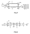
- FIG. 8 represents another alternative embodiment in which, when the divergence of the multifrequency beam B4 is too great compared to at the pixel size of the SLM modulator or when you want a very compact, it is advantageous to use the symmetrical system of the figure 8.
- L c and L ' c are symmetrical lenses, for example with the same focal length.
- H and H ' are similar networks. All the wavelengths are thus recombined in a single direction before being summed by means of the output lens.
- the SLM pixels have the dimensions of the light lines formed by L c .
- the spherical output lens and the detector single of FIG. 8 are replaced respectively by a cylindrical lens, parallel to Lc, and by an array of photodiodes.
- SLM becomes a two-dimensional spatial light modulator (Nxp pixels). Each line of SLM has q independently addressable pixels. Each pixel is associated with a element of the photodiodes array. The system thus allows in parallel perform the filtering adapted to q different signals that may be contained in the signal x (t).
- the device of the invention is also applicable to a correlator of electrical signals (microwave in particular).
- the device for CCD optical detection can include as many elementary detectors as there are of image elements and that these detectors are coupled to a device for transferring charges.
- the role of this device is to correlate two electrical signals S (t) and R (t).
- the first MOD1 electrooptical modulator uses the signal S (t) to modulate the beam B1.
- the second MOD2 electrooptical modulator uses the signal R (t) to modulate the beam B3 coming from the fiber F.
- the beam B3 is, as we have seen previously, made up of a plurality of elementary beams of different optical wavelengths and having suffered different delays in the optical fiber F.
- the MOD2 modulator applies therefore a modulation to each of these elementary beams. So that comes down to this that each of these elementary beams has an amplitude proportional to the produces modulations S (t) and R (t), carried out at different times for each of these elementary beams.
- the dispersive network H spatially distributes the components of the beam B'3 each corresponding to a wavelength (or a narrow range of wavelengths).
- the different elementary beams of the beam B4 are modulated by the SLM spatial light modulator and then transmitted to CCD photodetectors.
- the role of the SLM modulator is to correct the dispersions of source L as well as the transmission system (fibers in particular).
- the SLM modulator may not exist and this correction can be made at the level of detection on the CCD detector or at the level processing the signal detected by the CCD.
- This device provides the same advantages as devices 2 and 4 and allows optically inconsistent detection on each CCD element.
- FIG. 6 represents an alternative embodiment of the correlator of the invention.
- the laser L emitting on a broad spectrum ⁇ , is coupled to two modulators MOD1 and MOD2 such as those described above ( ⁇ F ⁇ 20 GHz). They are respectively excited by the signals S (t) and R (t).
- the beams from these modulators are linearly polarized and pass through polarization splitters or cube polarization splitters PBS 1 and PBS 2 . They are then coupled into two optical fibers F1, F2 with polarization maintenance of the same length 1 where networks have been photoinduced identical to those previously described.
- the networks are arranged so as to reflect successively ⁇ 1 then ⁇ 2 , ... ⁇ N. The order is reversed in fiber F2.
- the different components of the optical carriers S (t) and R (t) pass through the ⁇ / 4 plates and are perfectly reflected by PBS 1 and PBS 2 .
- the beam reflected by the fiber F1 undergoes a polarization rotation of 90 ° and passes through PBS 2 .
- the carriers of the signals R (t) and S (t) are superimposed at the end of PBS 2 and their polarizations are crossed.
- This doubled beam then passes through a dispersive network H where the different wavelengths are spatially dispersed.
- Each of them passes through a first spatial light modulator SLM 1 .
- the latter is, for example, a liquid crystal cell operating in electrically controlled birefringence.
- the polarization coincides for example with the optical axis of the liquid crystal molecules.
- the refractive index seen by this polarization varies, depending on the voltage applied to the pixel, between n 0 and n e (ordinary and extraordinary indices of the liquid crystal).
- the polarization sees a constant refractive index n0.
- SLM 1 therefore makes it possible to control the relative phase shift ⁇ of the carriers of S (t) and R (t).
- a polarizer P oriented at 45 ° from the othogonal polarization directions allows the recombination of these two polarizations.
- a second SLM 2 spatial modulator attached to the first and having the same number of pixels, makes it possible to control the weights ⁇ k assigned to each wavelength component channel.
- an optical system makes it possible to focus each channel on one of the elements of a multiple PDA photodetector, for example of the CCD type.
- each pixel of the CCD delivers a signal proportional to the correlation product S (t) * R (t).
- the photocurrent delivered by the photodetector l is proportional to:
- the total bandwidth of the system is ⁇ F.
- Number of correlation signal samples or channels is N.
- a CCD pixel for an integration time of 1 ms allows the detection of 1 pW, i.e. a detectivity of the order of 3.10 -2 pW / Hz 1/2
- T the NEP ( noise equivalent power) which corresponds to the smallest detectable power, therefore becomes:
- CIP 3.10 -14 ⁇ 1/2
- Figure 7 shows an alternative embodiment of Figure 6.
- the fiber F1 has a chromatic dispersion over a range of optical wavelength ⁇ .
- the F2 fiber is almost free of dispersion.
- the PBS1 device located at the output of the fiber F1 is in fact a device reflection.
- the PBS2 device located at the output of the F2 fiber makes it possible to combine the bundles from fibers F1 and F2.
- the SP device located at the inputs of the fibers F1, F2 is a polarization splitter.
- the beams transmitted to the fibers F1, F2 could also be of same direction of polarization and the SP device could be a separator of light.
- the superimposed bundles from fibers F1, F2 are transmitted by the dispersive network H and the spatial light modulators SLM1 and SLM2 to the CCD optical detection device.
- the product on each CCD detector thus has: that is to say
- the single laser source L is replaced after a set of p sources each emitting a spectrum ⁇ / p.
- a px1 coupler to combine the p sources into a single pigtail connected to the modulator mod.
- N 1024 use 64 semiconductor lasers of a few mW, each emitting 16 modes longitudinal 0.1 nm apart.
Landscapes
- Physics & Mathematics (AREA)
- Engineering & Computer Science (AREA)
- Theoretical Computer Science (AREA)
- Mathematical Physics (AREA)
- Nonlinear Science (AREA)
- Optics & Photonics (AREA)
- General Physics & Mathematics (AREA)
- Optical Communication System (AREA)
- Light Guides In General And Applications Therefor (AREA)
Claims (12)
- Vorrichtung zur optischen Verarbeitung elektrischer Signale, mit :dadurch gekennzeichnet, daß sie außerdem einen rekonfigurierbaren räumlichen Lichtmodulator (SLM) enthält, der mehrere Modulationselemente umfaßt, die das gestreute Strahlenbündel (B4) empfangen und den Lichtstärkepegel für die verschiedenen Richtungen des gestreuten Strahlenbündels (B4) steuern, und daß die Faser (F) Bragg-Gitter enthält, wovon jedes eine bestimmte Schrittweite hat, derart, daß das Licht mit einer bestimmten Wellenlänge reflektiert wird; und daß die Vorrichtung außerdem zwischen dem Modulator (MOD) und der Lichtleitfaser (F) einen Strahlenbündeltrenner (PBS) enthält, der ermöglicht, das von den Bragg-Gittern reflektierte Licht an das Streugitter (H) zu übertragen.einer Lichtquelle (L), die ein Mehrwellenlängen-Lichtstrahlenbündel (B1) aussendet;wenigstens einem ersten elektrooptischen Modulator (MOD), der das Lichtstrahlenbündel (B1) empfängt und es mit Hilfe eines ersten zu verarbeitenden elektrischen Signals moduliert, um ein erstes moduliertes Strahlenbündel auszugeben;wenigstens einer ersten Lichtleitfaser (F), die das modulierte Strahlenbündel (B2) empfängt und Mittel zur räumlichen Trennung enthält, die die Übertragung eines Strahlenbündels (B3) ermöglichen, in dem die den verschiedenen Wellenlängen entsprechenden Komponenten in der Faser (F) relativ zueinander verzögert sind;einem Streugitter (H), das die verschiedenen Wellenlängen, die in dem von der Lichtleitfaser (F) empfangenen Strahlenbündel (B3) enthalten sind, trennt und ein gestreutes Strahlenbündel (B4) ausgibt, in dem jede Wellenlänge in eine für sie charakteristische Richtung abgelenkt wird;
- Vorrichtung nach Anspruch 1, dadurch gekennzeichnet, daß sie zwischen dem räumlichen Lichtmodulator (SLM) und dem optischen Erfassungssystem (PD) eine Fokussierungsvorrichtung enthält, um das Strahlenbündel (B5), das vom Modulator (SLM) verarbeitet wird, auf das optische Erfassungssystem (PD) zu fokussieren.
- Vorrichtung nach Anspruch 1, dadurch gekennzeichnet, daß die Lichtleitfaser (F) eine dispersive Lichtleitfaser ist.
- Vorrichtung nach Anspruch 1, dadurch gekennzeichnet, daß das vom Modulator (MOD) übertragene Licht in einer Richtung polarisiert ist und daß die Vorrichtung zwischen dem Strahlenbündeltrenner (PBS) und der Lichtleitfaser (F) ein Viertelwellenlängenplättchen enthält, wobei der Strahlenbündeltrenner dann ein Polarisationstrenner ist.
- Vorrichtung nach Anspruch 1, dadurch gekennzeichnet, daß das optische Erfassungssystem (PD) ein optischer Photodetektor ist und daß die Vorrichtung eine Fokussierungsvorrichtung enthält, die sich zwischen den räumlichen Lichtmodulator (SLM) und dem optischen Erfassungssystem befindet.
- Vorrichtung nach Anspruch 1, dadurch gekennzeichnet, daß es zwischen dem Streugitter (H) und dem räumlichen Lichtmodulator (SLM) eine Zylinderlinse (Lc) sowie eine zur ersten Zylinderlinse in bezug auf den räumlichen Modulator (SLM) symmetrische Zylinderlinse (L'c) und ein zweites Streugitter (H'), das in bezug auf den räumlichen Modulator (SLM) zum ersten Streugitter symmetrisch ist, enthält.
- Vorrichtung nach Anspruch 6, dadurch gekennzeichnet, daß das optische Erfassungssystem (PD) eine Zeile aus Photodetektoren ist und das die Vorrichtung eine Zylinderlinse enthält, die zwischen dem räumlichen Lichtmodulator und dem optischen Erfassungssystem (PD) enthalten ist.
- Vorrichtung nach Anspruch 1, dadurch gekennzeichnet, daß sie einen zweiten elektrooptischen Modulator (MOD2) enthält, der ebenfalls das Mehrwellenlängen-Lichtstrahlenbündel empfängt und es mit Hilfe eines zweiten zu verarbeitenden elektrischen Signals moduliert, um ein zweites moduliertes Strahlenbündel auszugeben, wobei dieses zweite modulierte Strahlenbündel dem ersten modulierten Strahlenbündel vor der Übertragung an das Streugitter überlagert wird.
- Vorrichtung nach Anspruch 8, dadurch gekennzeichnet, daß sich der zweite elektrooptische Modulator (MOD2) zwischen der Lichtleitfaser (F) und dem Streugitter (H) befindet.
- Vorrichtung nach Anspruch 8, dadurch gekennzeichnet, daß der zweite elektrooptische Modulator (MOD2) parallel zum ersten elektrooptischen Modulator (MOD1) das Mehrwellenlängen-Lichtstrahlenbündel empfängt und es an eine zweite Lichtleitfaser überträgt, die ebenfalls Mittel enthält, die die unterschiedliche Verzögerung der verschiedenen Wellenlängen ermöglicht; wobei die von den beiden Lichtleitfasern ausgegebenen Strahlenbündel an ein Kopplungssystem (PBS1, PBS2) übertragen werden, das sie kombiniert und an das Streugitter überträgt.
- Vorrichtung nach Anspruch 10, dadurch gekennzeichnet, daß die beiden Lichtleitfasern Bragg-Gitter enthalten, wovon jedes eine bestimmte Schrittweite besitzt, derart, daß das Licht mit einer bestimmten Wellenlänge reflektiert wird; und daß die Vorrichtung außerdem die Modulatoren (MOD1, MOD2), die Lichtleitfasern (F1, F2) und die Strahlenbündeltrenner (PBS1, PBS2) enthält, die die Übertragung des von den Bragg-Gittern reflektierten Lichts an das Streugitter ermöglichen.
- Vorrichtung nach Anspruch 11, dadurch gekennzeichnet, daß das von den Modulatoren (MOD1, MOD2) übertragene Licht in einer Richtung polarisiert wird und daß die Vorrichtung ein Viertelwellenlängenplättchen enthält, das sich zwischen den Strahlenbündeltrennern (PBS1, PBS2) und den Fasern (Fl, F2) befindet, wobei die Strahlenbündeltrenner (PBS1, PBS2) dann Polarisationstrenner sind.
Applications Claiming Priority (2)
| Application Number | Priority Date | Filing Date | Title |
|---|---|---|---|
| FR9215085A FR2699295B1 (fr) | 1992-12-15 | 1992-12-15 | Dispositif de traitement optique de signaux électriques. |
| FR9215085 | 1992-12-15 |
Publications (2)
| Publication Number | Publication Date |
|---|---|
| EP0603036A1 EP0603036A1 (de) | 1994-06-22 |
| EP0603036B1 true EP0603036B1 (de) | 1999-07-28 |
Family
ID=9436597
Family Applications (1)
| Application Number | Title | Priority Date | Filing Date |
|---|---|---|---|
| EP93402985A Expired - Lifetime EP0603036B1 (de) | 1992-12-15 | 1993-12-10 | Optische Verarbeitungsvorrichtung für elektrische Signale |
Country Status (4)
| Country | Link |
|---|---|
| US (1) | US5428697A (de) |
| EP (1) | EP0603036B1 (de) |
| DE (1) | DE69325784T2 (de) |
| FR (1) | FR2699295B1 (de) |
Families Citing this family (28)
| Publication number | Priority date | Publication date | Assignee | Title |
|---|---|---|---|---|
| FR2722007B1 (fr) * | 1994-07-01 | 1996-08-23 | Thomson Csf | Filtre transverse et application a un correlatuer optique de signaux electriques |
| US5936484A (en) * | 1995-02-24 | 1999-08-10 | Thomson-Csf | UHF phase shifter and application to an array antenna |
| FR2732783B1 (fr) * | 1995-04-07 | 1997-05-16 | Thomson Csf | Dispositif compact de retroprojection |
| US5859945A (en) * | 1996-04-01 | 1999-01-12 | Sumitomo Electric Industries, Ltd. | Array type light emitting element module and manufacturing method therefor |
| US5754718A (en) * | 1996-08-26 | 1998-05-19 | Jds Fitel Inc. | Hybrid optical filtering circuit |
| FR2755516B1 (fr) | 1996-11-05 | 1999-01-22 | Thomson Csf | Dispositif compact d'illumination |
| US5943453A (en) * | 1997-03-14 | 1999-08-24 | The Board Of Trustees Of The Leland Stanford Junior University | All fiber polarization splitting switch |
| GB9712020D0 (en) * | 1997-06-09 | 1997-08-06 | Northern Telecom Ltd | Equalisation, pulse shaping and regeneration of optical signals |
| JP3913856B2 (ja) * | 1997-08-28 | 2007-05-09 | 富士通株式会社 | 光パルス生成装置、分散測定装置、分散補償装置及び分散測定方法 |
| FR2769154B1 (fr) * | 1997-09-30 | 1999-12-03 | Thomson Csf | Dispositif de synchronisation precise |
| US6016371A (en) * | 1997-12-19 | 2000-01-18 | Trw Inc. | Optical RF signal processing |
| FR2779579B1 (fr) | 1998-06-09 | 2000-08-25 | Thomson Csf | Dispositif de commande optique pour l'emission et la reception d'un radar large bande |
| AU3927900A (en) * | 1999-03-29 | 2000-10-16 | T Squared G Incorporated | Optical digital waveform generator |
| US6607313B1 (en) * | 1999-06-23 | 2003-08-19 | Jds Fitel Inc. | Micro-optic delay element for use in a polarization multiplexed system |
| US6819872B2 (en) | 1999-06-23 | 2004-11-16 | Jds Uniphase Corporation | Micro-optic delay element for use in a time division multiplexed system |
| AU2001238122A1 (en) | 2000-02-08 | 2001-08-20 | University Of Southern California | Optical compensation for dispersion-induced power fading in optical transmission of double-sideband signals |
| US6434291B1 (en) * | 2000-04-28 | 2002-08-13 | Confluent Photonics Corporations | MEMS-based optical bench |
| FR2819061B1 (fr) * | 2000-12-28 | 2003-04-11 | Thomson Csf | Dispositif de controle de polarisation dans une liaison optique |
| GB0100425D0 (en) * | 2001-01-08 | 2001-02-21 | Elettronica Systems Ltd | Apparatus for generating electrical signals with ultra-wide band arbitrary waveforms |
| US20040208646A1 (en) * | 2002-01-18 | 2004-10-21 | Seemant Choudhary | System and method for multi-level phase modulated communication |
| CA2481655C (en) * | 2002-04-09 | 2010-06-15 | Telecom Italia S.P.A. | Apparatus and method for measuring chromatic dispersion by variable wavelength |
| FR2860291B1 (fr) * | 2003-09-26 | 2005-11-18 | Thales Sa | Dispositif capteur de vitesse de rotation interferometrique a fibre optique |
| US7269312B2 (en) * | 2003-11-03 | 2007-09-11 | Hrl Laboratories, Llc | Bipolar RF-photonic transversal filter with dynamically reconfigurable passbands |
| US7233261B2 (en) * | 2004-09-24 | 2007-06-19 | The Curators Of The University Of Missouri | Microwave frequency electro-optical beam deflector and analog to digital conversion |
| FR2880204B1 (fr) * | 2004-12-23 | 2007-02-09 | Thales Sa | Source laser a recombinaison coherente de faisceaux |
| FR2887082B1 (fr) * | 2005-06-10 | 2009-04-17 | Thales Sa | Laser a semi-conducteur a tres faible bruit |
| GB2432946B (en) * | 2005-12-01 | 2010-10-20 | Filtronic Plc | A method and device for generating an electrical signal with a wideband arbitrary waveform |
| FR2945348B1 (fr) | 2009-05-07 | 2011-05-13 | Thales Sa | Procede d'identification d'une scene a partir d'images polarisees multi longueurs d'onde |
Family Cites Families (7)
| Publication number | Priority date | Publication date | Assignee | Title |
|---|---|---|---|---|
| GB8512963D0 (en) * | 1985-05-22 | 1985-06-26 | Marconi Co Ltd | Optical signal processor |
| GB2189028B (en) * | 1986-04-14 | 1990-02-14 | Marconi Co Ltd | Optical analyser and signal processor |
| IT1238535B (it) * | 1989-11-14 | 1993-08-18 | Cselt Centro Studi Lab Telecom | Sistema di comunicazione coerente in fibra ottica a diversita' di polarizzazione in trasmissione |
| US5007705A (en) * | 1989-12-26 | 1991-04-16 | United Technologies Corporation | Variable optical fiber Bragg filter arrangement |
| JP2767996B2 (ja) * | 1990-08-31 | 1998-06-25 | 松下電器産業株式会社 | 対数極座標変換方法および視覚認識方法および光学的情報処理装置 |
| US5136666A (en) * | 1991-08-06 | 1992-08-04 | The University Of Colorado Foundation, Inc. | Fiber optic communication method and apparatus providing mode multiplexing and holographic demultiplexing |
| US5206924A (en) * | 1992-01-31 | 1993-04-27 | The United States Of America As Represented By The Secretary Of The Navy | Fiber optic Michelson sensor and arrays with passive elimination of polarization fading and source feedback isolation |
-
1992
- 1992-12-15 FR FR9215085A patent/FR2699295B1/fr not_active Expired - Fee Related
-
1993
- 1993-12-10 EP EP93402985A patent/EP0603036B1/de not_active Expired - Lifetime
- 1993-12-10 DE DE69325784T patent/DE69325784T2/de not_active Expired - Lifetime
- 1993-12-15 US US08/166,885 patent/US5428697A/en not_active Expired - Fee Related
Non-Patent Citations (1)
| Title |
|---|
| Journal of the Optical Society of America A, 9 (1992), July, No.7, pp.1159-1166. J. Rosen et al.: "Electro-optic hologram generation on spatial light modulators". * |
Also Published As
| Publication number | Publication date |
|---|---|
| DE69325784T2 (de) | 2000-03-09 |
| EP0603036A1 (de) | 1994-06-22 |
| FR2699295A1 (fr) | 1994-06-17 |
| DE69325784D1 (de) | 1999-09-02 |
| US5428697A (en) | 1995-06-27 |
| FR2699295B1 (fr) | 1995-01-06 |
Similar Documents
| Publication | Publication Date | Title |
|---|---|---|
| EP0603036B1 (de) | Optische Verarbeitungsvorrichtung für elektrische Signale | |
| EP0531499B1 (de) | Optisch arbeitender elektrischer transversaler filter | |
| EP0853395B1 (de) | Vorrichtung zur Polarisationsdispersionskompensation in einem optischen Übertragungssystem | |
| EP0882251B1 (de) | Lichtimpulskontrolle mittels programmierbarer akustooptischer vorrichtung | |
| EP0275768B1 (de) | Verstärkungsvorrichtung für optische Signale mit lichtempfindlichem Medium | |
| FR2715524A1 (fr) | Système de communication de type soliton optique ainsi qu'émetteur et récepteur optiques pour ce système. | |
| FR2772150A1 (fr) | Modulateur optique utilisant un isolateur et transmetteur optique comprenant le susdit | |
| FR2754895A1 (fr) | Compteur de voie de signal optique et dispositif d'amplification optique utilisant ce dernier | |
| EP3672109A1 (de) | Vorrichtung und system zur kohärenten rekombination von optischen fasern mit mehreren wellenlängen | |
| FR2810750A1 (fr) | Dispositif acousto-optique programmable pour le controle de l'amplitude du spectre en longueurs d'onde des systemes de communications optiques multiplexes en longueurs d'onde | |
| EP0716486A1 (de) | Wellenlängenkonvertor | |
| EP0505235A1 (de) | Breitbandinterkorrelationsverfahren und Vorrichtung | |
| EP1738444A1 (de) | Einrichtung zur frequenzverschiebung in einem optischen feld mit einer gepulsten laserquelle | |
| FR2728678A1 (fr) | Capteur du type modulation optique et appareil d'instrumentation de processus utilisant celui-ci | |
| FR2857159A1 (fr) | Photodetecteur a cavite verticale resonnante, matrice et systeme de telecommunication correspondant. | |
| EP1723705B1 (de) | Einrichtung zur frequenzverschiebung in einem optischen weg mit einer kontinuierlichen laserquelle | |
| EP3200363B1 (de) | System zur linearen optischen abtastung und kohärenten erkennung eines optischen signals | |
| EP0094866A1 (de) | Gerät für busartige wechselseitige Verbindung mit monomoden Lichtwellenleitern | |
| FR2832227A1 (fr) | Egaliseur spectral dynamique mettant en oeuvre un miroir holographique semi-transparent programmable | |
| EP3935760A2 (de) | Vorrichtung zur kohärenten detektion auf vereinfachte weise und ohne optischen verlust | |
| EP0975106A1 (de) | Anordnung zum Inline-Regenerieren eines optischen Solitonsignals durch synchrone Modulation dieser Solitonen und Übertragungssystem mit einer derartigen Vorrichtung | |
| FR2688324A1 (fr) | Dispositif de detection optronique a amplification optique et son application a la telemetrie et a l'ecartometrie. | |
| FR3155994A1 (fr) | Procede et dispositif de communication-bidirectionnelle sur une seule fibre optique avec une seule source de lumiere | |
| FR2722007A1 (fr) | Filtre transverse et application a un correlatuer optique de signaux electriques | |
| FR2827678A1 (fr) | Attenuateur optique multicanal pour signal multiplexe |
Legal Events
| Date | Code | Title | Description |
|---|---|---|---|
| PUAI | Public reference made under article 153(3) epc to a published international application that has entered the european phase |
Free format text: ORIGINAL CODE: 0009012 |
|
| AK | Designated contracting states |
Kind code of ref document: A1 Designated state(s): DE GB IT |
|
| 17P | Request for examination filed |
Effective date: 19941209 |
|
| 17Q | First examination report despatched |
Effective date: 19970902 |
|
| GRAG | Despatch of communication of intention to grant |
Free format text: ORIGINAL CODE: EPIDOS AGRA |
|
| GRAG | Despatch of communication of intention to grant |
Free format text: ORIGINAL CODE: EPIDOS AGRA |
|
| GRAG | Despatch of communication of intention to grant |
Free format text: ORIGINAL CODE: EPIDOS AGRA |
|
| GRAH | Despatch of communication of intention to grant a patent |
Free format text: ORIGINAL CODE: EPIDOS IGRA |
|
| GRAH | Despatch of communication of intention to grant a patent |
Free format text: ORIGINAL CODE: EPIDOS IGRA |
|
| GRAA | (expected) grant |
Free format text: ORIGINAL CODE: 0009210 |
|
| AK | Designated contracting states |
Kind code of ref document: B1 Designated state(s): DE GB IT |
|
| REF | Corresponds to: |
Ref document number: 69325784 Country of ref document: DE Date of ref document: 19990902 |
|
| ITF | It: translation for a ep patent filed | ||
| PLBE | No opposition filed within time limit |
Free format text: ORIGINAL CODE: 0009261 |
|
| 26N | No opposition filed | ||
| REG | Reference to a national code |
Ref country code: GB Ref legal event code: IF02 |
|
| PGFP | Annual fee paid to national office [announced via postgrant information from national office to epo] |
Ref country code: IT Payment date: 20101218 Year of fee payment: 18 Ref country code: GB Payment date: 20101208 Year of fee payment: 18 |
|
| PGFP | Annual fee paid to national office [announced via postgrant information from national office to epo] |
Ref country code: DE Payment date: 20101208 Year of fee payment: 18 |
|
| GBPC | Gb: european patent ceased through non-payment of renewal fee |
Effective date: 20111210 |
|
| REG | Reference to a national code |
Ref country code: DE Ref legal event code: R119 Ref document number: 69325784 Country of ref document: DE Effective date: 20120703 |
|
| PG25 | Lapsed in a contracting state [announced via postgrant information from national office to epo] |
Ref country code: GB Free format text: LAPSE BECAUSE OF NON-PAYMENT OF DUE FEES Effective date: 20111210 Ref country code: DE Free format text: LAPSE BECAUSE OF NON-PAYMENT OF DUE FEES Effective date: 20120703 |
|
| PG25 | Lapsed in a contracting state [announced via postgrant information from national office to epo] |
Ref country code: IT Free format text: LAPSE BECAUSE OF NON-PAYMENT OF DUE FEES Effective date: 20111210 |