EP0975106A1 - Anordnung zum Inline-Regenerieren eines optischen Solitonsignals durch synchrone Modulation dieser Solitonen und Übertragungssystem mit einer derartigen Vorrichtung - Google Patents
Anordnung zum Inline-Regenerieren eines optischen Solitonsignals durch synchrone Modulation dieser Solitonen und Übertragungssystem mit einer derartigen Vorrichtung Download PDFInfo
- Publication number
- EP0975106A1 EP0975106A1 EP99401395A EP99401395A EP0975106A1 EP 0975106 A1 EP0975106 A1 EP 0975106A1 EP 99401395 A EP99401395 A EP 99401395A EP 99401395 A EP99401395 A EP 99401395A EP 0975106 A1 EP0975106 A1 EP 0975106A1
- Authority
- EP
- European Patent Office
- Prior art keywords
- optical
- signal
- solitons
- clock
- mod
- Prior art date
- Legal status (The legal status is an assumption and is not a legal conclusion. Google has not performed a legal analysis and makes no representation as to the accuracy of the status listed.)
- Granted
Links
- 230000003287 optical effect Effects 0.000 title claims abstract description 113
- 230000008929 regeneration Effects 0.000 title claims abstract description 47
- 238000011069 regeneration method Methods 0.000 title claims abstract description 47
- 230000001360 synchronised effect Effects 0.000 title claims abstract description 12
- 230000005540 biological transmission Effects 0.000 title claims description 27
- 239000004065 semiconductor Substances 0.000 claims abstract description 35
- 239000000835 fiber Substances 0.000 claims description 26
- 238000011084 recovery Methods 0.000 claims description 14
- 238000001914 filtration Methods 0.000 claims description 13
- 230000003321 amplification Effects 0.000 claims description 11
- 238000003199 nucleic acid amplification method Methods 0.000 claims description 11
- 238000011144 upstream manufacturing Methods 0.000 claims description 11
- 230000005693 optoelectronics Effects 0.000 claims description 6
- 239000013307 optical fiber Substances 0.000 claims description 5
- 230000010287 polarization Effects 0.000 claims description 5
- 230000026683 transduction Effects 0.000 claims description 4
- 238000010361 transduction Methods 0.000 claims description 4
- 230000008054 signal transmission Effects 0.000 claims 2
- 230000000903 blocking effect Effects 0.000 description 5
- 230000003595 spectral effect Effects 0.000 description 5
- 238000004088 simulation Methods 0.000 description 4
- 230000008878 coupling Effects 0.000 description 3
- 238000010168 coupling process Methods 0.000 description 3
- 238000005859 coupling reaction Methods 0.000 description 3
- 230000018109 developmental process Effects 0.000 description 3
- 230000001902 propagating effect Effects 0.000 description 3
- 238000009825 accumulation Methods 0.000 description 2
- 239000006185 dispersion Substances 0.000 description 2
- 238000000605 extraction Methods 0.000 description 2
- 230000010363 phase shift Effects 0.000 description 2
- 230000002123 temporal effect Effects 0.000 description 2
- 229910052691 Erbium Inorganic materials 0.000 description 1
- 229910013553 LiNO Inorganic materials 0.000 description 1
- 230000009286 beneficial effect Effects 0.000 description 1
- 230000015556 catabolic process Effects 0.000 description 1
- 230000006835 compression Effects 0.000 description 1
- 238000007906 compression Methods 0.000 description 1
- 230000007423 decrease Effects 0.000 description 1
- 238000006731 degradation reaction Methods 0.000 description 1
- 230000000694 effects Effects 0.000 description 1
- 230000005684 electric field Effects 0.000 description 1
- UYAHIZSMUZPPFV-UHFFFAOYSA-N erbium Chemical compound [Er] UYAHIZSMUZPPFV-UHFFFAOYSA-N 0.000 description 1
- 238000004519 manufacturing process Methods 0.000 description 1
- 239000000463 material Substances 0.000 description 1
- 230000003071 parasitic effect Effects 0.000 description 1
- 230000002441 reversible effect Effects 0.000 description 1
- 230000033764 rhythmic process Effects 0.000 description 1
- 238000007493 shaping process Methods 0.000 description 1
- 230000002269 spontaneous effect Effects 0.000 description 1
Images


Classifications
-
- H—ELECTRICITY
- H04—ELECTRIC COMMUNICATION TECHNIQUE
- H04B—TRANSMISSION
- H04B10/00—Transmission systems employing electromagnetic waves other than radio-waves, e.g. infrared, visible or ultraviolet light, or employing corpuscular radiation, e.g. quantum communication
- H04B10/25—Arrangements specific to fibre transmission
- H04B10/2507—Arrangements specific to fibre transmission for the reduction or elimination of distortion or dispersion
- H04B10/25077—Arrangements specific to fibre transmission for the reduction or elimination of distortion or dispersion using soliton propagation
Definitions
- the invention relates to the field of telecommunications over optical fiber, and especially telecommunications over long distances.
- He is known, for very long distance fiber optic links, use a signal of the type "soliton" having particular spectral properties which allow the signal to be propagate on the dispersive fiber without appreciable chromatic dispersion, that is to say that we use the dependence of the refractive index on the intensity of the optical signal to counterbalance the chromatic dispersion and vice versa.
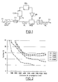
- This regeneration device comprises a MOD modulator controlled by an electrical control signal generated in a clock circuit from the online soliton signal.
- the means for recovering a clock signal comprise an optical coupler C3 for the extraction of a part of the optical signal which propagates between the input F1 and the output F2, a clock extraction circuit CLKX, a delay line DEL to supply a delay and a GM amplifier to supply the power necessary to control the modulator MOD produced for example in LiNO 3 .
- a device polarization control PC birefringent is disposed between the coupler C3 and the modulator MOD, and downstream of the modulator are arranged in series a BP band pass filter to narrow the spectral distribution of the energy of solitons and another birefringent PC polarization control device.
- an EDFA optical amplifier is for example placed in the input fiber F1 as shown in Figure 1, or, alternatively, in the output fiber F2.
- Figure 2 shows a graph showing the result of a numerical simulation intended to show the influences of losses, in particular losses additional, generated by these regeneration devices on the quality of transmission of a soliton signal.
- this simulation we considered a system transmission speed at 20 Gb / s with a 45km spacing between online amplifiers EDFA, and 450km between regeneration devices.
- an online amplifier EDFA is placed downstream of each regeneration device to compensate, at less in part, the losses on the soliton signal due to it.
- the graph shows the quality factor as a function of the transmission distance for regeneration devices respectively generating losses of 0dB, 10dB, 15dB and 20dB.
- the invention aims to propose a regeneration device allowing to modulate the amplitude of solitons in an efficient and precise way, and which does not generate only small additional losses.
- the regeneration device comprises in in addition to means for dividing an optical clock signal, at the output of said means for recovery, in first and second optical clock signals coupled respectively in the first and second arms of said MACH-ZEHNDER modulator for modulate the gains of the first and second semiconductor optical amplifiers respective.
- first and second optical clock signals are respectively coupled downstream of the semiconductor optical amplifiers in the first and second arm of the MACH-ZEHNDER modulator so as to propagate in the direction reverse of the soliton signal to be regenerated, so that subsequent blocking filtering of clock signals is not required.
- first and second signals clock optics are respectively coupled upstream of the optical amplifiers to semiconductor in the first and second arms of the MACH-ZEHNDER modulator so as to propagate in the direction of the signal of solitons to be regenerated.
- means for delaying the first and second optical clock signals and amplitude adjustment means of the first and second optical clock signals are disposed between said dividing means and said semiconductor optical amplifiers.
- said clock recovery means include an optoelectronic unit equipped with transduction means optical / electronic and vice versa, as well as electronic amplification means and filtering and means for shaping electronic signals.
- said clock recovery means include an all-optical unit, free from optical / electronic transduction or vice versa.
- the wavelengths of the first and second optical signals clock modulating the gains of semiconductor optical amplifiers are different from the wavelength of the solitons to be modulated.
- said recovery means of said clock signal comprise an electrical control circuit for gains of the first and second semiconductor optical amplifiers.
- each optical amplifier semiconductor is independent of the polarization of the solitons to be modulated.
- each semiconductor optical amplifier is substantially close to the saturation regime to allow efficient modulation of the soliton signal to be regenerated.
- the regeneration device according to the invention has a total gain in amplification equal to or greater than losses caused by him.
- the device further comprises means for filtering arranged upstream and / or downstream of the MACH-ZEHNDER modulator and allowing to control the spectro-temporal characteristics of the solitons before and / or after modulation.
- the regeneration device as defined above is particularly suitable good for use as a "3R" regenerator.
- the device according to the invention can be used to modulate so independent the amplitude and phase of a soliton signal to be regenerated.
- the invention also relates to a system for transmitting signal solitons by optical fiber, characterized in that it comprises at least one device for regeneration according to the invention as defined above.
- this transmission system comprises in in addition to online filtering means for solitons.
- each optical amplifier of which soliton signals of the transmission system is constituted by a device of regeneration with a total gain of amplification equal to or greater than the losses generated by him.
- the device according to the invention makes it possible not only to regenerate soliton signals but also compensate for all losses, in particular line losses so the transmission system can operate without them classic EDFA online amplifiers.
- the transmission system comprises at least one regeneration device as defined above arranged downstream of a unit for multiplexing signals into a plurality of soliton signals having lengths of different wave and the same clock rate and upstream of a demultiplexing unit corresponding, to ensure synchronous regeneration of soliton signals of different wavelength.
- upstream and downstream as well as “co-propagation” and “counter-propagation” refer to the direction of propagation of the optical signal from solitons to regenerate at the entrance of the device according to the invention.
- Figure 3 is schematically shown a regeneration device in line of an optical signal of solitons by a synchronous modulation of these solitons according to the invention.
- the online regeneration device comprises a modulator MACH-ZEHNDER MOD comprising a first SOA1 and a second SOA2 amplifiers semiconductor optics, preferably identical. These optical amplifiers with semiconductor SOA1 and SOA2 are respectively arranged in a first F5 and a second F6 arm of the MACH-ZEHNDER MOD modulator.
- the semiconductor amplifiers SOA1 and SOA2 are preferably chosen as they amplify the soliton signals regardless of the polarization of these last.
- the device includes means for recovering a clock signal making it possible to extract the clock rate of the bits of the signal to be regenerated.
- These recovery means comprise a coupler C3 whose output is connected by an F4 fiber at the input of a CLK unit for recovering a clock signal.
- the CLK unit comprises an optical output of an optical clock signal of wavelength ⁇ c different from the wavelength ⁇ S of the optical signal of solitons to be regenerated.
- the CLK unit can be achieved by means optoelectronic or by all optical means.
- the optical output of the CLK unit is connected via an F3 fiber to means for dividing DIV 50/50 of this optical clock signal into a first and a second optical clock signal having substantially the same intensity.
- the term 50/50 means that the DIV means divide the optical clock signal into two signals clock optics of substantially equal intensity.
- These DIV division means can for example be formed by a Y-shaped panel.
- the DIV division means include a first and second optical outputs which are respectively connected via respective fibers F_CLK1 and F_CLK2 at the first branch F5 and at the second branch F6 of the MACH-ZEHNDER MOD modulator, downstream of the optical amplifiers semiconductor SOA1 and SOA2.
- This connection of the fibers F_CLK1 and F_CLK2 downstream of the optical semiconductor amplifiers SOA 1 and SOA 2 has the advantage that the optical clock signals propagate in opposite directions from the soliton signals to be regenerated so that in the optical fiber output F2 only circulates the regenerated soliton signal and that a filter blocking the optical clock signals is not necessary.
- the optical clock signals can also be introduced into arms F5 and F6 in co-propagation.
- the fibers F_CLK1 and F_CLK2 are respectively connected to the first branch F5 and to the second branch F6 of the MACH-ZEHNDER MOD modulator, upstream of the amplifiers SOA1 and SOA2 semiconductor optics.
- a filter blocking clock optical signals in co-propagation is provided in the fiber optical output F2.
- a delay line DEL_CLK1 and means A_CLK1 of adjustment of the amplitude of the first optical clock signal constituted for example by a attenuator, are arranged in series in the transmission fiber F_CLK1 in order to be able adjust the delay and amplitude of the first optical clock signal relative to the second.
- a DEL_CLK2 delay line and A_CLK2 means for adjusting the amplitude of the second optical clock signal are arranged in series in the transmission fiber F_CLK2.
- the CLK unit comprises an electrical control circuit for the gains of semiconductor optical amplifiers SOA1 and SOA2 to allow modulation of the amplitude of the solitons by said clock signal.
- BP filtering means are arranged upstream of the modulator MACH-ZEHNDER MOD to allow control of spectro-temporal characteristics solitons before modulation.
- these filtering means can also be arranged downstream of the MACH-ZEHNDER MOD modulator or even be provided upstream and downstream thereof.
- the regeneration device operates as follows.
- the coupler C3 takes a small part of the signal to extract a clock signal by the CLK recovery unit.
- the optical clock signal at the output of the CLK unit is divided into the DIV means into a first and a second optical clock signal propagating respectively in the fibers F_CLK1 and F_CLK2.
- Deadlines and amplitudes optical clock signals are respectively adjusted by the delay lines DEL_CLK1, DEL_CLK2 as well as by the attenuators A_CLK1 and A_CLK2.
- the first clock signal propagating in the fiber F_CLK1 causes the gain modulation of the optical amplifier SOA1, the second optical clock signal propagating in the fiber F_CLK2 that of the optical amplifier SOA2 for modulate the amplitude of the solitons based on the clock signal recovered.
- the phases ⁇ 1 (t) and ⁇ 2 (t) of relations 2 and 3 respectively represent optical phase shifts introduced into the soliton signal respectively during
- P i (t) is the power of the optical clock signal applied to the optical amplifier SOAi.
- the maximum amplitude of P i (t) is between 10 -2 * P sat and 10 2 * P sat , preferably close to the saturation power P sat .
- each SOA1, SOA2 semiconductor optical amplifier operates preferably in a regime close to saturation.
- the regeneration device can be easily adapted to meet modulation requirements intensity and trill function ("CHIRP" in English).
- the regeneration device has the advantage that the amplitude modulation and the phase modulation of the soliton optical signal can be controlled independently of each other, which is very beneficial for the regeneration of solitons.
- each SOA1 semiconductor optical amplifier, SOA2 is chosen high enough for the regeneration device to generate only low losses.
- this gain is even chosen at such a level that it completely compensates for or even exceeds the losses caused by the regeneration so the device is an online regenerator / amplifier of the soliton signal.
- the CLK unit for recovering a clock signal can be either an optoelectronic unit ( Figure 4), or an all-optical unit ( Figure 5).
- FIG 4 schematically shows an example of the CLK optoelectronic unit.
- the optical signal taken by the coupler C3 in Figure 3 propagates on the fiber F4 to a PD photodetector which converts the received optical signal into a signal electronic.
- the electronic signal thus obtained is first amplified by an amplifier AE1 microwave electronics, then in the case of a NRZ signal (no return to zero in English), the signal will be filtered by a first B / 2 bandpass filter.
- the filtered signal is then multiplied in frequency by a frequency doubler X2, and undergoes a second filtering bandpass in filter B.
- filtering by filter B will be the first filtering.
- the signal is then amplified to control an LD diode laser, which emits a light signal to the rhythm of the electronic impulses which are the results optical signals taken from C3.
- This optical clock signal can optionally be amplified by an optical amplifier AO1 before being divided into the means of DIV division of figure 3.
- Figure 5 schematically shows an example of recovery means in which the CLK unit is produced in an entirely optical manner according to the principles of mode blocking of a ring fiber laser.
- the optical signal of the soliton type, taken by the coupler C3 of FIG. 3 is propagates on F4 fiber to a loop of R fiber to which it is coupled via a coupler C7.
- the fiber loop R and the various components found therein a ring laser similar to that described in the article by L.E. Adams et al. "All-optical recovery using a modelocked figure eight laser with a semiconductor non-linearity ", Electronics Letters, Volume 30, N ° 20, pp 1696-1697, Sep 29, 1994.
- the ring laser includes AOL amplification means, an isolator optical I for unidirectional operation, optical filtering means FL centered on the wavelength of the laser light, and optical coupling means nonlinear CONL to obtain amplitude and / or phase nonlinearities as a function of the amplitude of the electric field of the light circulating in the fiber R.
- These non-linear means can for example be a non-linear optical mirror NOLM as described in the aforementioned article by Adams et al.
- the ring laser can operate continuously (CW) in the absence of a signal soliton injected via the C7 coupler.
- CW continuously
- a bit stream is introduced via the coupler C7
- there is an asymmetric non-linear phase shift introduced between components in counter-propagation, an increase in the transmittivity of the optical mirror non-linear, and blocking of the modes of the ring laser at the rate of the bits of the signal.
- These pulses can then be taken via an optical coupler C8 to give a clock signal substantially without time jitter.
- Figure 5 shows a second AOH optical amplifier and C / E compression and / or expansion means, for give the desired shape to the pulses from the ring laser (amplitude, duration, temporal form of ascent and descent, ). Indeed, the raw pulses are relatively narrow, and it may be desirable to widen them before being divided and applied to SOA1 and SOA2 semiconductor optical amplifiers.
- FIG. 6 schematically shows a first example of a system of transmission of soliton signals according to the invention (C3, CLK, MOD) as well as a plurality of online optical amplifiers (G1, G2, G3 ...) and a plurality of filters guides (BP1, BP2, BP3, .).
- the guiding filters compress the spectral width of the solitons, but remove energy from the solitons by doing so.
- the sliding-frequency guiding filter an improved form of soliton jitter control
- the time jitter is also reduced by the guiding filters.
- Figure 7 shows schematically a second example of a system of transmission of soliton signals according to the invention (C3, CLK, MOD).
- This system differs of that of FIG. 6 by the fact that the device according to the invention is adjusted in such a way so that in addition to modulating the soliton signals, it amplifies these signals with a some gain greater than coupling losses and additional losses generated by the device itself. So the transmission system only includes the regeneration devices according to the invention arranged in the transmission fiber at predefined distance intervals, for example 50 km. On the other hand, this system of no other online optical amplifiers such as for example EDFA.
- the regeneration device therefore acts as a regenerator known by the name of "3R regenerator", that is to say a regenerator which readjust the solitons over time (“ R etiming” in English) puts them back in their original envelopes (“ R eshaping” in English) and re-amplifies them (“ R eamplification” in English) at their original amplitude levels.
- the transmission system further comprises a unit for multiplexing signals into a plurality of soliton signals having different wavelengths ⁇ 1 , ⁇ 2 , ⁇ 3 « and the same clock rate and a corresponding demultiplexing unit.
- the regeneration device according to the invention is arranged downstream of the multiplexing unit and upstream of the demultiplexing unit and ensures the synchronous and simultaneous regeneration of the soliton signals of different wavelengths.
Landscapes
- Physics & Mathematics (AREA)
- Electromagnetism (AREA)
- Engineering & Computer Science (AREA)
- Computer Networks & Wireless Communication (AREA)
- Signal Processing (AREA)
- Optical Communication System (AREA)
- Optical Modulation, Optical Deflection, Nonlinear Optics, Optical Demodulation, Optical Logic Elements (AREA)
Applications Claiming Priority (2)
| Application Number | Priority Date | Filing Date | Title |
|---|---|---|---|
| FR9809410A FR2781625B1 (fr) | 1998-07-23 | 1998-07-23 | Dispositif de regeneration en ligne d'un signal optique de solitons par une modulation synchrone de ces solitons et systeme de transmission comportant un tel dispositif |
| FR9809410 | 1998-07-23 |
Publications (2)
| Publication Number | Publication Date |
|---|---|
| EP0975106A1 true EP0975106A1 (de) | 2000-01-26 |
| EP0975106B1 EP0975106B1 (de) | 2001-12-12 |
Family
ID=9528934
Family Applications (1)
| Application Number | Title | Priority Date | Filing Date |
|---|---|---|---|
| EP19990401395 Expired - Lifetime EP0975106B1 (de) | 1998-07-23 | 1999-06-10 | Anordnung zum Inline-Regenerieren eines optischen Solitonsignals durch synchrone Modulation dieser Solitonen und Übertragungssystem mit einer derartigen Vorrichtung |
Country Status (7)
| Country | Link |
|---|---|
| EP (1) | EP0975106B1 (de) |
| JP (1) | JP2000047274A (de) |
| CN (1) | CN1246759A (de) |
| AU (1) | AU4103899A (de) |
| CA (1) | CA2274747A1 (de) |
| DE (1) | DE69900572T2 (de) |
| FR (1) | FR2781625B1 (de) |
Cited By (1)
| Publication number | Priority date | Publication date | Assignee | Title |
|---|---|---|---|---|
| FR2810176A1 (fr) * | 2000-06-09 | 2001-12-14 | Cit Alcatel | Dispositif de regeneration de signaux optiques |
Families Citing this family (4)
| Publication number | Priority date | Publication date | Assignee | Title |
|---|---|---|---|---|
| KR100353845B1 (ko) * | 2000-12-27 | 2002-09-28 | 한국전자통신연구원 | 반도체광증폭기를 이용한 상호위상변조방식의 파장변환장치 및 그 방법 |
| DE60225116T2 (de) | 2002-04-24 | 2009-02-19 | Alcatel Lucent | Remodulator für optische Übertragungssysteme |
| CN100342269C (zh) * | 2003-06-19 | 2007-10-10 | 日本电信电话株式会社 | 光调制装置 |
| CN111983871B (zh) * | 2020-09-03 | 2022-05-20 | 山西大学 | 光孤子脉冲串的全光放大方法 |
-
1998
- 1998-07-23 FR FR9809410A patent/FR2781625B1/fr not_active Expired - Fee Related
-
1999
- 1999-06-10 DE DE1999600572 patent/DE69900572T2/de not_active Expired - Fee Related
- 1999-06-10 EP EP19990401395 patent/EP0975106B1/de not_active Expired - Lifetime
- 1999-06-15 CA CA 2274747 patent/CA2274747A1/fr not_active Abandoned
- 1999-07-08 JP JP11194804A patent/JP2000047274A/ja active Pending
- 1999-07-21 AU AU41038/99A patent/AU4103899A/en not_active Abandoned
- 1999-07-22 CN CN 99110639 patent/CN1246759A/zh active Pending
Non-Patent Citations (3)
| Title |
|---|
| BIGO S ET AL: "ALL-OPTICAL REGENERATOR FOR 20 GBIT/S TRANSOCEANIC TRANSMISSION", ELECTRONICS LETTERS, vol. 33, no. 11, 22 May 1997 (1997-05-22), pages 975/976, XP000727023 * |
| BIGO S ET AL: "ERROR-FREE SOLITON TRANSMISSION AT 20 GBIT/S OVER 7150 KM THROUGH ALL-OPTICAL SYNCHRONOUS PHASE MODULATION", ELECTRONICS LETTERS, vol. 33, no. 6, 13 March 1997 (1997-03-13), pages 449/450, XP000693253 * |
| DURHUUS T ET AL: "MONOLITHIC INTEGRATED MACH-ZEHNDER WAVELENGTH CONVERTER: CONVERSIONAND TRANSMISSION EXPERIMENTS AT 5 GBIT/S", OPTICAL FIBER COMMUNICATION. SUMMARIES OF PAPERS PRESENTED AT THE CONFERENCE OFC '95, SAN DIEGO, FEB. 26 - MAR. 3, 1995, 26 February 1995 (1995-02-26), INSTITUTE OF ELECTRICAL AND ELECTRONICS ENGINEERS, pages 75/76, XP000517654 * |
Cited By (2)
| Publication number | Priority date | Publication date | Assignee | Title |
|---|---|---|---|---|
| FR2810176A1 (fr) * | 2000-06-09 | 2001-12-14 | Cit Alcatel | Dispositif de regeneration de signaux optiques |
| US6807379B2 (en) | 2000-06-09 | 2004-10-19 | Alcatel | Device for regenerating optical signs |
Also Published As
| Publication number | Publication date |
|---|---|
| DE69900572T2 (de) | 2002-08-01 |
| EP0975106B1 (de) | 2001-12-12 |
| JP2000047274A (ja) | 2000-02-18 |
| FR2781625A1 (fr) | 2000-01-28 |
| CA2274747A1 (fr) | 2000-01-23 |
| AU4103899A (en) | 2000-02-17 |
| FR2781625B1 (fr) | 2000-09-08 |
| CN1246759A (zh) | 2000-03-08 |
| DE69900572D1 (de) | 2002-01-24 |
Similar Documents
| Publication | Publication Date | Title |
|---|---|---|
| FR2715524A1 (fr) | Système de communication de type soliton optique ainsi qu'émetteur et récepteur optiques pour ce système. | |
| FR2781321A1 (fr) | Amplification quasi-distribuee dans un systeme de transmission a fibre optique a signaux solitons | |
| EP0862286B1 (de) | Optische Regenerierung für faseroptische Übertragungssysteme mit nicht-Soliton Signalen | |
| EP1162769B1 (de) | Vorrichtung zum Regenerieren optischer Signale | |
| FR2754895A1 (fr) | Compteur de voie de signal optique et dispositif d'amplification optique utilisant ce dernier | |
| CA2238923C (fr) | Systeme de transmission optique a compensation dynamique de la puissance transmise | |
| EP0630123B1 (de) | Einrichtung zur Regenerierung eines Impulszuges und Einrichtung zur Rückgewinnung eines zu einem modulierten Impulszug synchronisierten periodischen Signals | |
| FR2739502A1 (fr) | Amplificateur de lumiere | |
| EP0975106B1 (de) | Anordnung zum Inline-Regenerieren eines optischen Solitonsignals durch synchrone Modulation dieser Solitonen und Übertragungssystem mit einer derartigen Vorrichtung | |
| EP1087553A1 (de) | Optischer Regenerator für WDM Signalen | |
| FR2796766A1 (fr) | Amplificateur optique a pompage bidirectionnel | |
| EP0999622A1 (de) | Optische Halbleiterverstärker mit kontrolierter stabilisierter Verstärkung und optisches System unter Verwendung desselben | |
| FR2751150A1 (fr) | Systeme de transmission optique de donnees en format soliton | |
| EP0901206B1 (de) | Optischer Vorverstärker | |
| FR2950164A1 (fr) | Systeme de controle de polarisation tout-optique a faisceau de pompe contra-propagatif | |
| EP1137208B1 (de) | Synchroner optischer Regenerator unter Verwendung von Intensitätsmodulation und Phasenmodulation mit gekreutzen Kerreffekt | |
| EP0746070B1 (de) | Verfahren und Vorrichtung zur Kombination optischer Signale | |
| EP1158352A2 (de) | Optischer NRZ-RZ-Wandler | |
| CA2259017A1 (fr) | Procede et dispositif de resynchronisation de signaux optiques | |
| FR2784826A1 (fr) | Repeteur pour systeme de transmission a fibre optique de longue portee a multiplexage en longueur d'onde | |
| WO2002019574A1 (fr) | Regenerateur tout-optique pour signaux multiplexes en longueur d'onde | |
| FR2787953A1 (fr) | Amplification quasi-distribuee dans un systeme de transmission a fibre optique | |
| FR2760855A1 (fr) | Regeneration optique pour des systemes de transmission a fibre optique a signaux solitons | |
| EP1372278A1 (de) | Monolithisches Halbleiterbauelement für optische Signalregenerierung | |
| FR2879053A1 (fr) | Dispositif regenerateur 2r/3r tout-optique a base d'un unique modulateur a electroabsorption |
Legal Events
| Date | Code | Title | Description |
|---|---|---|---|
| PUAI | Public reference made under article 153(3) epc to a published international application that has entered the european phase |
Free format text: ORIGINAL CODE: 0009012 |
|
| AK | Designated contracting states |
Kind code of ref document: A1 Designated state(s): DE GB IT |
|
| AX | Request for extension of the european patent |
Free format text: AL;LT;LV;MK;RO;SI |
|
| 17P | Request for examination filed |
Effective date: 20000726 |
|
| AKX | Designation fees paid |
Free format text: DE GB IT |
|
| 17Q | First examination report despatched |
Effective date: 20001110 |
|
| GRAG | Despatch of communication of intention to grant |
Free format text: ORIGINAL CODE: EPIDOS AGRA |
|
| GRAG | Despatch of communication of intention to grant |
Free format text: ORIGINAL CODE: EPIDOS AGRA |
|
| GRAH | Despatch of communication of intention to grant a patent |
Free format text: ORIGINAL CODE: EPIDOS IGRA |
|
| GRAH | Despatch of communication of intention to grant a patent |
Free format text: ORIGINAL CODE: EPIDOS IGRA |
|
| GRAA | (expected) grant |
Free format text: ORIGINAL CODE: 0009210 |
|
| AK | Designated contracting states |
Kind code of ref document: B1 Designated state(s): DE GB IT |
|
| REG | Reference to a national code |
Ref country code: GB Ref legal event code: IF02 |
|
| GBT | Gb: translation of ep patent filed (gb section 77(6)(a)/1977) |
Effective date: 20011212 |
|
| REF | Corresponds to: |
Ref document number: 69900572 Country of ref document: DE Date of ref document: 20020124 |
|
| PLBE | No opposition filed within time limit |
Free format text: ORIGINAL CODE: 0009261 |
|
| STAA | Information on the status of an ep patent application or granted ep patent |
Free format text: STATUS: NO OPPOSITION FILED WITHIN TIME LIMIT |
|
| 26N | No opposition filed | ||
| PGFP | Annual fee paid to national office [announced via postgrant information from national office to epo] |
Ref country code: IT Payment date: 20080624 Year of fee payment: 10 |
|
| PGFP | Annual fee paid to national office [announced via postgrant information from national office to epo] |
Ref country code: DE Payment date: 20080620 Year of fee payment: 10 |
|
| PGFP | Annual fee paid to national office [announced via postgrant information from national office to epo] |
Ref country code: GB Payment date: 20080620 Year of fee payment: 10 |
|
| GBPC | Gb: european patent ceased through non-payment of renewal fee |
Effective date: 20090610 |
|
| PG25 | Lapsed in a contracting state [announced via postgrant information from national office to epo] |
Ref country code: GB Free format text: LAPSE BECAUSE OF NON-PAYMENT OF DUE FEES Effective date: 20090610 |
|
| PG25 | Lapsed in a contracting state [announced via postgrant information from national office to epo] |
Ref country code: DE Free format text: LAPSE BECAUSE OF NON-PAYMENT OF DUE FEES Effective date: 20100101 |
|
| PG25 | Lapsed in a contracting state [announced via postgrant information from national office to epo] |
Ref country code: IT Free format text: LAPSE BECAUSE OF NON-PAYMENT OF DUE FEES Effective date: 20090610 |