EP0603087B1 - Vorhangsbeschichtungs- Verfahren und Vorrichtung - Google Patents
Vorhangsbeschichtungs- Verfahren und Vorrichtung Download PDFInfo
- Publication number
- EP0603087B1 EP0603087B1 EP93420491A EP93420491A EP0603087B1 EP 0603087 B1 EP0603087 B1 EP 0603087B1 EP 93420491 A EP93420491 A EP 93420491A EP 93420491 A EP93420491 A EP 93420491A EP 0603087 B1 EP0603087 B1 EP 0603087B1
- Authority
- EP
- European Patent Office
- Prior art keywords
- curtain
- duct
- liquid
- coating
- lubricating liquid
- Prior art date
- Legal status (The legal status is an assumption and is not a legal conclusion. Google has not performed a legal analysis and makes no representation as to the accuracy of the status listed.)
- Expired - Lifetime
Links
- 238000007766 curtain coating Methods 0.000 title claims description 16
- 238000000034 method Methods 0.000 title claims description 14
- 239000007788 liquid Substances 0.000 claims description 88
- 230000001050 lubricating effect Effects 0.000 claims description 49
- 239000011248 coating agent Substances 0.000 claims description 34
- 238000000576 coating method Methods 0.000 claims description 34
- XLYOFNOQVPJJNP-UHFFFAOYSA-N water Substances O XLYOFNOQVPJJNP-UHFFFAOYSA-N 0.000 claims description 9
- 238000009826 distribution Methods 0.000 claims description 5
- 239000002131 composite material Substances 0.000 claims description 4
- 238000000151 deposition Methods 0.000 claims description 3
- 238000009736 wetting Methods 0.000 claims description 3
- 239000012530 fluid Substances 0.000 description 7
- 238000004519 manufacturing process Methods 0.000 description 5
- 230000008569 process Effects 0.000 description 5
- 238000013461 design Methods 0.000 description 4
- 239000000758 substrate Substances 0.000 description 4
- 230000008859 change Effects 0.000 description 2
- 238000007688 edging Methods 0.000 description 2
- 235000020030 perry Nutrition 0.000 description 2
- 239000000126 substance Substances 0.000 description 2
- 230000007704 transition Effects 0.000 description 2
- 230000004075 alteration Effects 0.000 description 1
- 230000000739 chaotic effect Effects 0.000 description 1
- 230000008602 contraction Effects 0.000 description 1
- 230000001419 dependent effect Effects 0.000 description 1
- 230000000694 effects Effects 0.000 description 1
- 230000008030 elimination Effects 0.000 description 1
- 238000003379 elimination reaction Methods 0.000 description 1
- 238000002474 experimental method Methods 0.000 description 1
- 238000005461 lubrication Methods 0.000 description 1
- 239000000463 material Substances 0.000 description 1
- 239000000203 mixture Substances 0.000 description 1
- 238000012986 modification Methods 0.000 description 1
- 230000004048 modification Effects 0.000 description 1
- 230000009467 reduction Effects 0.000 description 1
- 238000011160 research Methods 0.000 description 1
- 230000006641 stabilisation Effects 0.000 description 1
- 239000002699 waste material Substances 0.000 description 1
Images


Classifications
-
- G—PHYSICS
- G03—PHOTOGRAPHY; CINEMATOGRAPHY; ANALOGOUS TECHNIQUES USING WAVES OTHER THAN OPTICAL WAVES; ELECTROGRAPHY; HOLOGRAPHY
- G03C—PHOTOSENSITIVE MATERIALS FOR PHOTOGRAPHIC PURPOSES; PHOTOGRAPHIC PROCESSES, e.g. CINE, X-RAY, COLOUR, STEREO-PHOTOGRAPHIC PROCESSES; AUXILIARY PROCESSES IN PHOTOGRAPHY
- G03C1/00—Photosensitive materials
- G03C1/74—Applying photosensitive compositions to the base; Drying processes therefor
-
- B—PERFORMING OPERATIONS; TRANSPORTING
- B05—SPRAYING OR ATOMISING IN GENERAL; APPLYING FLUENT MATERIALS TO SURFACES, IN GENERAL
- B05C—APPARATUS FOR APPLYING FLUENT MATERIALS TO SURFACES, IN GENERAL
- B05C5/00—Apparatus in which liquid or other fluent material is projected, poured or allowed to flow on to the surface of the work
- B05C5/007—Slide-hopper coaters, i.e. apparatus in which the liquid or other fluent material flows freely on an inclined surface before contacting the work
- B05C5/008—Slide-hopper curtain coaters
-
- Y—GENERAL TAGGING OF NEW TECHNOLOGICAL DEVELOPMENTS; GENERAL TAGGING OF CROSS-SECTIONAL TECHNOLOGIES SPANNING OVER SEVERAL SECTIONS OF THE IPC; TECHNICAL SUBJECTS COVERED BY FORMER USPC CROSS-REFERENCE ART COLLECTIONS [XRACs] AND DIGESTS
- Y10—TECHNICAL SUBJECTS COVERED BY FORMER USPC
- Y10S—TECHNICAL SUBJECTS COVERED BY FORMER USPC CROSS-REFERENCE ART COLLECTIONS [XRACs] AND DIGESTS
- Y10S118/00—Coating apparatus
- Y10S118/04—Curtain coater
Definitions
- the present invention relates to a method and apparatus for coating objects or moving supports advancing continuously through a coating station with a free-falling curtain of coating liquid. More particularly, the present invention relates to a curtain coating method and apparatus for the manufacture of photographic film and paper.
- a moving support is coated by causing a free falling curtain of coating liquid, referred to hereafter as simply the curtain, to impinge on the moving support to form a layer thereon.
- a free falling curtain of coating liquid referred to hereafter as simply the curtain.
- the quality of the coating is largely determined by the properties of the liquid curtain. It is important to insure that a stable laminar flow of coating solution is formed by the slide hopper and that an equally stable laminar liquid curtain is formed from that coating solution. To prevent contraction of the edges of the falling curtain under the effect of surface tension it is known that the curtain must be guided at its edges by curtain edge guides.
- a lubricating liquid between the curtain and the edge guide will improve the operation of the curtain. These improvements include the ability to maintain the curtain at lower total flow rates with lubricating liquid than without, and the ability to maintain curtains of higher viscosity with a lubricating liquid than without.
- the lubricating liquid is simply water, however, an alternate liquid of low viscosity may be used for the same purpose.
- the momentum of the solutions at the coating point is a critical variable in determining the size of the window of operability of the curtain coating process. If the momentum is low, the maximum coating speed attainable before the onset of air entrainment is reduced. Therefore, for an internal edging process (coating within the edges of a web), the lubricating liquid must be introduced as close to the hopper lip as possible to maximize the momentum of the solution near the edge of the curtain at the coating point. This is to minimize the span the curtain must travel with a non-lubricated wall at the edge. Any velocity which is lost due to wall drag at the edges, with respect to the velocity of the curtain sufficiently far from the edge guides to be unaffected by the velocity drag of the edge guides, cannot be regained.
- the edges of the curtain will have lower momentum than will the middle due to wall drag along the edge guide. This results in a smaller window of operability at the edges of the curtain than in the middle. This limits the maximum speed attainable for the entire curtain. This coating speed reduction due to momentum loss at the edges can have a severe negative impact on the efficiency of a manufacturing operation employing curtain coating.
- WO-A-89/10583 describes a curtain coating method and apparatus using lateral liquid edge guide means in order to maintain the width of the curtain throughout its free fall. Extracting fluid means at the edges and near the bottom of the free fall is also provided.
- EP-A-327020 describes a coating apparatus wherein jets of an auxiliary liquid are provided in the vicinity of the lip to prevent thinning of the curtain film in the vicinity of the edge guides of the apparatus.
- the flow velocity of the liquid edge is increased so that there is no difference in flow velocity between the liquid edge guide and the central portion of the curtain film.
- EP-A-115621 describes a curtain coating apparatus wherein liquid edge guide means are provided. A laminar flow for the liquid layers of the curtain coating is mentioned. An optimal stabilisation of the curtain coating is obtained by adapting viscosity, surface tension and quantity of the liquid delivered to the porous edge guide means.
- Turbulent and laminar flow regimes are generally classified through use of the Reynolds number, Re. This is a dimensionless group of parameters used to relate the inertial forces in a flow to the viscous forces. At high Reynolds numbers turbulence is more likely than at low Reynolds numbers. For different flow geometries, experiments have determined Reynolds number ranges which classify the laminar flow, transition regions and fully turbulent flow region. It is therefore desirable to be operating in the laminar flow region for the specific geometry being used.
- the rate of decay is dependent upon the magnitude of the Reynolds number, the lower the Reynolds number, the quicker disturbances will decay.
- the rate of decay, or length that the flow must continue past the disturbance to be free of turbulence can be estimated by calculating the entry length, L e .
- the entry length is a measure of how much distance the liquid must travel after a disturbance, for example, the inlet of a channel, to form a fully developed laminar flow profile. For tube flow (circular cross-section) this is the distance after the inlet into the tube it takes to develop Poiseuille flow.
- the present invention describes an apparatus and method for optimizing the geometry of the lubricating fluid delivery tube or channel to allow for the outlet to be placed very close to the hopper lip, while avoiding turbulence at the outlet. This results in being able to coat at higher speeds due to an increase in momentum at the edges of the curtain and the elimination of wavy edges and curtain waves due to turbulent flow of the lubricating liquid.
- the present invention as described in claims 1 and 8 concerns a method and apparatus for coating a support by depositing one or more coating liquids onto the moving support.
- the apparatus includes a conveying means including a coating roll for moving the support along a path through a coating zone, hopper means for forming one or more flowing layers of coating liquids to form a composite free-falling curtain which extends transversely of said path and impinges on the moving support, and edge guide means spaced a distance apart for laterally guiding the falling curtain.
- a liquid distributing means for issuing the lubricating liquid from the edge guide means is used to maintain wetting contact with the edge of the falling curtain, the liquid distributing means issues lubricating liquid in the laminar flow region.
- the liquid distributing means comprises a curved duct which has a circular cross-section and the lubricating liquid is water.
- the liquid distribution means is a duct having a radius of curvature of approximately 0.6 cm to about 1.2 cm.
- Figure 1 shows a prior art lubricating fluid delivery tube.
- Figure 2 shows the lubricating fluid delivery tube of the present invention.
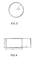
- Figure 3 shows the cross-section of a circular duct.
- Figure 4 shows the cross-section of a rectangular duct and a portion of the falling curtain.
- Figure 5 shows the lubricating liquid delivery duct of the present invention.
- Figure 6 shows the present invention and its relation to other standard pieces of the curtain coating process.
- the present invention relates to optimizing the geometry of the lubricating liquid delivery tube or channel to allow for the outlet to be placed very close to the hopper lip while avoiding turbulence at the outlet of the delivery tube.
- the prior art shown in Figure 1 uses a sharp 90° bend to turn the flow of the lubricating liquid vertically downward, i.e. parallel to the edge guide.
- Figure 1 shows an edge guide 12 in which lubricating liquid 15 is introduced through conduits 10 and 11.
- the conduits are joined at a sharp corner 16.
- the sharp corner 16 introduces a disturbance into the flow. In order for this disturbance to decay sufficiently, conduit 11 must be sufficiently long to allow flow at the outlet 14 to be laminar.
- FIG. 2 shows the lubricating liquid delivery tube of the present invention.
- the present invention introduces the lubricating liquid 15 through the delivery duct 21 to the outlet 24.
- the invention does not use the sharp 90° bend to turn the flow thus avoiding the turbulence the sharp bend creates. This allows the outlet to be closer to the hopper lip than in the prior art.
- the outlet is shown issuing lubricating liquid vertically downward to minimize disturbances as the curtain and lubrication layer merge but the outlet may issue fluid at any desired angle.
- the inlet length for the invention can be estimated by calculating the arc length of the curved path back to the inlet of the duct.
- the curve must be smooth but not necessarily circular. It is only necessary that the minimum radius of the curve, R, be sufficiently large.
- the present invention allows for the outlet of the lubricating water delivery tube to be much closer to the hopper lip while avoiding turbulence and associated manufacturing quality losses. Having the inlet closer to the hopper lip increases the momentum of the curtain near the edge allowing for higher coating speeds.
- the cross-section of duct which is used to deliver the lubricating liquid is chosen so as to provide a smooth transition for the curtain having its edge against the wall to having its edge against the lubricating liquid.
- the inlet length is given by the following relationship: [R.H. Perry, D. Green, Perry's Chemical Engineer's Handbook, 6th Ed, 1984, pp 5-35].
- D is the depth of the channel in cm used to deliver the lubricating liquid
- W is the width of the channel in cm used to deliver the lubricating liquid
- Q is the total flow rate in cm 3 /s of the liquid
- ⁇ is the viscosity in g/(cm-s) of the liquid
- ⁇ is the density in g/cm 3 of the liquid.
- FIG. 5 shows a final design with the parameters needed to determine the distance from the hopper lip.
- the delivery duct 21 has a radius R.
- the channel width W, or tube diameter D is also shown.
- the total length before the lubricating liquid is introduced, L L is the sum of the radius, R; channel width, W; and wall thickness, H. This is shown as R plus W plus H.
- Figure 6 shows a view of the lubricating liquid delivery tube 21 in its relative position with the hopper lip 61, edge guide 12, and substrate 60.
- the substrate is moved by conveying means such as a coating roll (not shown) through a free falling curtain.
- This is an overall view of how the invention fits with the curtain coating process.
- the lubricating liquid is delivered just after the hopper lip and flows down along the edge guide guiding the curtain to the substrate 60.
- the lubricating liquid is removed by liquid removing means 65, such as a slotted vacuum tube as shown in U.S. Patent 4,830,887.
Landscapes
- Chemical & Material Sciences (AREA)
- Engineering & Computer Science (AREA)
- Materials Engineering (AREA)
- Physics & Mathematics (AREA)
- General Physics & Mathematics (AREA)
- Coating Apparatus (AREA)
- Application Of Or Painting With Fluid Materials (AREA)
Claims (8)
- Vorrichtung zum Vorhangbeschichten eines Trägers durch Aufbringen einer oder mehrerer Beschichtungsflüssigkeiten auf den sich bewegenden Träger, wobei die Vorrichtung folgende Komponenten aufweist:dadurch gekennzeichnet, daßeine Fördereinrichtung mit einer Beschichtungswalze zum Bewegen des Trägers entlang einer Bahn durch eine Beschichtungszone;einen Beschichtungstrichter zum Erzeugen einer oder mehrerer Fließschichten von Beschichtungsflüssigkeiten, um einen zusammengesetzten, freifallenden Vorhang zu bilden, der sich quer über die Bahn erstreckt und auf dem sich bewegenden Träger auftrifft;voneinander beabstandete Kantenführungsmittel zum seitlichen Führen des fallenden Vorhangs;eine Flüssigkeitsverteilungseinrichtung mit einer Auslaßöffnung zum Abgeben einer Gleitflüssigkeit auf die Kantenführungsmittel, damit diese mit dem fallenden Vorhang in Benetzungskontakt bleiben;die Flüssigkeitsverteilungseinrichtung aus einer sanft gebogenen Röhre besteht, die nach dem Punkt der Verteilungseinrichtung, welcher der weiter stromabwärts liegende ist und bei dem die Turbulenz entsteht, eine Mindestlänge aufweist, die bewirkt, daß an der Auslaßöffnung eine Laminarströmung erzeugt wird.
- Vorrichtung nach Anspruch 1, dadurch gekennzeichnet, daß die Flüssigkeitsverteilungseinrichtung aus einer Leitung besteht, die einen kreisförmigen Querschnitt und eine Mindestlänge L nach dem Punkt der Verteilungseinrichtung aufweist, welcher der weiter stromabwärts liegende ist und bei dem die Turbulenz entsteht, ausgedrückt in cm und durch folgende Beziehung bestimmt:Q die Durchflußleistung durch die Leitung in cm3/s,ρ die Dichte der Gleitflüssigkeit in g/cm3, undµ die Viskosität der Gleitflüssigkeit in g/(cm.s) ist.
- Vorrichtung nach Anspruch 1, dadurch gekennzeichnet, daß die Flüssigkeitsverteilungseinrichtung aus einer Leitung besteht, die einen rechteckigen Querschnitt und eine Mindestlänge L nach dem Punkt der Verteilungseinrichtung aufweist, welcher der weiter stromabwärts liegende ist und bei dem die Turbulenz entsteht, ausgedrückt in cm und durch folgende Beziehuna bestimmt:wobei
 Q die Durchflußleistung durch die Leitung in cm3/s,D die quer zum Vorhang gemessene Tiefe der Leitung in cm,W die parallel zum Vorhang gemessene Breite der Leitung in cm,ρ die Dichte der Gleitflüssigkeit in g/cm3, undµ die Viskosität der Gleitflüssigkeit in g/(cm.s) ist.
 - Vorrichtung nach Anspruch 1, dadurch gekennzeichnet, daß die Gleitflüssigkeit Wasser bei etwa 40° C ist, und daß die Flüssigkeitsverteilungseinrichtung aus einer Leitung besteht, die einen kreisförmigen Querschnitt und eine Mindestlänge L nach dem Punkt der Verteilungseinrichtung aufweist, welcher der weiter stromabwärts liegende ist und bei dem die Turbulenz entsteht, ausgedrückt in cm und durch folgende Beziehung bestimmt:
- Vorrichtung nach Anspruch 1, dadurch gekennzeichnet, daß daß die Gleitflüssigkeit Wasser bei etwa 40° C ist, und daß die Flüssigkeitsverteilungseinrichtung aus einer Leitung besteht, die einen rechteckigen Querschnitt und eine Mindestlänge L nach dem Punkt der Verteilungseinrichtung aufweist, welcher der weiter stromabwärts liegende ist und bei dem die Turbulenz entsteht, ausgedrückt in cm und durch folgende Beziehung bestimmt:Q die Durchflußleistung durch die Leitung in cm3/s,D die quer zum Vorhang gemessene Tiefe der Leitung in cm, undW die parallel zum Vorhang gemessene Breite der Leitung in cm ist.
- Vorrichtung nach einem der Ansprüche 1 - 5, dadurch gekennzeichnet, daß die Leitung in ihrer Länge ein sanfte Krümmung mit einem minimalen Krümmungsradius zwischen etwa 0,6 und 1,2 cm aufweist.
- Vorrichtung nach einem der Ansprüche 1 - 6, gekennzeichnet durch eine Flüssigkeitsbeseitigungseinrichtung zum Abführen von Flüssigkeit aus dem Kantenbereich des freifallenden Vorhangs.
- Verfahren zum Vorhangbeschichten eines Trägers durch Aufbringen einer oder mehrerer Beschichtungsflüssigkeiten auf den sich bewegenden Träger, wobei das Verfahren folgende Schritte aufweist:dadurch gekennzeichnet, daß die Gleitflüssigkeit als Laminarströmung abgegeben wird.Bewegen des Trägers entlang einer Bahn durch eine Beschichtungszone;Erzeugen einer oder mehrerer Fließschichten von Beschichtungsflüssigkeiten, um einen zusammengesetzten freifallenden Vorhang zu bilden, der sich quer über die Bahn erstreckt und auf dem sich bewegenden Träger auftrifft;Verteilen einer Gleitflüssigkeit auf voneinander beabstandeten Kantenführungsmitteln zum seitlichen Führen des freifallenden Vorhangs, damit diese mit dem fallenden Vorhang in Benetzungskontakt bleiben;
Applications Claiming Priority (2)
| Application Number | Priority Date | Filing Date | Title |
|---|---|---|---|
| US07/993,479 US5358569A (en) | 1992-12-18 | 1992-12-18 | Curtain coating method and apparatus |
| US993479 | 1992-12-18 |
Publications (3)
| Publication Number | Publication Date |
|---|---|
| EP0603087A2 EP0603087A2 (de) | 1994-06-22 |
| EP0603087A3 EP0603087A3 (de) | 1994-11-17 |
| EP0603087B1 true EP0603087B1 (de) | 1999-04-21 |
Family
ID=25539601
Family Applications (1)
| Application Number | Title | Priority Date | Filing Date |
|---|---|---|---|
| EP93420491A Expired - Lifetime EP0603087B1 (de) | 1992-12-18 | 1993-12-10 | Vorhangsbeschichtungs- Verfahren und Vorrichtung |
Country Status (4)
| Country | Link |
|---|---|
| US (1) | US5358569A (de) |
| EP (1) | EP0603087B1 (de) |
| JP (1) | JPH06218314A (de) |
| DE (1) | DE69324553T2 (de) |
Families Citing this family (10)
| Publication number | Priority date | Publication date | Assignee | Title |
|---|---|---|---|---|
| US5382292A (en) * | 1993-07-28 | 1995-01-17 | Eastman Kodak Company | Edge guide lubricating fluid delivery apparatus |
| US6117236A (en) * | 1998-03-18 | 2000-09-12 | Eastman Kodak Company | Curtain coating apparatus and method with continuous width adjustment |
| US5976251A (en) * | 1998-12-17 | 1999-11-02 | Eastman Kodak Company | Inlet for introducing water to wire edge guides for curtain coating |
| DE19903260A1 (de) * | 1999-01-28 | 2000-08-03 | Agfa Gevaert Ag | Verfahren und Vorrichtung zum Vorhangbeschichten |
| US7172177B2 (en) * | 2004-04-15 | 2007-02-06 | Aeration Industries International, Inc. | Aerator |
| US8789492B2 (en) * | 2008-07-15 | 2014-07-29 | Awi Licensing Company | Coating apparatus and method |
| JP5593022B2 (ja) * | 2008-10-20 | 2014-09-17 | フロイント産業株式会社 | シームレスカプセル製造装置 |
| EP2412446A1 (de) * | 2010-07-30 | 2012-02-01 | Polytype Converting S.A. | Seitenberandung für Vorhangbeschichtungsverfahren |
| US9333524B2 (en) * | 2013-03-15 | 2016-05-10 | Ricoh Company, Ltd. | Slot curtain coating apparatus and slot curtain coating method |
| WO2022053548A1 (de) | 2020-09-14 | 2022-03-17 | Saint-Gobain Glass France | Verfahren und vorrichtung zum beschichten einer gebogenen scheibe mit einem photosensitiven material |
Family Cites Families (8)
| Publication number | Priority date | Publication date | Assignee | Title |
|---|---|---|---|---|
| US4075976A (en) * | 1974-03-04 | 1978-02-28 | A. Wiley Clayton | Apparatus for curtain coating objects |
| US4135477A (en) * | 1975-09-22 | 1979-01-23 | Ciba-Geigy Ag | Curtain coating apparatus |
| US4267795A (en) * | 1980-05-09 | 1981-05-19 | Crown Zellerbach Corporation | Liquid distributing apparatus |
| IT1218306B (it) * | 1982-10-06 | 1990-04-12 | Minnesota Mining & Mfg | Dispositivo di stesa e metodo per la stesa a cortina di composizioni liquide che impiega detto dispositivo |
| DE3300150A1 (de) * | 1983-01-04 | 1984-07-05 | Agfa-Gevaert Ag, 5090 Leverkusen | Verfahren und vorrichtung zur stabilisierung von frei fallenden fluessigkeitsvorhaengen |
| JPH01199668A (ja) * | 1988-02-01 | 1989-08-11 | Fuji Photo Film Co Ltd | 塗布装置 |
| US4830887A (en) * | 1988-04-22 | 1989-05-16 | Eastman Kodak Company | Curtain coating method and apparatus |
| JP3552113B2 (ja) * | 1992-04-21 | 2004-08-11 | 富士写真フイルム株式会社 | 塗布方法 |
-
1992
- 1992-12-18 US US07/993,479 patent/US5358569A/en not_active Expired - Fee Related
-
1993
- 1993-12-10 EP EP93420491A patent/EP0603087B1/de not_active Expired - Lifetime
- 1993-12-10 DE DE69324553T patent/DE69324553T2/de not_active Expired - Fee Related
- 1993-12-20 JP JP5319962A patent/JPH06218314A/ja not_active Ceased
Also Published As
| Publication number | Publication date |
|---|---|
| JPH06218314A (ja) | 1994-08-09 |
| EP0603087A2 (de) | 1994-06-22 |
| US5358569A (en) | 1994-10-25 |
| DE69324553T2 (de) | 1999-10-21 |
| EP0603087A3 (de) | 1994-11-17 |
| DE69324553D1 (de) | 1999-05-27 |
Similar Documents
| Publication | Publication Date | Title |
|---|---|---|
| EP0636423B1 (de) | Vorrichtung zur Abgabe einer Gleitflüssigkeit einer Randkantenführung | |
| US5395660A (en) | Edge removal apparatus for curtain coating | |
| EP0603087B1 (de) | Vorhangsbeschichtungs- Verfahren und Vorrichtung | |
| AU616009B2 (en) | Curtain coating method and apparatus | |
| EP0400055B1 (de) | Verfahren zum vorhangbeschichtungsstart und vorrichtung | |
| US4384015A (en) | Process and an apparatus for simultaneously coating several layers to moving objects, particularly webs | |
| EP0808220B1 (de) | Verfahren zur herstellung von mehrschichtiger bechichtungen | |
| JP3592736B2 (ja) | 流し塗り用エッジガイド装置及び方法 | |
| US7169445B2 (en) | Method and apparatus for curtain coating | |
| EP0537086B1 (de) | Vorhangbeschichtungsmethode und Vorrichtung | |
| EP2292336A1 (de) | Vorhangbeschichter und Verfahren zur Vorhangbeschichtung | |
| Benkreira et al. | Classification and analyses of coating flows | |
| EP0154656B1 (de) | Beschichtungsvorrichtung | |
| JP6241333B2 (ja) | スロットカーテン塗布装置及びスロットカーテン塗布方法 | |
| WO1990001179A1 (en) | Curtain coating method and apparatus | |
| JPH0747319A (ja) | カーテンコーティング装置および方法 | |
| EP0649054B1 (de) | Vorrichtung und Verfahren für interne Kantenführungsstreifen | |
| JP5605098B2 (ja) | カーテン塗布装置及びカーテン塗布方法 | |
| JPH0759309B2 (ja) | 塗布装置 | |
| JPH0215267B2 (de) | ||
| JPH11165108A (ja) | カーテンコーティング装置のワイヤエッジガイド用の組み合わされた水投入部とベンドバック・フラグ |
Legal Events
| Date | Code | Title | Description |
|---|---|---|---|
| PUAI | Public reference made under article 153(3) epc to a published international application that has entered the european phase |
Free format text: ORIGINAL CODE: 0009012 |
|
| AK | Designated contracting states |
Kind code of ref document: A2 Designated state(s): BE DE NL |
|
| PUAL | Search report despatched |
Free format text: ORIGINAL CODE: 0009013 |
|
| AK | Designated contracting states |
Kind code of ref document: A3 Designated state(s): BE DE FR GB NL |
|
| 17P | Request for examination filed |
Effective date: 19950512 |
|
| 17Q | First examination report despatched |
Effective date: 19951011 |
|
| GRAG | Despatch of communication of intention to grant |
Free format text: ORIGINAL CODE: EPIDOS AGRA |
|
| GRAG | Despatch of communication of intention to grant |
Free format text: ORIGINAL CODE: EPIDOS AGRA |
|
| GRAH | Despatch of communication of intention to grant a patent |
Free format text: ORIGINAL CODE: EPIDOS IGRA |
|
| RBV | Designated contracting states (corrected) |
Designated state(s): BE DE NL |
|
| GRAH | Despatch of communication of intention to grant a patent |
Free format text: ORIGINAL CODE: EPIDOS IGRA |
|
| GRAA | (expected) grant |
Free format text: ORIGINAL CODE: 0009210 |
|
| AK | Designated contracting states |
Kind code of ref document: B1 Designated state(s): BE DE NL |
|
| REF | Corresponds to: |
Ref document number: 69324553 Country of ref document: DE Date of ref document: 19990527 |
|
| PLBE | No opposition filed within time limit |
Free format text: ORIGINAL CODE: 0009261 |
|
| STAA | Information on the status of an ep patent application or granted ep patent |
Free format text: STATUS: NO OPPOSITION FILED WITHIN TIME LIMIT |
|
| 26N | No opposition filed | ||
| PGFP | Annual fee paid to national office [announced via postgrant information from national office to epo] |
Ref country code: NL Payment date: 20051109 Year of fee payment: 13 |
|
| PGFP | Annual fee paid to national office [announced via postgrant information from national office to epo] |
Ref country code: DE Payment date: 20051230 Year of fee payment: 13 |
|
| PGFP | Annual fee paid to national office [announced via postgrant information from national office to epo] |
Ref country code: BE Payment date: 20060113 Year of fee payment: 13 |
|
| PG25 | Lapsed in a contracting state [announced via postgrant information from national office to epo] |
Ref country code: BE Free format text: LAPSE BECAUSE OF NON-PAYMENT OF DUE FEES Effective date: 20061231 |
|
| PG25 | Lapsed in a contracting state [announced via postgrant information from national office to epo] |
Ref country code: NL Free format text: LAPSE BECAUSE OF NON-PAYMENT OF DUE FEES Effective date: 20070701 |
|
| PG25 | Lapsed in a contracting state [announced via postgrant information from national office to epo] |
Ref country code: DE Free format text: LAPSE BECAUSE OF NON-PAYMENT OF DUE FEES Effective date: 20070703 |
|
| NLV4 | Nl: lapsed or anulled due to non-payment of the annual fee |
Effective date: 20070701 |
|
| BERE | Be: lapsed |
Owner name: *EASTMAN KODAK CY Effective date: 20061231 |