EP0603103A2 - Verbindungsverfahren für digitale Multimediakommunikationen - Google Patents
Verbindungsverfahren für digitale Multimediakommunikationen Download PDFInfo
- Publication number
- EP0603103A2 EP0603103A2 EP93480192A EP93480192A EP0603103A2 EP 0603103 A2 EP0603103 A2 EP 0603103A2 EP 93480192 A EP93480192 A EP 93480192A EP 93480192 A EP93480192 A EP 93480192A EP 0603103 A2 EP0603103 A2 EP 0603103A2
- Authority
- EP
- European Patent Office
- Prior art keywords
- network
- node
- lan
- receiving
- nodes
- Prior art date
- Legal status (The legal status is an assumption and is not a legal conclusion. Google has not performed a legal analysis and makes no representation as to the accuracy of the status listed.)
- Withdrawn
Links
Images


Classifications
-
- H—ELECTRICITY
- H04—ELECTRIC COMMUNICATION TECHNIQUE
- H04L—TRANSMISSION OF DIGITAL INFORMATION, e.g. TELEGRAPHIC COMMUNICATION
- H04L12/00—Data switching networks
- H04L12/28—Data switching networks characterised by path configuration, e.g. LAN [Local Area Networks] or WAN [Wide Area Networks]
-
- H—ELECTRICITY
- H04—ELECTRIC COMMUNICATION TECHNIQUE
- H04L—TRANSMISSION OF DIGITAL INFORMATION, e.g. TELEGRAPHIC COMMUNICATION
- H04L25/00—Baseband systems
- H04L25/02—Details ; arrangements for supplying electrical power along data transmission lines
- H04L25/14—Channel dividing arrangements, i.e. in which a single bit stream is divided between several baseband channels and reassembled at the receiver
Definitions
- the present invention relates to dynamic configuration of local area networks (LANs) and, more particularly, to a method of LAN configuration to enable full-bandwidth communications among selected computing equipment.
- the invention concerns an apparatus and method for allocating private connections via a LAN switching mechanism.
- image (video) transmission requires a vast amount of data to be transmitted across a network and drives the need for high-speed data transfer.
- Image transmission is required in tools such as computer-aided engineering software, for such applications as solid modeling, computer-aided electronic design, and visualization.
- Even greater network performance is necessary where video and audio information are transmitted across networks in applications such as teleconferencing, education, marketing, news, and entertainment.
- Data compression is one method of freeing up some of the bandwidth absorbed by the video/audio data transfer (real-time compression is available today at 160:1) but inherently results in a loss of at least some data. In many applications, lossy compression is tolerable. Other applications can tolerate only lossless compression, thereby requiring exclusive use of a substantial portion of the available transmission bandwidth.
- Ethernet (10Mbps) and Token Ring (4/16Mbps) LANs can transmit compressed image
- neither network can sustain more than a handful of live-running video sessions.
- some applications that require high-quality image may necessitate the dedication of the complete LAN bandwidth to a single user.
- those with multiple units attached on a bus or a ring it is conceivable that several multimedia users could consume the entire bandwidth, thereby creating performance problems with other traffic on the network.
- FDDI Fiber Distributed Data Interface
- FDDI-2 offers time multiplexing to reduce the protocol overhead.
- FDDI and FDDI-2 are, however, expensive to install, especially where the network components are already established.
- an intelligent hub Another approach to guaranteeing full bandwidth to end users is the use of what is called an "intelligent hub".
- This network device connects each user with a dedicated LAN interface, for example, an Ethernet bus, which results in each user being assured free use of the available LAN bandwidth, 10Mbps in this example.
- Data is transferred from one user to another via bridging.
- the bridging process introduces delays (latency) that are detrimental to some multimedia applications.
- an intelligent hub may be somewhat effective in that existing cable media and terminal communications adapters can be used, the cost for these devices can be prohibitive.
- Reconfiguration of a network which can be accomplished by rearranging the interconnections on a LAN, for example, is a method of providing necessary LAN bandwidth for its corresponding LAN stations. For example, if performance is poor, the network may be divided into two or more "subLANs" and then interconnected with a bridge. In this way, each subLAN has the maximum LAN bandwidth and, therefore, each station has less competition for the available bandwidth.
- this reconfiguration is accomplished by rearranging the connections at the multistation access units (MAUs) which are utilized to provide the appropriate connectivity.
- MAUs multistation access units
- the challenge is to develop a method to manage the bandwidth of a low-cost network that will permit multimedia (audio/video) communications along with other, less demanding traffic.
- the primary object of this invention is to provide an apparatus and method for allocating bandwidth on LANs, such as Ethernet (CSMA/CD, IEEE 802.3) or Token Ring (IEEE 802.5), that effectively, yet economically, enables multimedia communications.
- LANs such as Ethernet (CSMA/CD, IEEE 802.3) or Token Ring (IEEE 802.5)
- Another object is to provide an apparatus and method for dynamically reconstructing network configurations and for assuring optimal network performance.
- Another object is to provide a method of establishing point-to-point connections by reconfiguration of the local area network to enable isochronous communication between two computing devices.
- Yet another object is to provide a method of managing the dynamic reconfiguration of the network.
- the above and other objects are achieved by the invention, which comprises in a preferred embodiment a network controller apparatus for dynamically rearranging a LAN to guarantee bandwidth required for multimedia communications.
- the network controller comprises a switch connected to the transmit and receive ports of each LAN station and to a switch controller.
- the switch comprises an internal switching fabric such that any receive port can be directly connected to any transmit port of any of the stations.
- the switch controller has a microprocessor for providing network control, a memory for providing storage, a LAN interface for providing access to the LAN, a switch control unit for providing control signals to the switch, and DC detection circuitry for detecting signals from each of the stations.
- the network controller of the present invention initially configures the network in a single, common ring comprising the stations and the network controller, wherein normal LAN activity occurs.
- a station requires additional bandwidth for data transmission with another station such that it cannot share the common ring bandwidth with the remaining stations, it sends a request to the controller requesting a different LAN configuration.
- a station may request to be temporarily removed from the primary ring for exclusive communication with another station thereby having use of the full LAN bandwidth of the new "subLAN". This request is normally sent in a packet being passed around the common ring.
- one of the stations issues a request to the network controller to reconfigure the network. Because the stations are out of the common ring, the station makes the request by applying a DC voltage to one of its receive or transmit line pairs. The network controller detects this signal with its DC detection circuitry and reconfigures the network accordingly.
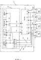
- FIG. 1 is a block diagram showing the network controller of the present invention with a plurality of workstations connected thereto.
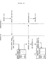
- FIG. 2 is a flow chart showing at a high level the network configuration processes.
- FIG. 3 is a flow chart showing the network log-in process.
- FIG. 4 is a flow chart showing the network log-off process.
- FIG. 5 is a flow chart showing the private session establishment process.
- FIG. 6 is a flow chart showing the private session break process.
- FIG. 1 shows a diagram of a network consisting of a network controller 10 of the present invention and workstations 12a, 12b, 12c and 12d (WS1 through WS4) connected thereto.
- Each workstation has two ports, a transmit port (T) and a receive port (R), for being connected to the network controller via LAN lines 14a, 16a, 14b, 16b, 14c, 16c, 14d and 16d.
- the ports of the workstations are attached to ports of the controller 10 (in contrast to being attached to a multistation access unit (MAU) as they are today).
- MAU multistation access unit
- Controller 10 comprises a switching device 18 having a plurality of input ports, in this case, five, (I1 through I4, Ic) and a plurality of output ports (O1 through O4, Oc) .
- Each of input ports I1 through I4 is connected, respectively, to a transmit port (T) of one of the workstations WS1 through WS4.
- each of the four output ports O1 through O4 is connected to a receive port (R) of one of the workstations WS1 through WS4.
- the remaining two ports Ic and Oc are used to allow the network controller access to the network.
- Switching device 18 has an internal switching fabric so that any of the input ports (I1 through I4, Ic) may be connected to any of the output ports (O1 through 04, Oc).
- An example of such a switching device is the well-known non-blocking cross-bar switch. Control of the switching device 18 is provided by control lines 20 connected to the CTL IN port.
- Network controller 10 further consists of a switch controller 22 which controls the configuration of the switch 18.
- the switch controller 22 is connected to the network via lines 14e and 16e.
- switch controller 22 is connected to LAN lines 14a, 14b, 14c and 14d via DC detection lines 24a, 24b, 24c and 24d.
- Switch controller 22 consists of a memory 26 for providing local storage, a processor 28 for providing processing capability, a LAN interface (LAN I/F) 30 for providing an interface to the LAN, a switch control unit 32 for providing the control signals to switch 18 and a DC detection unit 34 for detecting any DC variations on LAN lines 14a, 14b, 14c and 14d.
- Processor 28, LAN I/F 30, switch control unit 32 and DC detection unit 34 are interconnected by an internal common bus 36.
- Processor 28 and memory 26 are interconnected by a separate bus 38.
- processor 28 provides the intelligence for the network controller 10. It has the capability of communicating via the LAN I/F 30 with all nodes active on the common ring. It also provides management and control of switch 18 via switch control unit 32. Through DC detection unit 34, the processor 28 can detect DC voltage variations issued from the workstations for communication purposes. This will be discussed in greater detail below.
- Memory 26 is utilized by providing local storage for the processor of control programs, switch configuration tables, etc.
- LAN I/F 30 has a receive (R) port and a transmit (T) port and is connected to switch 18 via lines 14e and 16e.
- LAN I/F 30 acts as the LAN interface between the common, primary LAN and the processor 28.
- LAN I/F 30 is always placed by the switch into the LAN network as a common ring node.
- Switch control unit 32 receives commands from the processor 28 and translates these commands into switch control signals which sent to the switch 18 via control lines 20.
- the DC detection unit 34 is used to detect DC voltage variations from the workstations WS1 through WS4.
- a DC voltage variation from a workstation to the MAU energized a relay in the MAU which physically connected workstation into the ring, i.e., the transmit and receive ports of the workstation were physically connected to the appropriate transmit and receive ports of the directly adjacent workstations, or nodes.
- a +5vDC signal (“OPEN" command) was generated by the workstation token ring adapter and sent to the MAU. This signal provides the energy to activate the relay in the MAU that places the node actively into the network.
- the DC voltage variation from a workstation is detected by the DC detection unit 34 and is conveyed to the processor 28 via common bus 36.
- the DC variation in this case, represents a soft request to the network controller 10 for changing the network configuration so that the workstation is entered into the common ring.
- the DC variation is used by the workstation in two instances. First, the workstation uses it initially to enter the common ring. Second, after the workstation has been taken of the common ring, it generates the DC offset to re-enter the common ring as it has no other method of communicating with the network controller 10.
- the +5vDC signal from the workstation adapter is detected by the DC detection unit 34, conveyed to the processor 28, and interpreted as a request from the workstation to be placed back into the primary, common ring.
- the network controller 10 detects, via DC detection unit 34, +5vDC offset signals on the workstation transmit LAN lines of those workstations wishing to enter the common ring.
- the network controller 10 then configures the network in a single, primary ring having each of the workstations WS1 through WS4 and the network controller 10 as stations on the primary ring. This is accomplished by configuring switch 18 such that the input port for a first workstation (I1 for WS1, for example) is connected to the output port of the next workstation (O2 for WS2).
- switch 22 could be initially configured for the sample network is detailed in Table 1 below, wherein Port 1 is connected to Port 2 within switch 18: TABLE 1 Port 1 Port 2 I1 O2 I2 O3 I3 O4 I4 Oc Ic O1 (As noted above, switch 18 is controlled via control lines 20 from switch control unit 32.) In this switch configuration, each workstation WS1 through WS4 and switch controller 22 is on the primary Token Ring network.
- the processor 28 maintains, in memory 26, a map of the port input and output connections and the switch internal connections. These tables, and other tables maintained by the processor 28, will be discussed in greater detail below.
- the network can be reconfigured by the network controller 10.
- An example of this type of situation is where one workstation is a client and the second workstation is a server, with audio and image data streams need to be continuously transmitted, for a period of time, between the server and the client.
- the workstation requiring network reconfiguration issues a request to the network controller 10 in a message using the associated networking protocol.
- the message (or messages) to the network controller 10 specifies with which workstation (or workstations) an isolated ring needs to be established. For example, when WS1 needs to exclusively communicate with WS2, WS1 sends a message to the network controller 10 requesting the corresponding network reconfiguration.
- the network controller 10 Upon receipt of the request, the network controller 10 first checks to see if the requested resource is available from a resource availability table and, if so, interrupts the network and reconfigures the switch so that the receive port of the requesting node is connected to the transmit port of the resource and the transmit port of the requesting node is connected to the transmit port of the resource.
- the two nodes are connected in a private connection and no longer-belong to the common ring.
- the network controller resets the rest of the common ring, excluding the point-to-point connection, and updates the resource availability table.
- the requesting node Upon completion of the data transfer between the two now-isolated nodes, i.e, WS1 and WS2 in this example, the requesting node (WS1) modulates its transmit LAN line (14a) with a +5vDC signal.
- the DC detection unit 34 detects the +5vDC variation and conveys this to the processor 28.
- the processor 28 then reconfigures the network so that the two nodes (WS1 and WS2) are re-entered in the common ring.
- Fig. 2 illustrates a high level flow diagram of network activity.
- the network controller goes through a system boot process for initiating the network.
- it initiates the network. This includes such functions as performing diagnostics, setting the initial switch configuration, etc.
- workstation 1 client logs into the network. As discussed above, this is accomplished by the workstation modulating its transmit LAN line with a +5vDC signal which is detected by the DC detection unit of the network controller.
- the network controller logs workstation 1 in for interconnection in the common ring, the details of which are discussed below.
- workstation 2 (server) logs into the common ring in the same manner.
- the network controller configures the network by issuing the proper switch commands to the cross-bar switch.
- workstation 1 client
- workstation 2 server
- the network controller establishes the session by properly configuring the switch.
- the two workstations privately communicate off-line from the common LAN so that the maximum bandwidth can be utilized.
- workstations 1 and 2 request that the session be terminated. Again, this is accomplished by the workstations modulating their respective transmit LAN lines with a +5vDC signal which the network controller detects and acts upon.
- the network controller terminates the session and reconfigures the LAN so that workstations 1 and 2 are re-entered therein.
- workstations 1 and 2 log off the network and, at 78, the network controller brings down the common LAN.
- Figure 3 illustrates a flow chart having greater detail of the network configuration processes. In particular, it illustrates the interactive log-in process between a node and the network controller.
- the processes and message flows of Figure 3 are of a single workstation rather than for multiple workstations.
- the workstation boots and runs a self-diagnostic test.
- the workstation activates itself with respect to the common ring by modulating its LAN line with a +5vDC signal.
- the network controller detects the modulation.
- the network controller rebuilds its LAN configuration table (CONFIG_TABLE) and reconfigures the common LAN (by setting the switch) so that the workstation is included in the ring.
- the configuration table (CONFIG_TABLE) is a table stored in memory in which the processor keeps track of the present switch configuration.
- the workstation identifies to the network controller its physical node address and the resource, if any, it can provide to the network.
- a laser disk player is an example of a resource.
- the network controller updates its available resource table (FREELIST) with the workstation's information.
- the workstation is on-line common LAN.
- Figure 4 illustrates the interactive log-out process for removing a node from the common network.
- the node is on-line.
- the node notifies the network controller that it wishes to be logged out.
- the network controller rebuilds its LAN configuration table, deactivating the requesting node.
- the network controller confirms the log-out with the node.
- the node becomes inactive and goes off-line at 113.
- the network controller sets switch to the new configuration, removing the node from the common ring.
- the network controller updates its available resource list (FREELIST), removing the node therefrom.
- FREELIST available resource list
- FIG. 5 is a flow chart showing in detail the process involved in establishing a private session between two nodes when the nodes are on-line common LAN.
- both nodes are on-line common LAN.
- workstation 1 (Client) requests to the network controller that a private session be established between workstation 1 (Client) and workstation 2 (Server).
- the network controller checks the FREELIST and to determine whether Server is available. If so, at 124, the network controller reserves the resource (Server) by removing it from the FREELIST.
- the network controller issues a notification to both workstation 1 and workstation 2 that a private session is impending.
- both workstation 1 and workstation 2 deactivate by dropping their +5vDC signals, indicating that they are ready for the private session.
- the controller detects the signal drop at 130 and reconfigures the network by building a CONFIG_TABLE (a table specifying the new switch configuration) at 132 and by setting the switch at 134.
- CONFIG_TABLE a table specifying the new switch configuration
- workstation 1 and workstation 2 reactivate at 136 by raising the +5vDC signal and begin private communication at 137.
- the controller detects this as a successful establishment of the private session. If either workstation 1 or workstation 2 does not reactivate, the controller will take them completely out of the network until each reactivates.
- FIG. 6 illustrates a flow chart showing the process by which a private session is broken by one of the parties in the private session.
- workstation (WS) 1 and WS2 have an established private session.
- WS1 requests that the session be ended.
- each node deactivates by dropping its +5vDC line.
- the controller detects the +5vDC drops at 148 and checks the configuration table at 150 to determine whether the nodes were having a private session.
- the controller waits for the nodes to reactivate by raising the +5vDC line. If, after a predetermined period of time, the nodes do not reactivate, the processor removes them completely from the private and common rings.
- both nodes reactivate.
- the controller builds a new configuration table having the nodes back in the common ring. The controller then sets the switch at 160 so that the nodes are back on-line on common LAN.
- the controller updates the FREELIST and, at 166, notifies the nodes that they are on-line common LAN.
- one controller has been described as controlling the configuration of a single LAN.
- Other scenarios can exist, however, where multiple controllers may be utilized to control the configuration and interconnection of multiple LANs and multiple subLANs with additional MAUs.
- the different utilizations are nearly endless.
Landscapes
- Engineering & Computer Science (AREA)
- Computer Networks & Wireless Communication (AREA)
- Signal Processing (AREA)
- Power Engineering (AREA)
- Data Exchanges In Wide-Area Networks (AREA)
- Computer And Data Communications (AREA)
- Small-Scale Networks (AREA)
Applications Claiming Priority (2)
| Application Number | Priority Date | Filing Date | Title |
|---|---|---|---|
| US07/989,669 US5289461A (en) | 1992-12-14 | 1992-12-14 | Interconnection method for digital multimedia communications |
| US989669 | 1992-12-14 |
Publications (2)
| Publication Number | Publication Date |
|---|---|
| EP0603103A2 true EP0603103A2 (de) | 1994-06-22 |
| EP0603103A3 EP0603103A3 (de) | 1995-02-01 |
Family
ID=25535341
Family Applications (1)
| Application Number | Title | Priority Date | Filing Date |
|---|---|---|---|
| EP93480192A Withdrawn EP0603103A3 (de) | 1992-12-14 | 1993-11-19 | Verbindungsverfahren für digitale Multimediakommunikationen. |
Country Status (4)
| Country | Link |
|---|---|
| US (1) | US5289461A (de) |
| EP (1) | EP0603103A3 (de) |
| JP (1) | JP2539168B2 (de) |
| CA (1) | CA2105352A1 (de) |
Families Citing this family (47)
| Publication number | Priority date | Publication date | Assignee | Title |
|---|---|---|---|---|
| JPH0756754A (ja) * | 1993-08-03 | 1995-03-03 | Internatl Business Mach Corp <Ibm> | マルチメディア・グループ資源割当て装置及び方法 |
| US5673393A (en) * | 1993-11-24 | 1997-09-30 | Intel Corporation | Managing bandwidth over a computer network having a management computer that allocates bandwidth to client computers upon request |
| US5600797A (en) * | 1993-11-24 | 1997-02-04 | Intel Corporation | System for identifying new client and allocating bandwidth thereto by monitoring transmission of message received periodically from client computers informing of their current status |
| CA2118278C (en) * | 1993-12-21 | 1999-09-07 | J. David Garland | Multimedia system |
| US5515511A (en) * | 1994-06-06 | 1996-05-07 | International Business Machines Corporation | Hybrid digital/analog multimedia hub with dynamically allocated/released channels for video processing and distribution |
| US5640384A (en) * | 1994-06-13 | 1997-06-17 | U.S. Philips Corporation | Reconfigurable communication network |
| EP0700205A3 (de) * | 1994-08-31 | 1997-04-02 | Toshiba Kk | Multimediafernsehempfänger und Initialisierungsverfahren dafür |
| US5603058A (en) * | 1994-09-08 | 1997-02-11 | International Business Machines Corporation | Video optimized media streamer having communication nodes received digital data from storage node and transmitted said data to adapters for generating isochronous digital data streams |
| US5668948A (en) * | 1994-09-08 | 1997-09-16 | International Business Machines Corporation | Media streamer with control node enabling same isochronous streams to appear simultaneously at output ports or different streams to appear simultaneously at output ports |
| US5712976A (en) * | 1994-09-08 | 1998-01-27 | International Business Machines Corporation | Video data streamer for simultaneously conveying same one or different ones of data blocks stored in storage node to each of plurality of communication nodes |
| US5586264A (en) * | 1994-09-08 | 1996-12-17 | Ibm Corporation | Video optimized media streamer with cache management |
| US5761417A (en) * | 1994-09-08 | 1998-06-02 | International Business Machines Corporation | Video data streamer having scheduler for scheduling read request for individual data buffers associated with output ports of communication node to one storage node |
| CA2153445C (en) * | 1994-09-08 | 2002-05-21 | Ashok Raj Saxena | Video optimized media streamer user interface |
| US5613061A (en) * | 1994-09-12 | 1997-03-18 | Verilink Corporation | Network controller with reconfigurable program logic circuits capable of performing both channel service and testing functions |
| US5784570A (en) * | 1995-04-07 | 1998-07-21 | At&T Corp | Server for applying a recipient filter and compressing the input data stream based upon a set of at least one characteristics in a multiuser interactive virtual environment |
| US5719862A (en) * | 1996-05-14 | 1998-02-17 | Pericom Semiconductor Corp. | Packet-based dynamic de-skewing for network switch with local or central clock |
| US6031843A (en) * | 1996-11-21 | 2000-02-29 | Alcatel Data Networks Inc. | Digital communications switching fabric |
| US6088728A (en) * | 1997-06-11 | 2000-07-11 | Oracle Corporation | System using session data stored in session data storage for associating and disassociating user identifiers for switching client sessions in a server |
| US6243751B1 (en) * | 1997-06-11 | 2001-06-05 | Oracle Corporation | Method and apparatus for coupling clients to servers |
| US6064668A (en) * | 1997-10-31 | 2000-05-16 | Sp Controls, Inc. | Device control apparatus having input device selection switch with rubberized key |
| FR2772154A1 (fr) | 1997-12-09 | 1999-06-04 | Motorola Semiconducteurs | Circuit de commande pour la correction du facteur de puissance |
| WO1999053627A1 (en) | 1998-04-10 | 1999-10-21 | Chrimar Systems, Inc. Doing Business As Cms Technologies | System for communicating with electronic equipment on a network |
| US7013339B2 (en) * | 1998-07-06 | 2006-03-14 | Sony Corporation | Method to control a network device in a network comprising several devices |
| US6480510B1 (en) * | 1998-07-28 | 2002-11-12 | Serconet Ltd. | Local area network of serial intelligent cells |
| US6505255B1 (en) | 1999-04-29 | 2003-01-07 | Mitsubishi Electric Information Technology Center America, Inc. (Ita) | Method for formatting and routing data between an external network and an internal network |
| US6496862B1 (en) | 1998-08-25 | 2002-12-17 | Mitsubishi Electric Research Laboratories, Inc. | Remote monitoring and control of devices connected to an IEEE 1394 bus via a gateway device |
| US9239763B2 (en) | 2012-09-28 | 2016-01-19 | Oracle International Corporation | Container database |
| US6523064B1 (en) | 1999-04-29 | 2003-02-18 | Mitsubishi Electric Research Laboratories, Inc | Network gateway for collecting geographic data information |
| US6378000B1 (en) | 1999-04-29 | 2002-04-23 | Mitsubish Electric Research Laboratories, Inc | Address mapping in home entertainment network |
| US6633547B1 (en) | 1999-04-29 | 2003-10-14 | Mitsubishi Electric Research Laboratories, Inc. | Command and control transfer |
| US6956826B1 (en) | 1999-07-07 | 2005-10-18 | Serconet Ltd. | Local area network for distributing data communication, sensing and control signals |
| US6842459B1 (en) | 2000-04-19 | 2005-01-11 | Serconet Ltd. | Network combining wired and non-wired segments |
| US20020143910A1 (en) * | 2001-03-29 | 2002-10-03 | Shih-Wei Chou | Network hub |
| WO2002096029A1 (en) * | 2001-05-18 | 2002-11-28 | Telstra Corporation Limited | Network bandwidth control |
| US7177971B2 (en) * | 2001-08-24 | 2007-02-13 | Intel Corporation | General input/output architecture, protocol and related methods to provide isochronous channels |
| ATE335237T1 (de) | 2001-08-24 | 2006-08-15 | Intel Corp | Eine allgemeine eingabe-/ausgabearchitektur, protokoll und entsprechende verfahren zur umsetzung der flusssteuerung |
| US9836424B2 (en) | 2001-08-24 | 2017-12-05 | Intel Corporation | General input/output architecture, protocol and related methods to implement flow control |
| JP4080970B2 (ja) * | 2003-07-30 | 2008-04-23 | 株式会社日立製作所 | パス切替えを提供するスイッチ |
| US7502824B2 (en) * | 2004-08-12 | 2009-03-10 | Oracle International Corporation | Database shutdown with session migration |
| US7415470B2 (en) * | 2004-08-12 | 2008-08-19 | Oracle International Corporation | Capturing and re-creating the state of a queue when migrating a session |
| DE102004062116B3 (de) * | 2004-12-23 | 2006-05-11 | Ab Skf | Lageranordnung für einen Computertomographen |
| US9176772B2 (en) * | 2005-02-11 | 2015-11-03 | Oracle International Corporation | Suspending and resuming of sessions |
| CN101809971A (zh) * | 2007-09-28 | 2010-08-18 | 爱立信电话股份有限公司 | 用于电信网络中的协议协商的方法、系统和设备 |
| US8549038B2 (en) | 2009-06-15 | 2013-10-01 | Oracle International Corporation | Pluggable session context |
| US10289617B2 (en) | 2015-12-17 | 2019-05-14 | Oracle International Corporation | Accessing on-premise and off-premise datastores that are organized using different application schemas |
| US10387387B2 (en) | 2015-12-17 | 2019-08-20 | Oracle International Corporation | Enabling multi-tenant access to respective isolated data sets organized using different application schemas |
| US10303894B2 (en) | 2016-08-31 | 2019-05-28 | Oracle International Corporation | Fine-grained access control for data manipulation language (DML) operations on relational data |
Family Cites Families (16)
| Publication number | Priority date | Publication date | Assignee | Title |
|---|---|---|---|---|
| US4491838A (en) * | 1982-07-28 | 1985-01-01 | International Business Machines Corporation | Starloop communication network and control system therefor |
| US4679191A (en) * | 1983-05-04 | 1987-07-07 | Cxc Corporation | Variable bandwidth switching system |
| JPS6118242A (ja) * | 1984-06-29 | 1986-01-27 | インタ−ナショナル ビジネス マシ−ンズ コ−ポレ−ション | 通信ネツトワ−ク |
| US4710917A (en) * | 1985-04-08 | 1987-12-01 | Datapoint Corporation | Video conferencing network |
| NL8601712A (nl) * | 1986-07-01 | 1988-02-01 | Koninkl Philips Electronics Nv | Communicatienetwerk, in het bijzonder een telefoonnetwerk en datacommunicatienetwerk dat is samengesteld uit een verzameling van knooppuntseenheden, waarbij specifieke faciliteiten binnen naar keuze vastgestelde domeinen, volledig geintegreerd kunnen worden geboden. |
| US4797877A (en) * | 1986-12-18 | 1989-01-10 | American Telephone And Telegraph Company | Communication system dynamic conferencer circuit |
| EP0290934B1 (de) * | 1987-05-14 | 1994-01-19 | Siemens Aktiengesellschaft | Verfahren zum Bilden einer Adressentabelle in einem ringförmigen Kommunikationsnetz |
| US4975906A (en) * | 1988-02-15 | 1990-12-04 | Hitachi, Ltd. | Network system |
| US4931950A (en) * | 1988-07-25 | 1990-06-05 | Electric Power Research Institute | Multimedia interface and method for computer system |
| JP3002471B2 (ja) * | 1988-08-19 | 2000-01-24 | 株式会社日立製作所 | 番組配信装置 |
| US5091849A (en) * | 1988-10-24 | 1992-02-25 | The Walt Disney Company | Computer image production system utilizing first and second networks for separately transferring control information and digital image data |
| JPH02211738A (ja) * | 1989-02-13 | 1990-08-23 | Hitachi Ltd | 回線制御装置 |
| US5014267A (en) * | 1989-04-06 | 1991-05-07 | Datapoint Corporation | Video conferencing network |
| JPH0369219A (ja) * | 1989-08-08 | 1991-03-25 | Toyota Autom Loom Works Ltd | 移動体通信装置 |
| JPH03108845A (ja) * | 1989-09-21 | 1991-05-09 | Toshiba Corp | 輻輳回避制御方式 |
| US5121382A (en) * | 1989-10-11 | 1992-06-09 | Digital Equipment Corporation | Station-to-station full duplex communication in a communications network |
-
1992
- 1992-12-14 US US07/989,669 patent/US5289461A/en not_active Expired - Lifetime
-
1993
- 1993-09-01 CA CA002105352A patent/CA2105352A1/en not_active Abandoned
- 1993-11-17 JP JP5287929A patent/JP2539168B2/ja not_active Expired - Fee Related
- 1993-11-19 EP EP93480192A patent/EP0603103A3/de not_active Withdrawn
Also Published As
| Publication number | Publication date |
|---|---|
| EP0603103A3 (de) | 1995-02-01 |
| US5289461A (en) | 1994-02-22 |
| JP2539168B2 (ja) | 1996-10-02 |
| CA2105352A1 (en) | 1994-06-15 |
| JPH06232891A (ja) | 1994-08-19 |
Similar Documents
| Publication | Publication Date | Title |
|---|---|---|
| US5289461A (en) | Interconnection method for digital multimedia communications | |
| US6092214A (en) | Redundant network management system for a stackable fast ethernet repeater | |
| US5577033A (en) | Local area network transmission emulator | |
| US6687751B1 (en) | Multi-point link aggregation spoofing | |
| US5946311A (en) | Method for allowing more efficient communication in an environment wherein multiple protocols are utilized | |
| JP2501954B2 (ja) | ト―クン・リング・ロ―カル・エリア・ネットワ―クにおける端局間全二重通信 | |
| US8306055B2 (en) | Method and system to support wireless multicast transmission | |
| EP0755012A2 (de) | Serielle Hochgeschwindigkeitsdatenübertragungsverbindung für Tischperipheriegeräte | |
| US7463647B2 (en) | Method of and apparatus for providing reserved bandwidth to ethernet devices over switched ethernet including a home network wall plate having a combined IEEE 1394 and ethernet modified hub | |
| JP3974238B2 (ja) | 電子ネットワークの自動分割・配分方法および装置 | |
| CN111585791B (zh) | 一种数据同步配置方法、系统及存储介质 | |
| JPH08223195A (ja) | ポート数の拡張が可能なローカル・エリア・ハブ・ネットワーク及びそのポート数拡張方法 | |
| US5414700A (en) | Negotiation protocol for establishment of full duplex communication on a token ring network | |
| EP4184822A1 (de) | Verfahren und vorrichtung zur lebendhaltung eines benutzerendgeräts | |
| US5734675A (en) | Receiver sharing for demand priority access method repeaters | |
| EP0594197B1 (de) | Verbessertes Protokoll zur Vollduplexkommunikation in einem Token-Ringnetz | |
| JPH0292043A (ja) | データ受信方式 | |
| RU2200344C2 (ru) | Способ задержки передачи блока сообщения в шину данных вычислительной сети | |
| WO1996029802A1 (en) | Expandable port mobility for network repeater | |
| CN101120539A (zh) | Wlan站以及同时在基础设施模式和独立(自组网)模式下操作该站的方法 | |
| JPS63114335A (ja) | 状態監視方法 | |
| JPH08186567A (ja) | 無線lanシステム | |
| Kung | DISTRIBUTED MULTICHANNEL MANUFACTURING AUTOMATION PROTOCOL NETWORK | |
| Poyser | Map—Manufacturing Automation Protocol, Industrial Local Area Networks for Data Communications Based upon International Standards | |
| Simons | Structured Design of an FOOl Protocol Handler |
Legal Events
| Date | Code | Title | Description |
|---|---|---|---|
| PUAI | Public reference made under article 153(3) epc to a published international application that has entered the european phase |
Free format text: ORIGINAL CODE: 0009012 |
|
| AK | Designated contracting states |
Kind code of ref document: A2 Designated state(s): AT BE CH DE ES FR GB IT LI NL SE |
|
| 17P | Request for examination filed |
Effective date: 19941021 |
|
| PUAL | Search report despatched |
Free format text: ORIGINAL CODE: 0009013 |
|
| AK | Designated contracting states |
Kind code of ref document: A3 Designated state(s): AT BE CH DE ES FR GB IT LI NL SE |
|
| 17Q | First examination report despatched |
Effective date: 19980924 |
|
| STAA | Information on the status of an ep patent application or granted ep patent |
Free format text: STATUS: THE APPLICATION IS DEEMED TO BE WITHDRAWN |
|
| 18D | Application deemed to be withdrawn |
Effective date: 19990205 |