EP0603108B1 - Tube d'échangeur de chaleur - Google Patents
Tube d'échangeur de chaleur Download PDFInfo
- Publication number
- EP0603108B1 EP0603108B1 EP93630097A EP93630097A EP0603108B1 EP 0603108 B1 EP0603108 B1 EP 0603108B1 EP 93630097 A EP93630097 A EP 93630097A EP 93630097 A EP93630097 A EP 93630097A EP 0603108 B1 EP0603108 B1 EP 0603108B1
- Authority
- EP
- European Patent Office
- Prior art keywords
- tube
- heat exchanger
- rib
- ribs
- notch
- Prior art date
- Legal status (The legal status is an assumption and is not a legal conclusion. Google has not performed a legal analysis and makes no representation as to the accuracy of the status listed.)
- Expired - Lifetime
Links
- 239000000463 material Substances 0.000 claims description 2
- 239000012530 fluid Substances 0.000 description 12
- 238000004519 manufacturing process Methods 0.000 description 9
- 238000001704 evaporation Methods 0.000 description 8
- 239000007788 liquid Substances 0.000 description 7
- 239000003507 refrigerant Substances 0.000 description 6
- 238000004049 embossing Methods 0.000 description 5
- 239000002184 metal Substances 0.000 description 4
- 229910052751 metal Inorganic materials 0.000 description 4
- 238000000034 method Methods 0.000 description 3
- 238000003466 welding Methods 0.000 description 3
- 238000004378 air conditioning Methods 0.000 description 2
- 230000006835 compression Effects 0.000 description 2
- 238000007906 compression Methods 0.000 description 2
- 230000002708 enhancing effect Effects 0.000 description 2
- 230000008569 process Effects 0.000 description 2
- RYGMFSIKBFXOCR-UHFFFAOYSA-N Copper Chemical compound [Cu] RYGMFSIKBFXOCR-UHFFFAOYSA-N 0.000 description 1
- 229910000881 Cu alloy Inorganic materials 0.000 description 1
- 230000009471 action Effects 0.000 description 1
- 230000002411 adverse Effects 0.000 description 1
- 230000008859 change Effects 0.000 description 1
- 238000000576 coating method Methods 0.000 description 1
- 238000001816 cooling Methods 0.000 description 1
- 229910052802 copper Inorganic materials 0.000 description 1
- 239000010949 copper Substances 0.000 description 1
- 230000000694 effects Effects 0.000 description 1
- 238000012986 modification Methods 0.000 description 1
- 230000004048 modification Effects 0.000 description 1
- 230000001737 promoting effect Effects 0.000 description 1
- 238000005057 refrigeration Methods 0.000 description 1
- 230000002441 reversible effect Effects 0.000 description 1
- 238000005096 rolling process Methods 0.000 description 1
Images


Classifications
-
- F—MECHANICAL ENGINEERING; LIGHTING; HEATING; WEAPONS; BLASTING
- F28—HEAT EXCHANGE IN GENERAL
- F28F—DETAILS OF HEAT-EXCHANGE AND HEAT-TRANSFER APPARATUS, OF GENERAL APPLICATION
- F28F13/00—Arrangements for modifying heat-transfer, e.g. increasing, decreasing
- F28F13/18—Arrangements for modifying heat-transfer, e.g. increasing, decreasing by applying coatings, e.g. radiation-absorbing, radiation-reflecting; by surface treatment, e.g. polishing
- F28F13/185—Heat-exchange surfaces provided with microstructures or with porous coatings
-
- F—MECHANICAL ENGINEERING; LIGHTING; HEATING; WEAPONS; BLASTING
- F28—HEAT EXCHANGE IN GENERAL
- F28F—DETAILS OF HEAT-EXCHANGE AND HEAT-TRANSFER APPARATUS, OF GENERAL APPLICATION
- F28F1/00—Tubular elements; Assemblies of tubular elements
- F28F1/10—Tubular elements and assemblies thereof with means for increasing heat-transfer area, e.g. with fins, with projections, with recesses
- F28F1/40—Tubular elements and assemblies thereof with means for increasing heat-transfer area, e.g. with fins, with projections, with recesses the means being only inside the tubular element
-
- F—MECHANICAL ENGINEERING; LIGHTING; HEATING; WEAPONS; BLASTING
- F28—HEAT EXCHANGE IN GENERAL
- F28F—DETAILS OF HEAT-EXCHANGE AND HEAT-TRANSFER APPARATUS, OF GENERAL APPLICATION
- F28F13/00—Arrangements for modifying heat-transfer, e.g. increasing, decreasing
- F28F13/18—Arrangements for modifying heat-transfer, e.g. increasing, decreasing by applying coatings, e.g. radiation-absorbing, radiation-reflecting; by surface treatment, e.g. polishing
-
- F—MECHANICAL ENGINEERING; LIGHTING; HEATING; WEAPONS; BLASTING
- F28—HEAT EXCHANGE IN GENERAL
- F28F—DETAILS OF HEAT-EXCHANGE AND HEAT-TRANSFER APPARATUS, OF GENERAL APPLICATION
- F28F13/00—Arrangements for modifying heat-transfer, e.g. increasing, decreasing
- F28F13/06—Arrangements for modifying heat-transfer, e.g. increasing, decreasing by affecting the pattern of flow of the heat-exchange media
- F28F13/12—Arrangements for modifying heat-transfer, e.g. increasing, decreasing by affecting the pattern of flow of the heat-exchange media by creating turbulence, e.g. by stirring, by increasing the force of circulation
Definitions
- the present invention concerns a heat exchanger tube according to the precharacterizing portion of claim 1.
- This invention relates generally to tubes used in heat exchangers for transferring heat between a fluid inside the tube and a fluid outside the tube. More particularly, the invention relates to a heat exchanger tube having an internal surface that is capable of enhancing the heat transfer performance of the tube. Such a tube is adapted to use in the heat exchangers of air conditioning, refrigeration (AC&R) or similar systems.
- AC&R air conditioning, refrigeration
- heat exchangers are of the plate fin and tube type.
- the tubes are externally enhanced by use of plate fins affixed to the exterior of the tubes.
- the heat exchanger tubes also frequently have internal heat transfer enhancements in the form of modifications to the interior surface of the tube.
- an heat transfer tube that has a heat transfer enhancing interior surface that is able to perform well in both condensing and evaporating applications.
- the interior heat transfer surface must be readily adaptable to being easily and inexpensively manufactured.
- the flow of refrigerant flow is mixed, i.e. the refrigerant exists in both liquid and vapor states. Because of the variation in density, the liquid refrigerant flows along the bottom of the tube and the vaporous refrigerant flows along the top. Heat transfer performance of the tube is improved if there is improved intermixing between the fluids in the two states, e.g. by promoting drainage of liquid from the upper region of the tube in a condensing application or encouraging liquid to flow up the tube inner wall by capillary action in an evaporating application.
- the US-A- 4 733 698 which is considered to be the closest prior art document, describes a heat transfer pipe having an inner surface, a plurality of first internal grooves formed in parallel with each other in said inner surface and a plurality of second internal grooves formed in parallel with each other and crossing the first internal grooves.
- the US-A- 5 052 476 describes a heat transfer tube in which are formed primary grooves and secondary grooves.
- the primary grooves are parallel to one another and the secondary grooves are also parallel to one another and extend an angle to the primary grooves.
- the heat exchanger tube of the present invention is defined in claim 1.
- the heat exchanger tube of the present invention has an internal surface that is configured to enhance the heat transfer performance,of the tube.
- the internal enhancement is a ribbed internal surface with the ribs being substantially parallel to the longitudinal axis of the tube.
- the ribs have a pattern of parallel notches impressed into them at an angle oblique to the longitudinal axis of the tube.
- the surface increases the internal surface area of the tube and thus increases the heat transfer performance of the tube.
- the notched ribs promote flow conditions within the tube that also promote heat transfer.
- the configuration of the enhancement gives improved heat transfer performance both in a condensing and a evaporating application.
- the configuration promotes turbulent flow at the internal surface of tube and thus serves to improve heat transfer performance.
- the configuration promotes both condensate drainage in a condensing environment and capillary movement of liquid up the tube walls in a evaporating environment.
- the tube of the present invention is adaptable to manufacturing from a copper or copper alloy strip by roll embossing the enhancement pattern on one surface on the strip before roll forming and seam welding the strip into tubing. Such a manufacturing process is capable of rapidly and economically producing internally enhanced heat transfer tubing.
- FIG. 1 is a pictorial view of the heat exchanger tube of the present invention.
- FIG. 2 is a sectioned elevation view of the heat exchanger tube of the present invention.
- FIG. 3 is a pictorial view of a section of the wall of the heat exchanger tube of the present invention.
- FIG. 4 is a plan view of a section of the wall of the heat exchanger tube of the present invention.
- FIG. 5 is a section view of the wall of the heat exchanger tube of the present invention taken through line V-V in FIG. 4.
- FIG. 6 is a section view of the wall of the heat exchanger tube of the present invention taken through line VI-VI in FIG. 4.
- FIG. 7 is a schematic view of one method of manufacturing the heat exchanger tube of the present invention.
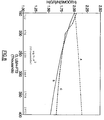
- FIG. 8 is a graph showing the relative performance of the tube of the present invention compared to two prior art tubes when the tubes are used in an evaporating application.
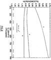
- FIG. 9 is a graph showing the relative performance of the tube of the present invention compared to two prior art tubes when the tubes are used in a condensing application.
- FIG. 1 shows, in an overall isometric view, the heat exchanger tube of the present invention.
- Tube 50 has tube wall 51 upon which is formed internal surface enhancement 52 .
- FIG. 2 depicts heat exchanger tube 50 in a cross sectioned elevation view. Only a single rib 53 of surface enhancement 52 (FIG. 1) is shown in FIG. 2 for clarity, but in the tube of the present invention, a plurality of ribs 53 , all parallel to each other, extend out from wall 51 of tube 50 . Rib 53 is inclined at angle ⁇ from tube longitudinal axis a T . Tube 50 has internal diameter, as measured from the internal surface of the tube between ribs, D2.
- FIG. 3 is an isometric view of a portion of wall 51 of heat exchanger tube 50 depicting details of surface enhancement 52 .
- Extending outward from wall 51 are a plurality of ribs 53 .
- At intervals along the ribs are a series of notches 54 .
- notches 54 are formed in ribs 53 by a rolling process.
- the material displaced as the notches are formed is left as a projection 55 that projects outward from each side of a given rib 53 around each notch 54 in that rib.
- the projections have a salutary effect on the heat transfer performance of the tube, as they both increase the surface area of the tube exposed to the fluid flowing through the tube and also promote turbulence in the fluid flow near the tube inner surface.
- FIG. 4 is a plan view of a portion of wall 51 of tube 50 .
- the figure shows ribs 53 disposed on the wall at rib spacing S r .
- Notches 54 are impressed into the ribs at notch interval S n .
- the angle of incidence between the notches and the ribs is angle ⁇ .
- FIG. 5 is a section view of wall 51 taken through line V-V in FIG. 4 .
- the figure shows that ribs 53 have height H r and have rib spacing S r .
- FIG. 6 is a section view of wall 51 taken through line VI-VI in FIG. 4 .
- the figure shows that notches 54 have an angle between opposite notch faces 56 of ⁇ and are impressed into ribs 54 to a depth of D n .
- the interval between adjacent notches is S n .
- a tube embodying the present invention and having a nominal outside diameter of 20 mm (3/4 inch) or less should have an internal enhancement with features as described above and having the following parameters:
- Enhancement 52 may be formed on the interior of tube wall 51 by any suitable process.
- an effective method is to apply the enhancement pattern by roll embossing on one surface of a metal strip before the strip is roll formed into a circular cross section and seam welded into a tube.
- FIG. 7 illustrates how this may be done.
- Two roll embossing stations respectively 10 and 20 , are positioned in the production line for roll forming and seam welding metal strip 30 into tubing between the source of supply of unworked metal strip and the portion of the production line where the strip is roll formed into a tubular shape.
- Each embossing station has a patterned enhancement roller, respectively 11 and 21 , and a backing roller, respectively 12 and 22 .
- patterned surface 13 on roller 11 is the mirror image of the axially ribbed portion of the surface enhancement in the finished tube.
- Patterned surface 23 on roller 21 has a series of raised projections that press into the ribs formed by patterned surface 13 and form the notches in the ribs in the finished tube.
- the tube is manufactured by roll embossing, roll forming and seam welding, it is likely that there will be a region along the line of the weld in the finished tube that either lacks the enhancement configuration that is present around the remainder of the tube inner circumference, due to the nature of the manufacturing process, or has a different enhancement configuration. This region of different configuration will not adversely affect the thermal or fluid flow performance of the tube in any significant way.
- the present tube offers performance advantages over prior art heat transfer tubes in both evaporating and condensing heat exchangers.
- Curve A in FIG. 8 shows the relative evaporating performance (H(GR)/H(SMOOTH) ) of the present tube compared to a tube having a smooth inner surface over a range of mass flow velocities (G,LB/H-FT2) of refrigerant through the tube.
- curve B shows the same relative performance information for a tube having longitudinal ribs but no notches
- curve C shows the same information for a typical prior art tube having helical internal ribs.
- the graph of FIG. 8 shows that the evaporating performance of the present tube is superior to both prior art tubes over a wide range of flow rates.
- curve A in FIG. 9 shows the relative condensing performance of the present tube compared to a tube having a smooth inner surface over a range of mass flow velocities of refrigerant through the tube.
- Curve B shows the same relative performance information for a longitudinally ribbed tube having no notches and curve C shows the same information for a typical helically ribbed tube.
- the graph of FIG. 9 shows that the condensing performance of the present tube is superior to both prior art tubes over a wide range of flow rates.
Landscapes
- Engineering & Computer Science (AREA)
- Physics & Mathematics (AREA)
- Thermal Sciences (AREA)
- Mechanical Engineering (AREA)
- General Engineering & Computer Science (AREA)
- Geometry (AREA)
- Chemical & Material Sciences (AREA)
- Crystallography & Structural Chemistry (AREA)
- Heat-Exchange Devices With Radiators And Conduit Assemblies (AREA)
Claims (5)
- Un tube d'échangeur de chaleur (50) ayant une paroi (51) ayant une surface interne,un diamètre interne (D₂),un axe longitudinal (aT) etune pluralité de nervures (53) formées sur cette surface interne, chacune de ces nervures ayant deux côtés opposés et une hauteur (Hr) et s'étendant sensiblement parallèlement à cet axe longitudinal, comprenant un modèle d'entailles parallèles (54) imprimées dans ces nervures (53) jusqu'à une profondeur (Dn) d'au moins 40 pourcents de cette hauteur (Hr) de nervures (53) et un angle β oblique par rapport à cet axe longitudinal, chaque entaille comprenant des première et seconde faces opposées (56) opposées et inclinées l'une par rapport à l'autre, le rapport de cette hauteur de nervure (Hr) à ce diamètre interne du tube (D₂) étant entre 0,02 et 0,04; et le rapport entre l'intervalle (Sn) entre les entailles dans une nervure et ce diamètre interne (D₂) du tube étant entre 0,025 et 0,07 caractérisé en ce que la partie de cette entaille (54) ou cette première face est le plus près de cette seconde face étant proximale à cette surface interne, et en ce qu'une projection (55) comprenant de la matière déplacée depuis une nervure (53) lorsqu'une entaille (54) est formée dans cette nervure (53), s'étend vers l'extérieur à partir de ces côtés opposés de cette nervure (53) dans le voisinage de chaque entaille (54) dans cette nervure (53).
- Le tube d'échangeur de chaleur de la revendication 1 caractérisé en ce que l'angle (γ) entre les faces opposées (56) de cette entaille (54) est inférieur à 90°.
- Le tube d'échangeur de chaleur de la revendication 1 caractérisé en ce que l'angle (β) selon lequel le modèle d'entailles intersecte ces nervures (53) est entre 20 et 90°.
- Le tube d'échangeur de chaleur selon la revendication 3 caractérisé en ce que cet angle (β) d'intersection est de 45°.
- Le tube d'échangeur de chaleur de la revendication 1 caractérisé en ce que ces nervures (53) sont disposées à des intervalles sensiblement égaux le long de cette surface interne du tube d'échangeur de chaleur.
Applications Claiming Priority (2)
| Application Number | Priority Date | Filing Date | Title |
|---|---|---|---|
| US991777 | 1992-12-16 | ||
| US07/991,777 US5332034A (en) | 1992-12-16 | 1992-12-16 | Heat exchanger tube |
Publications (2)
| Publication Number | Publication Date |
|---|---|
| EP0603108A1 EP0603108A1 (fr) | 1994-06-22 |
| EP0603108B1 true EP0603108B1 (fr) | 1996-05-15 |
Family
ID=25537552
Family Applications (1)
| Application Number | Title | Priority Date | Filing Date |
|---|---|---|---|
| EP93630097A Expired - Lifetime EP0603108B1 (fr) | 1992-12-16 | 1993-12-02 | Tube d'échangeur de chaleur |
Country Status (10)
| Country | Link |
|---|---|
| US (1) | US5332034A (fr) |
| EP (1) | EP0603108B1 (fr) |
| JP (1) | JP2534450B2 (fr) |
| KR (1) | KR0124811B1 (fr) |
| CN (1) | CN1071885C (fr) |
| BR (1) | BR9305053A (fr) |
| CA (1) | CA2110622C (fr) |
| DE (1) | DE69302668T2 (fr) |
| ES (1) | ES2087695T3 (fr) |
| MX (1) | MX9308036A (fr) |
Families Citing this family (67)
| Publication number | Priority date | Publication date | Assignee | Title |
|---|---|---|---|---|
| DE4301668C1 (de) * | 1993-01-22 | 1994-08-25 | Wieland Werke Ag | Wärmeaustauschwand, insbesondere für Sprühverdampfung |
| US6164370A (en) * | 1993-07-16 | 2000-12-26 | Olin Corporation | Enhanced heat exchange tube |
| US5458191A (en) * | 1994-07-11 | 1995-10-17 | Carrier Corporation | Heat transfer tube |
| CN1084876C (zh) * | 1994-08-08 | 2002-05-15 | 运载器有限公司 | 传热管 |
| CA2161296C (fr) * | 1994-11-17 | 1998-06-02 | Neelkanth S. Gupte | Tube de transfert thermique |
| DE69525594T2 (de) * | 1994-11-17 | 2002-08-22 | Carrier Corp., Syracuse | Wärmeaustauschrohr |
| JP3323682B2 (ja) * | 1994-12-28 | 2002-09-09 | 株式会社日立製作所 | 混合冷媒用内面クロス溝付き伝熱管 |
| DE19510124A1 (de) * | 1995-03-21 | 1996-09-26 | Km Europa Metal Ag | Austauscherrohr für einen Wärmeaustauscher |
| DE19612470A1 (de) * | 1996-03-28 | 1997-10-02 | Km Europa Metal Ag | Austauscherrohr |
| IT1283468B1 (it) * | 1996-07-19 | 1998-04-21 | Alcan Alluminio S P A | Laminato per la realizzazione di scambiatori di calore e relativo metodo di produzione |
| KR100245383B1 (ko) * | 1996-09-13 | 2000-03-02 | 정훈보 | 교차홈 형성 전열관 및 그 제조 방법 |
| US20020062944A1 (en) * | 1997-02-04 | 2002-05-30 | Richard Wisniewski | Freezing and thawing of biopharmaceuticals within a vessel having a dual flow conduit |
| US6196296B1 (en) | 1997-02-04 | 2001-03-06 | Integrated Biosystems, Inc. | Freezing and thawing vessel with thermal bridge formed between container and heat exchange member |
| US20020020516A1 (en) * | 1997-02-04 | 2002-02-21 | Richard Wisniewski | Freezing and thawing vessel with thermal bridge formed between internal structure and heat exchange member |
| CA2230213C (fr) * | 1997-03-17 | 2003-05-06 | Xin Liu | Tube de transfert de chaleur et methode de fabrication de ce tube |
| US5785088A (en) * | 1997-05-08 | 1998-07-28 | Wuh Choung Industrial Co., Ltd. | Fiber pore structure incorporate with a v-shaped micro-groove for use with heat pipes |
| JPH1118608A (ja) * | 1997-07-01 | 1999-01-26 | Matsushita Electron Corp | ペット用自動給餌システム |
| JPH1183368A (ja) * | 1997-09-17 | 1999-03-26 | Hitachi Cable Ltd | 内面溝付伝熱管 |
| US6182743B1 (en) * | 1998-11-02 | 2001-02-06 | Outokumpu Cooper Franklin Inc. | Polyhedral array heat transfer tube |
| US6176301B1 (en) * | 1998-12-04 | 2001-01-23 | Outokumpu Copper Franklin, Inc. | Heat transfer tube with crack-like cavities to enhance performance thereof |
| JP2001241877A (ja) * | 2000-02-25 | 2001-09-07 | Furukawa Electric Co Ltd:The | 内面溝付管及びその製造方法 |
| DE10041919C1 (de) | 2000-08-25 | 2001-10-31 | Wieland Werke Ag | Innenberipptes Wärmeaustauschrohr mit versetzt angeordneten Rippen unterschiedlicher Höhe |
| US6883597B2 (en) * | 2001-04-17 | 2005-04-26 | Wolverine Tube, Inc. | Heat transfer tube with grooved inner surface |
| US6635414B2 (en) | 2001-05-22 | 2003-10-21 | Integrated Biosystems, Inc. | Cryopreservation system with controlled dendritic freezing front velocity |
| US6684646B2 (en) * | 2001-05-22 | 2004-02-03 | Integrated Biosystems, Inc. | Systems and methods for freezing, storing and thawing biopharmaceutical material |
| US6698213B2 (en) * | 2001-05-22 | 2004-03-02 | Integrated Biosystems, Inc. | Systems and methods for freezing and storing biopharmaceutical material |
| US6945056B2 (en) * | 2001-11-01 | 2005-09-20 | Integrated Biosystems, Inc. | Systems and methods for freezing, mixing and thawing biopharmaceutical material |
| US7104074B2 (en) * | 2001-11-01 | 2006-09-12 | Integrated Biosystems, Inc. | Systems and methods for freezing, storing, transporting and thawing biopharmaceutical material |
| DE10156374C1 (de) * | 2001-11-16 | 2003-02-27 | Wieland Werke Ag | Beidseitig strukturiertes Wärmeaustauscherrohr und Verfahren zu dessen Herstellung |
| US6938688B2 (en) * | 2001-12-05 | 2005-09-06 | Thomas & Betts International, Inc. | Compact high efficiency clam shell heat exchanger |
| FR2837270B1 (fr) * | 2002-03-12 | 2004-10-01 | Trefimetaux | Tubes rainures a utilisation reversible pour echangeurs thermiques |
| YU12904A (sh) | 2002-06-10 | 2005-09-19 | Wolverine Tube Inc. | Cev za prenos toplote i postupak i alat za njenu proizvodnju |
| US8573022B2 (en) * | 2002-06-10 | 2013-11-05 | Wieland-Werke Ag | Method for making enhanced heat transfer surfaces |
| US7311137B2 (en) * | 2002-06-10 | 2007-12-25 | Wolverine Tube, Inc. | Heat transfer tube including enhanced heat transfer surfaces |
| US20040099409A1 (en) * | 2002-11-25 | 2004-05-27 | Bennett Donald L. | Polyhedral array heat transfer tube |
| CN1781196A (zh) | 2003-04-04 | 2006-05-31 | 瓦伊金技术有限公司 | 一种智能材料致动器功的最佳化装置和方法 |
| US20060112535A1 (en) | 2004-05-13 | 2006-06-01 | Petur Thors | Retractable finning tool and method of using |
| EP1644682A1 (fr) * | 2003-07-15 | 2006-04-12 | Outokumpu Copper Products Oy | Tube de transfert thermique sous pression et son procede de fabrication |
| CN1595042B (zh) * | 2003-09-11 | 2010-05-12 | 武汉宏图高炉热风炉高新技术研究所 | 一种热交换器强化换热装置 |
| ITTO20030724A1 (it) * | 2003-09-19 | 2005-03-20 | Dayco Fuel Man Spa | Dispositivo di raffreddamento per un circuito di riciclo di carburante da un sistema di iniezione a un serbatoio di un autoveicolo |
| EP1692447B1 (fr) * | 2003-10-23 | 2009-06-17 | Wolverine Tube, Inc. | Procede et outil de fabrication de surfaces d'echange thermique ameliorees |
| DE102004038182A1 (de) * | 2004-08-06 | 2006-03-16 | Daimlerchrysler Ag | Verfahren zum spanabhebenden Bearbeiten von thermisch gespritzten Zylinderlaufbahnen |
| ES2389664T3 (es) * | 2005-03-25 | 2012-10-30 | Wolverine Tube, Inc. | Herramienta para hacer superficies con mejor transferencia de calor |
| US20070137842A1 (en) * | 2005-12-20 | 2007-06-21 | Philippe Lam | Heating and cooling system for biological materials |
| WO2007103917A2 (fr) * | 2006-03-06 | 2007-09-13 | Integrated Biosystems, Inc. | Systèmes et procédés utilisés pour congeler, stocker et décongeler des matières biopharmaceutiques |
| US20080078534A1 (en) * | 2006-10-02 | 2008-04-03 | General Electric Company | Heat exchanger tube with enhanced heat transfer co-efficient and related method |
| US20090095368A1 (en) * | 2007-10-10 | 2009-04-16 | Baker Hughes Incorporated | High friction interface for improved flow and method |
| TW200940198A (en) * | 2008-03-27 | 2009-10-01 | Rachata Leelaprachakul | Processes for textured pipe manufacturer |
| JP5399472B2 (ja) * | 2008-04-18 | 2014-01-29 | ヴィーランド―ヴェルケ エージー | 凝縮用および蒸発用フィン付き管 |
| US8997846B2 (en) | 2008-10-20 | 2015-04-07 | The Government Of The United States Of America, As Represented By The Secretary Of The Navy | Heat dissipation system with boundary layer disruption |
| JP5435460B2 (ja) * | 2009-05-28 | 2014-03-05 | 古河電気工業株式会社 | 伝熱管 |
| US8875780B2 (en) * | 2010-01-15 | 2014-11-04 | Rigidized Metals Corporation | Methods of forming enhanced-surface walls for use in apparatae for performing a process, enhanced-surface walls, and apparatae incorporating same |
| AU2010341861B2 (en) | 2010-01-15 | 2015-04-23 | Rigidized Metals Corporation | Methods of forming enhanced-surface walls for use in apparatae |
| JP2012083006A (ja) * | 2010-10-08 | 2012-04-26 | Furukawa Electric Co Ltd:The | 伝熱管及びその製造方法並びにその製造装置 |
| WO2012060461A1 (fr) * | 2010-11-02 | 2012-05-10 | 日本電気株式会社 | Dispositif de refroidissement et son procédé de fabrication |
| US8613308B2 (en) | 2010-12-10 | 2013-12-24 | Uop Llc | Process for transferring heat or modifying a tube in a heat exchanger |
| US20130299145A1 (en) * | 2012-04-19 | 2013-11-14 | National University Of Singapore | Heat sink system |
| WO2014160565A1 (fr) * | 2013-03-26 | 2014-10-02 | United Technologies Corporation | Moteur à turbine et composant de moteur à turbine ayant des pieds de refroidissement perfectionnés |
| US10551130B2 (en) * | 2014-10-06 | 2020-02-04 | Brazeway, Inc. | Heat transfer tube with multiple enhancements |
| US10900722B2 (en) | 2014-10-06 | 2021-01-26 | Brazeway, Inc. | Heat transfer tube with multiple enhancements |
| DE102016006913B4 (de) * | 2016-06-01 | 2019-01-03 | Wieland-Werke Ag | Wärmeübertragerrohr |
| DE102016006914B4 (de) * | 2016-06-01 | 2019-01-24 | Wieland-Werke Ag | Wärmeübertragerrohr |
| DE102016006967B4 (de) * | 2016-06-01 | 2018-12-13 | Wieland-Werke Ag | Wärmeübertragerrohr |
| USD1009227S1 (en) | 2016-08-05 | 2023-12-26 | Rls Llc | Crimp fitting for joining tubing |
| JP7474577B2 (ja) * | 2019-10-23 | 2024-04-25 | 株式会社Uacj | 伝熱二重管、伝熱二重管用内管及びその製造方法 |
| PL4164821T3 (pl) * | 2020-06-15 | 2025-10-06 | Hydro Extruded Solutions As | Walec wytłaczający |
| JP6868146B1 (ja) * | 2020-06-29 | 2021-05-12 | 株式会社クボタ | 流体撹拌要素を具える熱分解管 |
Family Cites Families (17)
| Publication number | Priority date | Publication date | Assignee | Title |
|---|---|---|---|---|
| US3273599A (en) * | 1966-09-20 | Internally finned condenser tube | ||
| US3326283A (en) * | 1965-03-29 | 1967-06-20 | Trane Co | Heat transfer surface |
| US3861462A (en) * | 1971-12-30 | 1975-01-21 | Olin Corp | Heat exchange tube |
| US3885622A (en) * | 1971-12-30 | 1975-05-27 | Olin Corp | Heat exchanger tube |
| JPS5813837B2 (ja) * | 1978-05-15 | 1983-03-16 | 古河電気工業株式会社 | 凝縮伝熱管 |
| JPS6011800B2 (ja) * | 1978-05-31 | 1985-03-28 | 株式会社神戸製鋼所 | 凝縮伝熱管の製造法 |
| JPS5659194A (en) * | 1979-10-20 | 1981-05-22 | Daikin Ind Ltd | Heat transfer tube |
| JPS6029593A (ja) * | 1983-07-27 | 1985-02-14 | Hitachi Ltd | 単相流伝熱管構造 |
| JPS60142195A (ja) * | 1983-12-28 | 1985-07-27 | Hitachi Cable Ltd | 内面溝付伝熱管 |
| JPS6189497A (ja) * | 1984-10-05 | 1986-05-07 | Hitachi Ltd | 伝熱管 |
| US4733698A (en) * | 1985-09-13 | 1988-03-29 | Kabushiki Kaisha Kobe Seiko Sho | Heat transfer pipe |
| JPS62142995A (ja) * | 1985-12-17 | 1987-06-26 | Hitachi Cable Ltd | 内面らせん溝付伝熱管 |
| JP2580353B2 (ja) * | 1990-01-09 | 1997-02-12 | 三菱重工業株式会社 | 電縫伝熱管とその製造方法 |
| US5052476A (en) * | 1990-02-13 | 1991-10-01 | 501 Mitsubishi Shindoh Co., Ltd. | Heat transfer tubes and method for manufacturing |
| JPH043892A (ja) * | 1990-04-19 | 1992-01-08 | Hitachi Cable Ltd | 伝熱管の製造方法 |
| US5070937A (en) * | 1991-02-21 | 1991-12-10 | American Standard Inc. | Internally enhanced heat transfer tube |
| JPH0579783A (ja) * | 1991-06-11 | 1993-03-30 | Sumitomo Light Metal Ind Ltd | 内面溝付伝熱管 |
-
1992
- 1992-12-16 US US07/991,777 patent/US5332034A/en not_active Expired - Lifetime
-
1993
- 1993-12-02 EP EP93630097A patent/EP0603108B1/fr not_active Expired - Lifetime
- 1993-12-02 DE DE69302668T patent/DE69302668T2/de not_active Expired - Lifetime
- 1993-12-02 ES ES93630097T patent/ES2087695T3/es not_active Expired - Lifetime
- 1993-12-03 CA CA002110622A patent/CA2110622C/fr not_active Expired - Fee Related
- 1993-12-14 BR BR9305053A patent/BR9305053A/pt not_active IP Right Cessation
- 1993-12-15 MX MX9308036A patent/MX9308036A/es unknown
- 1993-12-15 CN CN93120442A patent/CN1071885C/zh not_active Expired - Fee Related
- 1993-12-15 JP JP5314637A patent/JP2534450B2/ja not_active Expired - Fee Related
- 1993-12-15 KR KR1019930027774A patent/KR0124811B1/ko not_active Expired - Fee Related
Also Published As
| Publication number | Publication date |
|---|---|
| ES2087695T3 (es) | 1996-07-16 |
| DE69302668T2 (de) | 1996-09-26 |
| JPH06221788A (ja) | 1994-08-12 |
| CN1094157A (zh) | 1994-10-26 |
| CN1071885C (zh) | 2001-09-26 |
| JP2534450B2 (ja) | 1996-09-18 |
| KR0124811B1 (ko) | 1997-12-23 |
| CA2110622C (fr) | 1996-12-31 |
| US5332034A (en) | 1994-07-26 |
| BR9305053A (pt) | 1994-06-21 |
| EP0603108A1 (fr) | 1994-06-22 |
| KR940015451A (ko) | 1994-07-21 |
| DE69302668D1 (de) | 1996-06-20 |
| MX9308036A (es) | 1994-06-30 |
| CA2110622A1 (fr) | 1994-06-17 |
Similar Documents
| Publication | Publication Date | Title |
|---|---|---|
| EP0603108B1 (fr) | Tube d'échangeur de chaleur | |
| EP0692694A2 (fr) | Tube de transfer de chaleur | |
| US6182743B1 (en) | Polyhedral array heat transfer tube | |
| US5975196A (en) | Heat transfer tube | |
| EP0644392B1 (fr) | Tube d'échangeur de chaleur | |
| EP0591094A1 (fr) | Tube de transfert thermique cannelé vers l'intérieur | |
| JPH109789A (ja) | 熱交換管 | |
| US6176301B1 (en) | Heat transfer tube with crack-like cavities to enhance performance thereof | |
| US10267573B2 (en) | Polyhedral array heat transfer tube | |
| US5931226A (en) | Refrigerant tubes for heat exchangers | |
| EP0762070B1 (fr) | Tubes de refroidissement pour échangeurs de chaleur | |
| US20030168209A1 (en) | Heat transfer tube with ribbed inner surface | |
| KR940010977B1 (ko) | 열교환기용 전열관 | |
| EP0881008A2 (fr) | Procédé de fabrication de tubes de refroidissement pour échangeurs de chaleur | |
| MXPA01004379A (en) | Polyhedral array heat transfer tube | |
| JPH03169441A (ja) | 伝熱管およびその製造方法 |
Legal Events
| Date | Code | Title | Description |
|---|---|---|---|
| PUAI | Public reference made under article 153(3) epc to a published international application that has entered the european phase |
Free format text: ORIGINAL CODE: 0009012 |
|
| AK | Designated contracting states |
Kind code of ref document: A1 Designated state(s): DE ES FR IT |
|
| 17P | Request for examination filed |
Effective date: 19940627 |
|
| 17Q | First examination report despatched |
Effective date: 19950718 |
|
| GRAH | Despatch of communication of intention to grant a patent |
Free format text: ORIGINAL CODE: EPIDOS IGRA |
|
| GRAA | (expected) grant |
Free format text: ORIGINAL CODE: 0009210 |
|
| AK | Designated contracting states |
Kind code of ref document: B1 Designated state(s): DE ES FR IT |
|
| ET | Fr: translation filed | ||
| REG | Reference to a national code |
Ref country code: ES Ref legal event code: BA2A Ref document number: 2087695 Country of ref document: ES Kind code of ref document: T3 |
|
| REF | Corresponds to: |
Ref document number: 69302668 Country of ref document: DE Date of ref document: 19960620 |
|
| REG | Reference to a national code |
Ref country code: ES Ref legal event code: FG2A Ref document number: 2087695 Country of ref document: ES Kind code of ref document: T3 |
|
| ITF | It: translation for a ep patent filed | ||
| PLBE | No opposition filed within time limit |
Free format text: ORIGINAL CODE: 0009261 |
|
| STAA | Information on the status of an ep patent application or granted ep patent |
Free format text: STATUS: NO OPPOSITION FILED WITHIN TIME LIMIT |
|
| 26N | No opposition filed | ||
| PGFP | Annual fee paid to national office [announced via postgrant information from national office to epo] |
Ref country code: ES Payment date: 20071211 Year of fee payment: 15 |
|
| REG | Reference to a national code |
Ref country code: ES Ref legal event code: FD2A Effective date: 20081203 |
|
| PG25 | Lapsed in a contracting state [announced via postgrant information from national office to epo] |
Ref country code: ES Free format text: LAPSE BECAUSE OF NON-PAYMENT OF DUE FEES Effective date: 20081203 |
|
| PGFP | Annual fee paid to national office [announced via postgrant information from national office to epo] |
Ref country code: IT Payment date: 20091216 Year of fee payment: 17 Ref country code: FR Payment date: 20091215 Year of fee payment: 17 |
|
| PGFP | Annual fee paid to national office [announced via postgrant information from national office to epo] |
Ref country code: DE Payment date: 20091230 Year of fee payment: 17 |
|
| REG | Reference to a national code |
Ref country code: FR Ref legal event code: ST Effective date: 20110831 |
|
| PG25 | Lapsed in a contracting state [announced via postgrant information from national office to epo] |
Ref country code: FR Free format text: LAPSE BECAUSE OF NON-PAYMENT OF DUE FEES Effective date: 20110103 |
|
| PG25 | Lapsed in a contracting state [announced via postgrant information from national office to epo] |
Ref country code: DE Free format text: LAPSE BECAUSE OF NON-PAYMENT OF DUE FEES Effective date: 20110701 |
|
| PG25 | Lapsed in a contracting state [announced via postgrant information from national office to epo] |
Ref country code: IT Free format text: LAPSE BECAUSE OF NON-PAYMENT OF DUE FEES Effective date: 20101202 |
|
| REG | Reference to a national code |
Ref country code: DE Ref legal event code: R119 Ref document number: 69302668 Country of ref document: DE Effective date: 20110701 |