EP0603141A1 - Réservoir d'huile - Google Patents
Réservoir d'huile Download PDFInfo
- Publication number
- EP0603141A1 EP0603141A1 EP93850202A EP93850202A EP0603141A1 EP 0603141 A1 EP0603141 A1 EP 0603141A1 EP 93850202 A EP93850202 A EP 93850202A EP 93850202 A EP93850202 A EP 93850202A EP 0603141 A1 EP0603141 A1 EP 0603141A1
- Authority
- EP
- European Patent Office
- Prior art keywords
- valve
- container
- flange
- neck portion
- annular groove
- Prior art date
- Legal status (The legal status is an assumption and is not a legal conclusion. Google has not performed a legal analysis and makes no representation as to the accuracy of the status listed.)
- Granted
Links
- 239000000314 lubricant Substances 0.000 title claims abstract description 28
- 230000001050 lubricating effect Effects 0.000 claims abstract description 5
- 238000010008 shearing Methods 0.000 claims abstract description 4
- 238000005461 lubrication Methods 0.000 description 18
- 239000004519 grease Substances 0.000 description 7
- 239000002184 metal Substances 0.000 description 5
- 230000001419 dependent effect Effects 0.000 description 2
- 239000000463 material Substances 0.000 description 2
- 230000007246 mechanism Effects 0.000 description 2
- 210000002445 nipple Anatomy 0.000 description 2
- 230000004913 activation Effects 0.000 description 1
- 230000007797 corrosion Effects 0.000 description 1
- 238000005260 corrosion Methods 0.000 description 1
- 238000006073 displacement reaction Methods 0.000 description 1
- 230000000694 effects Effects 0.000 description 1
- 230000001771 impaired effect Effects 0.000 description 1
- 238000003801 milling Methods 0.000 description 1
- 230000001681 protective effect Effects 0.000 description 1
- 238000005096 rolling process Methods 0.000 description 1
- 239000002699 waste material Substances 0.000 description 1
Images

Classifications
-
- F—MECHANICAL ENGINEERING; LIGHTING; HEATING; WEAPONS; BLASTING
- F16—ENGINEERING ELEMENTS AND UNITS; GENERAL MEASURES FOR PRODUCING AND MAINTAINING EFFECTIVE FUNCTIONING OF MACHINES OR INSTALLATIONS; THERMAL INSULATION IN GENERAL
- F16N—LUBRICATING
- F16N11/00—Arrangements for supplying grease from a stationary reservoir or the equivalent in or on the machine or member to be lubricated; Grease cups
- F16N11/04—Spring-loaded devices
-
- F—MECHANICAL ENGINEERING; LIGHTING; HEATING; WEAPONS; BLASTING
- F16—ENGINEERING ELEMENTS AND UNITS; GENERAL MEASURES FOR PRODUCING AND MAINTAINING EFFECTIVE FUNCTIONING OF MACHINES OR INSTALLATIONS; THERMAL INSULATION IN GENERAL
- F16N—LUBRICATING
- F16N21/00—Conduits; Junctions; Fittings for lubrication apertures
-
- F—MECHANICAL ENGINEERING; LIGHTING; HEATING; WEAPONS; BLASTING
- F16—ENGINEERING ELEMENTS AND UNITS; GENERAL MEASURES FOR PRODUCING AND MAINTAINING EFFECTIVE FUNCTIONING OF MACHINES OR INSTALLATIONS; THERMAL INSULATION IN GENERAL
- F16N—LUBRICATING
- F16N2270/00—Controlling
- F16N2270/50—Condition
- F16N2270/56—Temperature
Definitions
- Apparatuses for automatic lubrication of cooperating surfaces at different mechanical mechanisms are well-known since long and they operate to provide, according to certain predetermined parameters, a lubricant film, which prevents direct metallic contact between the cooperating surfaces of the mechanism and which furthermore has for a purpose to protect against wear and corrosion.
- the volume of lubricant needed for the lubrication in each specific case thereby is often decided from experience, and the lubricant automaton is set to discharge a desired quantity of lubricant.
- grease is advantageous as lubricant and the automatons intended for such lubrication often consist of a valve, through which the lubricant is discharged, and a container connectable to the valve, which container has an internal piston driven by a spring or possibly via a diaphragm by means of an electrolytically generated driving gas.
- valve and the container commonly are manufactured as separate units, but they generally have been assembled in such a manner, that the entire lubricant container with valve has been discarded when the grease in the container has been consumed.
- SE-C-8702597-9 describes an apparatus for automatic grease lubrication of bearings, wherein the valve is equipped with an element adapted to sense the heat development at the bearing position and to cause a reduction of the lubricant feed, when a predetermined temperature level is exceeded.
- the heat sensing and heat actuatable element then is constituted by a memory metal spring, which acts to reduce and/or completely close the discharge opening of the valve, when the temperature at the bearing position raises above a certain level, and this apparatus gives a satisfactory feed-out quantity, well adapted to the heat development.
- valve part and the container of the apparatus according to the above mentioned patent can be taken apart, but a parting of the valve body and the container and subsequent mounting of a new container means a circumstantial and particularly in small spaces troublesome work which is hardly rational.
- the purpose of the present invention is to eliminate the above mentioned drawbacks at a lubricant container for a lubricating apparatus, of the type where the container is intended to be interconnected with and cooperate with a valve adapted to govern the advance feed motion of a discharge device present in the container, and this is achieved in that the lubricant container is equipped with a gable having a substantially tubular neck portion intended to receive a portion of the valve, which can be pushed thereinto, whereby a radially circumferential flange is provided in the neck portion, which flange is adapted to engage in interconnection position into an annular groove on the envelope surface of the valve, whereby the annular groove and the flange are situated at such a distance from one end of the valve, and from the free end of the neck portion resp, that seat portions present in the neck portion and in the valve sealingly engage against each other in said interconnection position, and that the annular groove and flange are designed thus, that the flange, when the valve is pushed in its longitudinal direction into the
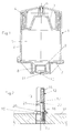
- Fig. 1 shows a lubricant container according to the invention in a central vertical section.
- Fig. 2 shows in a partial cross section a valve part mounted in a seat and intended to be connected to a lubricant container according to Fig. 1, for forming a lubrication apparatus.
- Fig.s 3-5 show in views corresponding to Fig. 1 assembly of the lubrication apparatus, activation thereof and removal of an emptied container, resp.
- Fig. 6 shows a partial enlargement of a portion of the lower part of the container following its disassembly from the valve.
- Fig. 1 shows in an axial section a lubrication container 1 according to the invention, which incorporates a preferably cylindrical housing 2, having a closed top and in which is provided an axially displaceable piston 3.
- the piston is acted upon by a force acting between the piston and the upper part of the housing, said force here represented by a helical spring 4, which strives to press the piston downwards against lubricant present in the interior 5 of the container.
- a transport lock 6 in the form of a screw.
- a gable 7 At the lower end of the housing 2, this is closed by a gable 7 with a centrally located tubular neck portion 8 projecting from the container and intended to be connected to a valve part, and which at its side facing the interior of the container being equipped with a radial circumferential flange 9.
- the circular channel through the neck-shaped portion, at its side turned away from the container is provided with a first and a second shoulder 10 and 11 resp., extending from the outside and inwards, and acting as seats for the valve to be mounted therein.
- the channel through the neck-shaped portion In transport position the channel through the neck-shaped portion is preferably closed by means of a not further shown protective cap, adapted to be inserted into the first shoulder 10, and which is manually removed before the container is connected to the valve.
- Fig. 2 shows, partially in a vertical section, an embodiment of a valve 12, intended to be connected to the lubricant container 1 according to Fig. 1, and which in the case shown is of the kind incorporating a sleeve shaped body 13 internally provided with a valve body 16, which is axially moveable and which is clamped between a first and a second spring 14, 15, said valve body being adapted to close radial discharge openings 17 provided in the sleeve-shaped body 13, when this is positioned in its upper (not shown) setting position.
- the second, lower spring 15 thereby is preferably made from a so called memory metal, whereas the first, upper spring 14 creates a counter-force against the memory metal spring, in order to balance the activity area of this.
- valve is described in detail in the above mentioned SE-C-8702597-9 and it constitutes no actual part of the invention itself, which can be used also with a valve in form of a simple restriction, even if this gives no adjustability dependent of temperature changes at the position of lubrication.
- the valve is screwed in through a wall 18 on the opposite side of which the lubrication shall be effected and it rests with a circumferential flange 19 against the surface of the wall.
- the flange 19 at its side turned away from the wall is adapted to be received in the first shoulder 10 in the neck-shaped portion 8 of the lubricant container, and it is intended to be mounted with an O-ring 20 located about the periphery of the body 13 against the upper surface of the flange 10, and this O-ring is dimensioned sealingly to engage the second shoulder 11 in the container 1, when valve and container are joined together.
- annular groove 21 Spaced apart from the upper side of the flange 19 in the valve a distance corresponding to the distance between the first shoulder 10 in the neck-shaped portion 8 of the container and the radially inwardly directed flange 9 thereof, there is provided at the periphery of the valve body an annular groove 21 with a circumferential chamfering 22 situated thereabove and extending downwards/outwards.
- the radially inwardly directed flange 9 in the neck-portion of the container is provided with a chamfering on its side turned away from the container, whereas its side facing the container is straight.
- Fig. 3 is shown schematically how container 1 and valve 12 can be put together in a very simple manner.
- the lubricant container 1 hereby is positioned with its neck-shaped portion 8 in the gable 7 thereof just above the valve body 13 which is screwed into a wall 18, whereupon the container manually is pushed down, thus that the valve flange and O-ring 20 will engage the seats 10 and 11 resp.in the container (see Fig. 1), whereby simultaneously the flange-shaped radial portion 9 by sliding against the valve shoulder 22 will snap into the groove 21 on the valve, which results in an interlocking of the valve and the container in a position where the very fine slit between the valve and the neck-shaped container portion is sealed off as the O-ring 20 is clamped therebetween.
- the snap-locking of the flange 9 into the annular groove is facilitated by the chamfering on the side of the flange turned away from the container.
- Fig. 4 is shown how the lubricating apparatus constituted by the container and valve thus assembled is activated by the transport lock 6 being unscrewed thus that the driving spring 4 or the like can begin displacing the piston 3 and thereby bring about a slow discharge of the lubrican, whereby the discharge rate in the case shown, is governed by the thermal responsive valve.
- a spanner 23 belonging to the lubricating apparatus is used, which spanner is introduced around the circumferential flange 19 of the valve, and which during breaking upwards (as shown with the arrow in Fig. 5) is urged to press against the end surface of the neck portion 8 of the container.
- the flange 9 projecting radially inwardly from the neck portion 8 of the container at its straight inner side facing the container will be subjected to a shearing force against the straight upper edge of the annular groove 21, which results in the flange being sheared off from the neck portion 8 and the emptied container 1 coming loose from the valve.
- Fig. 6 is shown in bigger scale and in cross section a part of the neck portion 8 of the emptied container, now removed from the valve and with its inner wall from which the flange 9 has been sheared off at 24.
- the lubricant container according to the invention has been shown in the accompanying drawings and described in connection thereto together with a valve with temperature dependent governing by means of memory metal spring, but the lubricant container may of course also be used with another type of valve and even with a valve only in the form of a simple restriction, even if the saving will be less in that case.
- valve screwed directly into a wall of the lubrication spot and with the container positioned in alignment with the valve screwed into the wall, but in positions difficult to reach, the valve may of course be located spaced apart from the wall of the lubrication spot and via a hose and a nipple be connected thereto, and it is also imaginable to have a valve with an angled attachment nipple, which provides a possibility of mounting the container even in parallel with the wall of the lubrication spot.
Landscapes
- Engineering & Computer Science (AREA)
- General Engineering & Computer Science (AREA)
- Mechanical Engineering (AREA)
- Closures For Containers (AREA)
- Temperature-Responsive Valves (AREA)
Applications Claiming Priority (2)
| Application Number | Priority Date | Filing Date | Title |
|---|---|---|---|
| SE9203380 | 1992-11-13 | ||
| SE9203380A SE9203380L (sv) | 1992-11-13 | 1992-11-13 | Smörjmedelsbehållare med automatisk utmatning |
Publications (2)
| Publication Number | Publication Date |
|---|---|
| EP0603141A1 true EP0603141A1 (fr) | 1994-06-22 |
| EP0603141B1 EP0603141B1 (fr) | 1997-01-22 |
Family
ID=20387784
Family Applications (1)
| Application Number | Title | Priority Date | Filing Date |
|---|---|---|---|
| EP93850202A Expired - Lifetime EP0603141B1 (fr) | 1992-11-13 | 1993-10-27 | Réservoir d'huile |
Country Status (5)
| Country | Link |
|---|---|
| US (1) | US5449050A (fr) |
| EP (1) | EP0603141B1 (fr) |
| JP (1) | JPH0781675B2 (fr) |
| DE (1) | DE69307670T2 (fr) |
| SE (1) | SE9203380L (fr) |
Cited By (1)
| Publication number | Priority date | Publication date | Assignee | Title |
|---|---|---|---|---|
| WO2001071240A1 (fr) * | 2000-03-21 | 2001-09-27 | Wymark Limited | Dispositif de lubirification |
Families Citing this family (2)
| Publication number | Priority date | Publication date | Assignee | Title |
|---|---|---|---|---|
| AU6167698A (en) | 1997-02-26 | 1998-09-18 | Bijur Lubricating Corporation | Positive displacement pump |
| DE202006012999U1 (de) * | 2006-08-24 | 2007-12-27 | Willy Vogel Ag | Schmierstoffbehälter mit arretierbarer Nachführeinrichtung |
Citations (2)
| Publication number | Priority date | Publication date | Assignee | Title |
|---|---|---|---|---|
| EP0155329A1 (fr) * | 1984-03-13 | 1985-09-25 | VAW Folien-Verarbeitung GmbH | Bague de sécurité pour la protection des fermetures métalliques pour bouteilles et récipients à goulot large ou similaires |
| EP0297064A2 (fr) * | 1987-06-23 | 1988-12-28 | Skf Mekanprodukter Ab | Appareil de graissage pour paliers |
Family Cites Families (2)
| Publication number | Priority date | Publication date | Assignee | Title |
|---|---|---|---|---|
| US492091A (en) * | 1893-02-21 | Edmund h | ||
| CH87627A (fr) * | 1920-03-06 | 1921-01-03 | F A Petitpierre | Graisseur. |
-
1992
- 1992-11-13 SE SE9203380A patent/SE9203380L/ not_active IP Right Cessation
-
1993
- 1993-10-27 EP EP93850202A patent/EP0603141B1/fr not_active Expired - Lifetime
- 1993-10-27 DE DE69307670T patent/DE69307670T2/de not_active Expired - Fee Related
- 1993-11-08 US US08/148,560 patent/US5449050A/en not_active Expired - Fee Related
- 1993-11-12 JP JP5306059A patent/JPH0781675B2/ja not_active Expired - Fee Related
Patent Citations (2)
| Publication number | Priority date | Publication date | Assignee | Title |
|---|---|---|---|---|
| EP0155329A1 (fr) * | 1984-03-13 | 1985-09-25 | VAW Folien-Verarbeitung GmbH | Bague de sécurité pour la protection des fermetures métalliques pour bouteilles et récipients à goulot large ou similaires |
| EP0297064A2 (fr) * | 1987-06-23 | 1988-12-28 | Skf Mekanprodukter Ab | Appareil de graissage pour paliers |
Cited By (3)
| Publication number | Priority date | Publication date | Assignee | Title |
|---|---|---|---|---|
| WO2001071240A1 (fr) * | 2000-03-21 | 2001-09-27 | Wymark Limited | Dispositif de lubirification |
| US6802394B2 (en) | 2000-03-21 | 2004-10-12 | Wymark Limited | Lubricating device |
| AU2001240827B2 (en) * | 2000-03-21 | 2004-12-02 | Wymark Limited | A lubricating device |
Also Published As
| Publication number | Publication date |
|---|---|
| SE470141B (sv) | 1993-11-15 |
| US5449050A (en) | 1995-09-12 |
| JPH0781675B2 (ja) | 1995-09-06 |
| JPH06213391A (ja) | 1994-08-02 |
| SE9203380D0 (sv) | 1992-11-13 |
| SE9203380L (sv) | 1993-11-15 |
| DE69307670D1 (de) | 1997-03-06 |
| EP0603141B1 (fr) | 1997-01-22 |
| DE69307670T2 (de) | 1997-06-05 |
Similar Documents
| Publication | Publication Date | Title |
|---|---|---|
| US5794660A (en) | Valves for pressurized containers | |
| US4125176A (en) | Injection type lubricating apparatus | |
| EP0603141B1 (fr) | Réservoir d'huile | |
| US4611624A (en) | Line piercing valve assembly | |
| EP0140447A3 (fr) | Distributeur du type à pompe | |
| US4886144A (en) | Lubricating apparatus for bearings | |
| US3026387A (en) | Lubricant pressure control valve | |
| US4105095A (en) | Injection lubricating apparatus | |
| US4454982A (en) | Control valve | |
| US20240183490A1 (en) | Machine lubrication system | |
| US4126553A (en) | Hydraulic filter and valve arrangement | |
| EP0613540A1 (fr) | Distributeur. | |
| US4699250A (en) | Lubricant dispenser | |
| US5725073A (en) | Fluid metering device and compressed air lubricator including same | |
| CA1044160A (fr) | Capsule de graissage | |
| EP0950844B1 (fr) | Mécanisme de position zéro pour un dispositif actionné par pression de fluide | |
| EP1375040B1 (fr) | Ressort à gaz | |
| US4291785A (en) | Oil metering apparatus for air line lubricators | |
| US4892171A (en) | Adapter for use with a lubrication fitting | |
| US5117773A (en) | Device for the lubrication of the rotating hook in a sewing machine | |
| JPS625785Y2 (fr) | ||
| US3126912A (en) | Diaphragm valve having a safety shut-off means | |
| JPH0741956Y2 (ja) | オートテンショナ | |
| US384762A (en) | Petee d | |
| SU985495A1 (ru) | Вертикальна направл юща |
Legal Events
| Date | Code | Title | Description |
|---|---|---|---|
| PUAI | Public reference made under article 153(3) epc to a published international application that has entered the european phase |
Free format text: ORIGINAL CODE: 0009012 |
|
| AK | Designated contracting states |
Kind code of ref document: A1 Designated state(s): DE FR GB IT |
|
| 17P | Request for examination filed |
Effective date: 19940811 |
|
| 17Q | First examination report despatched |
Effective date: 19950406 |
|
| GRAG | Despatch of communication of intention to grant |
Free format text: ORIGINAL CODE: EPIDOS AGRA |
|
| GRAH | Despatch of communication of intention to grant a patent |
Free format text: ORIGINAL CODE: EPIDOS IGRA |
|
| GRAH | Despatch of communication of intention to grant a patent |
Free format text: ORIGINAL CODE: EPIDOS IGRA |
|
| GRAA | (expected) grant |
Free format text: ORIGINAL CODE: 0009210 |
|
| AK | Designated contracting states |
Kind code of ref document: B1 Designated state(s): DE FR GB IT |
|
| ET | Fr: translation filed | ||
| REF | Corresponds to: |
Ref document number: 69307670 Country of ref document: DE Date of ref document: 19970306 |
|
| ITF | It: translation for a ep patent filed | ||
| PLBE | No opposition filed within time limit |
Free format text: ORIGINAL CODE: 0009261 |
|
| STAA | Information on the status of an ep patent application or granted ep patent |
Free format text: STATUS: NO OPPOSITION FILED WITHIN TIME LIMIT |
|
| 26N | No opposition filed | ||
| REG | Reference to a national code |
Ref country code: GB Ref legal event code: IF02 |
|
| PGFP | Annual fee paid to national office [announced via postgrant information from national office to epo] |
Ref country code: FR Payment date: 20051017 Year of fee payment: 13 |
|
| PGFP | Annual fee paid to national office [announced via postgrant information from national office to epo] |
Ref country code: GB Payment date: 20051019 Year of fee payment: 13 |
|
| PGFP | Annual fee paid to national office [announced via postgrant information from national office to epo] |
Ref country code: DE Payment date: 20051130 Year of fee payment: 13 |
|
| PGFP | Annual fee paid to national office [announced via postgrant information from national office to epo] |
Ref country code: IT Payment date: 20061031 Year of fee payment: 14 |
|
| PG25 | Lapsed in a contracting state [announced via postgrant information from national office to epo] |
Ref country code: DE Free format text: LAPSE BECAUSE OF NON-PAYMENT OF DUE FEES Effective date: 20070501 |
|
| GBPC | Gb: european patent ceased through non-payment of renewal fee |
Effective date: 20061027 |
|
| REG | Reference to a national code |
Ref country code: FR Ref legal event code: ST Effective date: 20070629 |
|
| PG25 | Lapsed in a contracting state [announced via postgrant information from national office to epo] |
Ref country code: GB Free format text: LAPSE BECAUSE OF NON-PAYMENT OF DUE FEES Effective date: 20061027 |
|
| PG25 | Lapsed in a contracting state [announced via postgrant information from national office to epo] |
Ref country code: FR Free format text: LAPSE BECAUSE OF NON-PAYMENT OF DUE FEES Effective date: 20061031 |
|
| PG25 | Lapsed in a contracting state [announced via postgrant information from national office to epo] |
Ref country code: IT Free format text: LAPSE BECAUSE OF NON-PAYMENT OF DUE FEES Effective date: 20071027 |