EP0603635A2 - Time multiplex transmission system with propagation time compensation - Google Patents
Time multiplex transmission system with propagation time compensation Download PDFInfo
- Publication number
- EP0603635A2 EP0603635A2 EP93119729A EP93119729A EP0603635A2 EP 0603635 A2 EP0603635 A2 EP 0603635A2 EP 93119729 A EP93119729 A EP 93119729A EP 93119729 A EP93119729 A EP 93119729A EP 0603635 A2 EP0603635 A2 EP 0603635A2
- Authority
- EP
- European Patent Office
- Prior art keywords
- time
- data
- transmission
- transmission system
- frame
- Prior art date
- Legal status (The legal status is an assumption and is not a legal conclusion. Google has not performed a legal analysis and makes no representation as to the accuracy of the status listed.)
- Withdrawn
Links
- 230000005540 biological transmission Effects 0.000 title claims abstract description 54
- 239000011159 matrix material Substances 0.000 claims description 7
- 230000003111 delayed effect Effects 0.000 claims 1
- 230000007423 decrease Effects 0.000 abstract 1
- 230000008859 change Effects 0.000 description 4
- 238000000034 method Methods 0.000 description 4
- 230000001934 delay Effects 0.000 description 3
- 230000001360 synchronised effect Effects 0.000 description 3
- 239000008186 active pharmaceutical agent Substances 0.000 description 2
- 230000008901 benefit Effects 0.000 description 2
- 238000006243 chemical reaction Methods 0.000 description 2
- 238000010586 diagram Methods 0.000 description 2
- 230000006870 function Effects 0.000 description 2
- 238000009795 derivation Methods 0.000 description 1
- 230000000977 initiatory effect Effects 0.000 description 1
- 230000003287 optical effect Effects 0.000 description 1
- 230000008569 process Effects 0.000 description 1
- 230000009467 reduction Effects 0.000 description 1
- 230000007704 transition Effects 0.000 description 1
- 238000011144 upstream manufacturing Methods 0.000 description 1
Images



Classifications
-
- H—ELECTRICITY
- H04—ELECTRIC COMMUNICATION TECHNIQUE
- H04J—MULTIPLEX COMMUNICATION
- H04J3/00—Time-division multiplex systems
- H04J3/02—Details
- H04J3/06—Synchronising arrangements
- H04J3/062—Synchronisation of signals having the same nominal but fluctuating bit rates, e.g. using buffers
- H04J3/0626—Synchronisation of signals having the same nominal but fluctuating bit rates, e.g. using buffers plesiochronous multiplexing systems, e.g. plesiochronous digital hierarchy [PDH], jitter attenuators
Definitions
- the invention is based on a transmission system according to the preamble of patent claim 1.
- a digital time-division multiplex transmission system is known from NTG technical reports, volume 80, March 1982, pages 157 to 164, which can be constructed as a line-like as well as a star-shaped synchronous branching network.
- Decentralized bus stations are connected to a central bus station, for example via a loop network.
- Several participants can be connected to the decentralized bus stations.
- every participant can send a connection request with equal rights.
- the participants in each loop network can receive and send data in time channels of a frame.
- the bus connecting the decentralized bus stations of a subnetwork consists of a send and a receive line.
- the information fed into a transmission line by the bus stations is redirected at a data redirection point into the reception line of the respective subnetworks, from which the bus stations take the data directed to them.
- the transmission takes place in time division multiplex, so that this system requires a clock center and a frame synchronization generator, which are expediently housed in the central bus station.
- Every transmission line is one Runtime compensation unit in the form of a runtime memory assigned, which adapts the runtime differences between the frame on the transmission line and the frame of the frame synchronization generator.
- Each subscriber station receives the sum of all data available in the network, but only evaluates those that are addressed to it.
- the data to be sent out by a bus station is always fed into the same side channel on the transmission line and thus found on the same side channel (time slot).
- the initiating subscriber searches for a free time channel on the reception line at the start of a connection and, if this is found, sends a call to a desired other subscriber in the same time channel of the transmission line. The sum of all transmitted data is transmitted in the same order on the receiving line to the participants.
- the transmitted data streams are combined in a frame-synchronized manner and transmitted to the central bus station, which in turn feeds these combined data streams into all subnetworks. This means that the data introduced into the transmission path can be received in the reception path in the same time channel.
- the object of the present invention is to overcome certain disadvantages of this time-division multiplex transmission system.
- the system runtimes should be shortened.
- This object is achieved by the measures of claim 1.
- the subclaims show advantageous configurations.
- the disadvantage of the time-division multiplex transmission system known from the aforementioned publication can be seen in particular in the fact that the branches (network nodes) have runtimes of up to one frame.
- This system runtime significantly increases the connection setup times for voice and data connections, and any collisions that may occur can be resolved with additional time. Mainly with broadband data transfers there are waiting times or data loss at the end devices.
- the time-channel-synchronized combination of the data streams in the network nodes considerably reduces the length of time that the individual time channels spend in the runtime compensation unit and thus shortens the overall system runtime. Since collisions are only recognized after the system runtime has elapsed, a new occupancy attempt is possible after a short time in the time-division multiplex transmission system according to the invention.
- Fig. 1 shows the structure of a time-division multiplex frame, as is usually used for time-division multiplex transmission systems.
- the frame comprises a total of 256 time channels (time slots).
- the first time channel of a frame is assigned the frame ID word RKW, so that 255 user channels ZK1 to ZK255 are available.
- the total bit rate is 9.216 Mbit / s.
- One time channel accounts for 18 bits and the bit rate per time channel is 32 kbit / s.
- FIG. 2 the system runtimes of the known DIKOS time division multiplex system with frame-synchronous processing are shown in FIG. 2.
- three branches are provided between the clocking bus station and two end stations. The connection is made via a data bus with transmission line SL and reception line EL.
- the dotted arrows indicate the points in time at which a frame is sent out by the corresponding point (network node, terminal). The zero point is through that Sending a frame determined by the clocking bus station.
- the data is introduced into the frame at the point in time 290 microseconds.
- the first network node K1 sends out the frame at the time 420 ⁇ s.
- the frame has already been sent out at 365 ⁇ s, so that the next frame must be waited for at 865 ⁇ s.
- the last network node K3 sends the data to the clocking bus station BST at the time 1310 microseconds.
- the next frame leaves the clocking bus station BST at the time 1500 ⁇ s and reaches the end point E1 after 1665 ⁇ s (the arrows in FIG. 2 each indicate the total transit times).
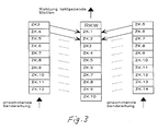
- Fig. 3 shows the summary of the data according to the invention.
- a time-channel-synchronous summary of the data i.e. a summary of the frames in the subnetworks in the time channel grid, in each case made at a branch (network node) and the combined data stream in a new frame, which is specified by a bus station at the network node, transmitted to the central clocking bus station, which in turn transmits this frame in all to the central clocking bus station BST feeds connected subnets.
- FIG. 4 shows an example of a network topology of a time division multiplex transmission system in which the invention can be used.
- the transmission system is advantageously equalized built bus stations formed, which can be operated by appropriate setting or control as a clocking station BST, as a branch or network node or as a subscriber terminal TE.
- a subnetwork with one or more participants can also be connected to each of these stations.
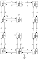
- FIG. 5 shows a block diagram for such a bus station.
- a branch network node
- buses each consisting of transmit and receive line SL or SE
- the bus leading to another network node or to the clocking bus station BST there are correspondingly many interface circuits, in the example IF1, IF2, IF3, are provided, each of which consists of a delay compensation unit LZS, a transmission unit SE and an output stage suitable for the transmission medium, here denoted optics or radio.
- the outputs of all runtime compensation units LZS can be connected via a switching matrix KF to the transmitter units SE of their own interface circuits and to the transmitter units SE of the other interface circuits.
- the switching matrix KF is controlled via a frame generator RG.
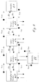
- the runtime compensation units LZS and the transmission units SE are controlled via the bus control BSE. Details of such a bus station are shown in FIG. 6.
- each time channel is only temporarily stored in a runtime compensation unit LZS by the duration of a few time channels, in the exemplary embodiment by a maximum of two time channels, corresponding to 3.906 ⁇ s. Since the frame is on the transmission path, ie in the direction of the clocking bus station BST, in particular if there is no fixed reference to the frame on the reception line EL, the frames on the transmission lines SL of a network node can be any Accept time shifts. As a result, time channels with different numbers are linked in a network node (FIG. 3).
- the frame identification words RKW of the incoming transmission lines are filtered out in the network node.
- the new time channel ZK1 is formed from time channel 3 and time channel 5 of two transmission lines from different subnets.
- the new time channel 2 consists of the linking of time channel 4 and time channel 6.
- a reception buffer EP with a series-parallel conversion unit SP on the input and output sides is present in each delay compensation unit LZS.
- a frame clock derivation and a preparation stage for the time channel clock, which controls the series parallel conversion units SP, and a write / read control for the receive buffer EP are provided.
- the frame identifier words RKW of the incoming data streams are not linked to the outgoing data stream in the direction of the clocking bus station BST. They are therefore not stored in the receive buffer EP and are also not read out of the receive buffer EP at the time of the frame identification word RKW.
- the receive buffer EP In order to obtain a defined state between the incoming and outgoing frame, the receive buffer EP must be initialized.
- the first writing process starts after reinitialization with time channel 1. As soon as this time channel has been completely read in, the reading is released. 7 shows the initialization with a 9-bit receive buffer EP in the runtime compensation unit.
- the individual time channels are separated in parts 1 and 2. As can be derived from FIG. 7, a runtime change ⁇ 9 bits can be compensated for. If the running time increases in the direction of the clocking bus station BST, this can be compensated for until the buffer overflow.
- the Receive buffer EP should be able to accommodate at least three time channels.
- the logical OR operation of the data from the interface and runtime compensation unit LZS takes place on the send route.
- the external clock connection sends the data, which are sent unbuffered and unchanged to the other connections.
- the frame generator RG In the station's own operation, the frame generator RG must transmit the transmission data to the reception path.
- the frame generator RG generates the frame code word RKW and the system clock in own operation. In its own operation, it transfers the data from the send to the receive path.
- the transmitter unit SE forms the counterpart to the runtime compensation unit LZS and is connected upstream of the actual bus interfaces optics, radio or bundle. It enables time channel contents to be overwritten, e.g. Service channel, which is required for network management.
- the data are forwarded to the transmitters in the send direction without any significant delay; symbolized by the switching device DSE.
- the network management and the determination of which of the bus stations is operated as the clock bus station BST is carried out via a service channel which is in opposition to the frame code word RKW (runtime minimization).
- This service channel is rewritten in each network node with the station address and the address of the clocking station (multiplexing of the service channel content). If a new station connects to the network, it evaluates the content of the service channel and adjusts itself accordingly. During the setting phase, it sends out an initialization identifier itself to all other connections in order to indicate the transition phase to other bus stations.
- FIG. 8 shows the system run times for the time channel-synchronous summary of the data for the same network configuration as in FIG. 2.
- a throughput time of 4 ⁇ s (approx. 2 time channels) is assumed for each network node in the transmission path.
- the network nodes send the data out again in the receive path without any change, so that there are only delays in the order of magnitude of gate delays (nanosecond range).
- gate delays nanosecond range.
- a frame with inserted data is sent out from the terminal E1.
- This data is available on the receive line for terminal E1.
- the system runtime depends on the position of the bus station clocking to the respective bus station. Therefore, the system runtime for terminal E2 is only 8 ⁇ s.
- the delays in the system according to FIG. 2 show the savings in the system runtime: System runtime with time channel synchronization: 16 ⁇ s, System runtime with frame synchronization: 1375 ⁇ s.
- the data on the transmit and receive lines can be found in different time channels.
- Receive time channel send time channel + offset .
- Receive time channel send time channel + offset - number of useful channels .
- the useful channels are formed from the number of time channels minus the number of reserved channels (for example the time channel reserved for the frame identifier).
- the 256 time channels of the existing system form 255 user channels.
- the service channel which is in opposition to the frame code RKW, does not have to be taken into account.
- digitally processed voice signals, image signals, control signals, telecontrol signals, computer data, etc. can be transmitted as data.
Landscapes
- Engineering & Computer Science (AREA)
- Computer Hardware Design (AREA)
- Computer Networks & Wireless Communication (AREA)
- Signal Processing (AREA)
- Small-Scale Networks (AREA)
- Time-Division Multiplex Systems (AREA)
Abstract
Bei Zeitmultiplex-Übertragungssystemen für Daten, die in Zeitkanälen eines Rahmens untergebracht sind, ist es bekannt, in den Netzknoten die Datenströme jeweils so zu verzögern, daß sie rahmensynchron zusammengefaßt werden können.
Eine solche rahmensynchrone Zusammenfassung der Datenströme hat den Nachteil, daß die Systemlaufzeiten sehr hoch werden und die Verfügbarkeit sinkt.
Durch eine zeitkanalsynchrone Zusammenfassung der Datenströme können die Systemlaufzeiten vermindert werden. In den Netzknoten sind dazu Laufzeitausgleichseinheiten (LZS) vorgesehen, die die empfangenen Datenströme höchstens um die Dauer von wenigen Zeitkanälen verzögern.
Such a frame-synchronized combination of the data streams has the disadvantage that the system runtimes become very long and the availability decreases.
The system runtimes can be reduced by synchronizing the data streams in a time-channel manner. For this purpose, runtime compensation units (LZS) are provided in the network nodes, which delay the received data streams by a maximum of a few time channels.
Description
Die Erfindung geht aus von einem Übertragungssystem gemäß dem Oberbegriff des Patentanspruches 1.The invention is based on a transmission system according to the preamble of
Aus NTG Fachberichte, Band 80, März 1982, Seiten 157 bis 164 ist ein digitales Zeitmultiplex-Übertragungssystem bekannt, welches als linien- wie auch als sternförmiges synchrones Verzweigungsnetz aufgebaut werden kann. An eine zentrale Busstation werden dezentrale Busstationen beispielsweise über jeweils ein Schleifennetz angeschlossen. An die dezentralen Busstationen können jeweils mehrere Teilnehmer angeschlossen werden. Jeder Teilnehmer kann in diesem DIKOS-System gleichberechtigt einen Verbindungswunsch absetzen. Die Teilnehmer in jedem Schleifennetz können in Zeitkanälen eines Rahmens Daten empfangen und absenden. Der die dezentralen Busstationen eines Teilnetzes verbindende Bus besteht aus einer Sende- und einer Empfangsleitung.A digital time-division multiplex transmission system is known from NTG technical reports, volume 80, March 1982, pages 157 to 164, which can be constructed as a line-like as well as a star-shaped synchronous branching network. Decentralized bus stations are connected to a central bus station, for example via a loop network. Several participants can be connected to the decentralized bus stations. In this DIKOS system, every participant can send a connection request with equal rights. The participants in each loop network can receive and send data in time channels of a frame. The bus connecting the decentralized bus stations of a subnetwork consists of a send and a receive line.
Die von den Busstationen in eine Sendeleitung eingespeisten Informationen werden an einer Datenumleitstelle in die Empfangsleitung der jeweiligen Teilnetze umgeleitet, aus der die Busstationen die an sie gerichteten Daten entnehmen. Die Übertragung erfolgt im Zeitmultiplex, so daß dieses System eine Taktzentrale und einen Rahmensynchronisiergenerator erfordert, die zweckmäßigerweise in der zentralen Busstation untergebracht sind. Jeder Sendeleitung ist eine Laufzeitausgleichseinheit in Form eines Laufzeitspeichers Zugeordnet, der die Laufzeitunterschiede zwischen dem Rahmen auf der Sendeleitung und dem Rahmen vom Rahmensynchronisiergenerator anpaßt. Jede Teilnehmerstation empfängt die Summe aller im Netz vorhandenen Daten, wertet jedoch nur diejenigen aus, die an sie adressiert sind. Die von einer Busstation auszusendenden Daten werden bei DIKOS (s. auch NTZ, Band 34, 1981, Heft 10, Seite 658 bis 663) stets im gleichen Seitkanal auf der Sendeleitung eingespeist und damit auf dem gleichen Seitkanal (Zeitschlitz) wiedergefunden. Um Doppelbelegungen eines Zeitkanals zu vermeiden, sucht zu Beginn einer Verbindung der initiierende Teilnehmer auf der Empfangsleitung einen freien Zeitkanal und sendet, wenn dieser gefunden ist, im selben Zeitkanal der Sendeleitung einen Ruf an einen gewünschten anderen Teilnehmer. Die Summe aller übertragenen Daten wird in der gleichen Reihenfolge auf der Empfangsleitung zu den Teilnehmern übertragen.The information fed into a transmission line by the bus stations is redirected at a data redirection point into the reception line of the respective subnetworks, from which the bus stations take the data directed to them. The transmission takes place in time division multiplex, so that this system requires a clock center and a frame synchronization generator, which are expediently housed in the central bus station. Every transmission line is one Runtime compensation unit in the form of a runtime memory assigned, which adapts the runtime differences between the frame on the transmission line and the frame of the frame synchronization generator. Each subscriber station receives the sum of all data available in the network, but only evaluates those that are addressed to it. At DIKOS (see also NTZ, Volume 34, 1981,
Bei Netzverzweigungen werden die Sendedatenströme rahmensynchron zusammengefaßt und zur zentralen Busstation übertragen, welche diese zusammengefaßten Datenströme wiederum in alle Teilnetze einspeist. Damit sind die im Sendeweg eingeschleusten Daten im Empfangsweg in demselben Zeitkanal zu empfangen.In the case of network branches, the transmitted data streams are combined in a frame-synchronized manner and transmitted to the central bus station, which in turn feeds these combined data streams into all subnetworks. This means that the data introduced into the transmission path can be received in the reception path in the same time channel.
Aufgabe vorliegender Erfindung ist es, gewisse Nachteile dieses Zeitmultiplex-Übertragungssystems zu überwinden. Insbesondere sollen die Systemlaufzeiten verkürzt werden. Diese Aufgabe wird durch die Maßnahmen des Anspruchs 1 gelöst. Die Unteransprüche zeigen vorteilhafte Ausgestaltungen auf.The object of the present invention is to overcome certain disadvantages of this time-division multiplex transmission system. In particular, the system runtimes should be shortened. This object is achieved by the measures of
Der Nachteil des aus vorgenannter Veröffentlichung bekannten Zeitmultiplex-Übertragungssystems ist insbesondere darin zu sehen, daß es in den Verzweigungen (Netzknoten) zu Laufzeiten von bis zu einem Rahmen kommt. Die Anzahl der Verzweigungen (Netzknoten) in der direkten Verbindung zur taktgebenden Station, multipliziert mit der Zeitdauer eines Rahmens, ergibt die Laufzeit eines Datums nach Aussenden bis zum Empfang im Empfangsrahmen. Diese Systemlaufzeit verlängert die Verbindungsaufbauzeiten von Sprach- und Datenverbindungen erheblich, zudem eventuell auftretende Kollisionen unter zusätzlichem Zeitaufwand aufzulösen sind. Hauptsächlich bei breitbandigen Datenübertragungen kommt es zu Wartezeiten oder Datenverlust bei den Endgeräten.The disadvantage of the time-division multiplex transmission system known from the aforementioned publication can be seen in particular in the fact that the branches (network nodes) have runtimes of up to one frame. The number of branches (Network node) in the direct connection to the clocking station, multiplied by the duration of a frame, gives the duration of a date after transmission until reception in the reception frame. This system runtime significantly increases the connection setup times for voice and data connections, and any collisions that may occur can be resolved with additional time. Mainly with broadband data transfers there are waiting times or data loss at the end devices.
Durch die zeitkanalsynchrone Zusammenfassung der Datenströme in den Netzknoten wird die Verweildauer der einzelnen Zeitkanäle in der Laufzeitausgleichseinheit erheblich reduziert und damit die Systemlaufzeit insgesamt verkürzt. Da Kollisionen erst nach Ablauf der Systemlaufzeit erkannt werden, ist beim Zeitmultiplex-Übertragungssystem nach der Erfindung ein neuer Belegungsversuch bereits nach kurzer Zeit möglich. Jeder Netzteilnehmer erhält durch die kurze Systemlaufzeit eine längere Verarbeitungszeit (Verarbeitungszeit = Rahmendauer - Systemlaufzeit) bis zum nächsten Zugriff auf den/die zugeordneten Zeitkanal/Zeitkanäle.The time-channel-synchronized combination of the data streams in the network nodes considerably reduces the length of time that the individual time channels spend in the runtime compensation unit and thus shortens the overall system runtime. Since collisions are only recognized after the system runtime has elapsed, a new occupancy attempt is possible after a short time in the time-division multiplex transmission system according to the invention. The short system runtime gives each network participant a longer processing time (processing time = frame duration - system runtime) until the next access to the assigned time channel (s).
Anhand der Zeichnungen werden nun Ausführungsbeispiele der Erfindung im Vergleich zu einem bisherigen Zeitmultiplex-Übertragungssystem erläutert. Es zeigen beispielhaft
- Fig. 1 den Aufbau eines Zeitmultiplexrahmens,
- Fig. 2 ermittelte Laufzeiten für ein bisheriges Zeitmultiplex-Übertragungssystem,
- Fig. 3 die Zusammenfassung der Daten aus Teilnetzen bei einer Verzweigung,
- Fig. 4 ein Beispiel für eine Netztopologie,
- Fig. 5 ein Blockschaltbild einer Busstation,
- Fig. 6 Einzelheiten einer Busstation,
- Fig. 7 die Initialisierung des Empfangspuffers einer Busstation,
- Fig. 8 die Systemlaufzeiten für ein Zeitmultiplex-Übertragungssystem nach der Erfindung,
- Fig. 9 den Zeitversatz der Rahmen für 6 Busstationen.
- 1 shows the structure of a time-division multiplex frame,
- 2 determined transit times for a previous time-division multiplex transmission system,
- 3 shows the summary of the data from subnets in the case of a branch,
- 4 shows an example of a network topology,
- 5 is a block diagram of a bus station,
- 6 details of a bus station,
- 7 the initialization of the reception buffer of a bus station,
- 8 shows the system run times for a time-division multiplex transmission system according to the invention,
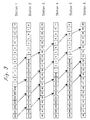
- 9 shows the time offset of the frames for 6 bus stations.
Fig. 1 zeigt den Aufbau eines Zeitmultiplexrahmens, wie er üblicherweise für Zeitmultiplex-Übertragungssysteme verwendet wird. In diesem Beispiel umfaßt der Rahmen insgesamt 256 Zeitkanäle (Zeitschlitze). Der erste Zeitkanal eines Rahmens ist jeweils mit dem Rahmenkennungswort RKW belegt, so daß 255 Nutzkanäle ZK1 bis ZK255 zur Verfügung stehen. Die Gesamtbitrate beträgt 9,216 MBit/s. Auf einen Zeitkanal entfallen 18 Bit und die Bitrate pro Zeitkanal beträgt 32 kBit/s.Fig. 1 shows the structure of a time-division multiplex frame, as is usually used for time-division multiplex transmission systems. In this example, the frame comprises a total of 256 time channels (time slots). The first time channel of a frame is assigned the frame ID word RKW, so that 255 user channels ZK1 to ZK255 are available. The total bit rate is 9.216 Mbit / s. One time channel accounts for 18 bits and the bit rate per time channel is 32 kbit / s.
Um ein Maß für die Systemlaufzeiten zu erhalten, sind in Fig. 2 die Systemlaufzeiten des bekannten DIKOS-Zeitmultiplexsystems mit rahmensynchroner Verarbeitung dargestellt. Im dargestellten Beispiel sind zwischen der taktgebenden Busstation und zwei Endstellen drei Verzweigungen (Netzknoten) vorgesehen. Die Verbindung erfolgt jeweils über einen Datenbus mit Sendeleitung SL und Empfangsleitung EL. Die punktierten Pfeile kennzeichnen jeweils die Zeitpunkte, an denen ein Rahmen vom entsprechenden Punkt (Netzknoten, Endstelle) ausgesendet wird. Der Zeitnullpunkt ist durch das Aussenden eines Rahmens durch die taktgebende Busstation bestimmt.In order to obtain a measure of the system runtimes, the system runtimes of the known DIKOS time division multiplex system with frame-synchronous processing are shown in FIG. 2. In the example shown, three branches (network nodes) are provided between the clocking bus station and two end stations. The connection is made via a data bus with transmission line SL and reception line EL. The dotted arrows indicate the points in time at which a frame is sent out by the corresponding point (network node, terminal). The zero point is through that Sending a frame determined by the clocking bus station.
In der Endstelle (Teilnehmer) E1 werden die Daten zum Zeitpunkt 290 µs in den Rahmen eingeschleust. Der erste Netzknoten K1 sendet den Rahmen zum Zeitpunkt 420 µs aus. Beim zweiten Knoten K2 ist der Rahmen bereits zum Zeitpunkt 365 µs ausgesendet worden, so daß hier auf den nächsten Rahmen bei 865 µs gewartet werden muß. Der letzte Netzknoten K3 sendet die Daten zum Zeitpunkt 1310 µs an die taktgebende Busstation BST. Der nächste Rahmen geht zum Zeitpunkt 1500 µs von der taktgebenden Busstation BST ab und erreicht die Endstelle E1 nach 1665 µs (die Pfeile in Fig. 2 geben jeweils die summierten Laufzeiten an). Die Systemlaufzeit vom Aussenden bis zum Empfang beträgt für die Endstelle E1 demnach insgesamt:

was der Dauer von ca. drei Rahmen entspricht.In the end station (subscriber) E1, the data is introduced into the frame at the point in time 290 microseconds. The first network node K1 sends out the frame at the time 420 μs. At the second node K2, the frame has already been sent out at 365 μs, so that the next frame must be waited for at 865 μs. The last network node K3 sends the data to the clocking bus station BST at the time 1310 microseconds. The next frame leaves the clocking bus station BST at the time 1500 μs and reaches the end point E1 after 1665 μs (the arrows in FIG. 2 each indicate the total transit times). The total system runtime from sending to receiving is therefore:
which corresponds to the duration of approximately three frames.
Fig. 3 zeigt die Zusammenfassung der Daten nach der Erfindung. Anstelle einer rahmensynchronen Zusammenfassung wird eine zeitkanalsynchrone Zusammenfassung der Daten, d.h. eine Zusammenfassung der Rahmen in den Teilnetzen im Zeitkanalraster, jeweils bei einer Verzweigung (Netzknoten) vorgenommen und der zusammengefaßte Datenstrom in einem neuen Rahmen, der von einer Busstation beim Netzknoten vorgegeben wird, zur zentralen taktgebenden Busstation übertragen, welche diesen Rahmen wiederum in alle an die zentrale taktgebende Busstation BST angeschlossenen Teilnetze einspeist.Fig. 3 shows the summary of the data according to the invention. Instead of a frame-synchronous summary, a time-channel-synchronous summary of the data, i.e. a summary of the frames in the subnetworks in the time channel grid, in each case made at a branch (network node) and the combined data stream in a new frame, which is specified by a bus station at the network node, transmitted to the central clocking bus station, which in turn transmits this frame in all to the central clocking bus station BST feeds connected subnets.
Fig. 4 zeigt ein Beispiel für eine Netztopologie eines Zeitmultiplex-Übertragungssystems, bei dem die Erfindung einsetzbar ist. Es sind dort mehrere Netzknoten K1, K2 vorhanden, an denen jeweils eine Busstation BS vorgesehen ist. Vorteilhafterweise wird das Übertragungssystem aus gleich aufgebauten Busstationen gebildet, die durch entsprechende Einstellung oder Steuerung als taktgebende Station BST, als Verzweigung bzw. Netzknoten oder als Teilnehmerendstelle TE betreibbar sind. An jede dieser Stationen kann außerdem ein Teilnetz mit einem oder mehreren Teilnehmern angeschlossen sein.FIG. 4 shows an example of a network topology of a time division multiplex transmission system in which the invention can be used. There are several network nodes K1, K2, each of which has a bus station BS provided. The transmission system is advantageously equalized built bus stations formed, which can be operated by appropriate setting or control as a clocking station BST, as a branch or network node or as a subscriber terminal TE. A subnetwork with one or more participants can also be connected to each of these stations.
Fig. 5 zeigt ein Blockschaltbild für solch eine Busstation. Je nach Anzahl der in einer Verzweigung (Netzknoten) zusammenlaufenden Teilnetze (Busse jeweils bestehend aus Sende- und Empfangsleitung SL bzw. SE) und dem zu einem weiteren Netzknoten oder zur taktgebenden Busstation BST führenden Bus sind entsprechend viele Interface-Schaltungen, im Beispiel IF1, IF2, IF3, vorgesehen, die jeweils aus einer Laufzeitausgleichseinheit LZS, einer Sendeeinheit SE und einer übertragungsmediumgeeigneten Ausgangsstufe, hier mit Optik bzw. Funk bezeichnet, bestehen. Die Ausgänge aller Laufzeitausgleichseinheiten LZS sind über ein Koppelfeld KF mit den Sendeeinheiten SE ihrer eigenen Interface-Schaltungen sowie den Sendeeinheiten SE der anderen Interface-Schaltungen verbindbar. Das Koppelfeld KF wird über einen Rahmengenerator RG gesteuert. Die Steuerung der Laufzeitausgleichseinheiten LZS und der Sendeeinheiten SE erfolgt über die Bussteuerung BSE. Einzelheiten einer solchen Busstation sind in Fig. 6 dargestellt.5 shows a block diagram for such a bus station. Depending on the number of sub-networks converging in a branch (network node) (buses each consisting of transmit and receive line SL or SE) and the bus leading to another network node or to the clocking bus station BST, there are correspondingly many interface circuits, in the example IF1, IF2, IF3, are provided, each of which consists of a delay compensation unit LZS, a transmission unit SE and an output stage suitable for the transmission medium, here denoted optics or radio. The outputs of all runtime compensation units LZS can be connected via a switching matrix KF to the transmitter units SE of their own interface circuits and to the transmitter units SE of the other interface circuits. The switching matrix KF is controlled via a frame generator RG. The runtime compensation units LZS and the transmission units SE are controlled via the bus control BSE. Details of such a bus station are shown in FIG. 6.
Für die erfindungsgemäße zeitkanalsynchrone Zusammenfassung der Daten wird jeder Zeitkanal nur um die Dauer weniger Zeitkanäle, im Ausführungsbeispiel maximal um die Dauer von zwei Zeitkanälen, entsprechend 3,906 µs, in einer Laufzeitausgleichseinheit LZS zwischengespeichert. Da der Rahmen auf dem Sendeweg, d.h. in Richtung taktgebende Busstation BST, insbesondere wenn kein fester Bezug zum Rahmen auf der Empfangsleitung EL vorhanden ist, können die Rahmen auf den Sendeleitungen SL eines Netzknotens beliebige Zeitverschiebungen annehmen. Dadurch werden in einem Netzknoten Zeitkanäle mit verschiedenen Nummern verknüpft (Fig. 3). Für die Verknüpfung der Zeitkanäle über die Laufzeitausgleichseinheiten LZS und das Koppelfeld KF werden im Netzknoten die Rahmenkennungsworte RKW der ankommenden Sendeleitungen ausgefiltert. Richtung taktgebende Busstation BST bildet sich der neue Zeitkanal ZK1 aus Zeitkanal 3 und Zeitkanal 5 zweier Sendeleitungen von unterschiedlichen Teilnetzen. Analog hierzu besteht der neue Zeitkanal 2 aus der Verknüpfung von Zeitkanal 4 und Zeitkanal 6. Für die Verzögerung der Rahmen um maximal zwei Zeitkanäle ist in jeder Laufzeitausgleichseinheit LZS ein Empfangspuffer EP mit ein- und ausgangsseitiger Serienparallelwandlungseinheit SP vorhanden. Außerdem ist eine Rahmentaktableitung und eine Aufbereitungsstufe für den Zeitkanaltakt, der die Serienparallelwandlungseinheiten SP steuert, und eine Schreib/Lesesteuerung für den Empfangspuffer EP vorgesehen. Die Rahmenkennungsworte RKW der ankommenden Datenströme werden nicht mit dem abgehenden Datenstrom in Richtung taktgebende Busstation BST verknüpft. Sie werden daher nicht im Empfangspuffer EP abgelegt und auch nicht zum Zeitpunkt des Rahmenkennungswortes RKW aus dem Empfangspuffer EP ausgelesen. Um einen definierten Zustand zwischen ankommendem und abgehendem Rahmen zu erhalten, muß der Empfangspuffer EP initialisiert werden. Dabei startet der erste Einschreibvorgang nach Neuinitialisierung mit dem Zeitkanal 1. Sobald dieser Zeitkanal komplett eingelesen ist, wird das Auslesen freigegeben. Fig. 7 zeigt die Initialisierung mit einem 9 Bit breiten Empfangspuffer EP in der Laufzeitausgleichseinheit. Die einzelnen Zeitkanäle sind in Teil 1 und 2 getrennt. Wie aus Fig. 7 abzuleiten ist, kann eine Laufzeitänderung < 9 Bit ausgeglichen werden. Erhöht sich die Laufzeit in Richtung taktgebender Busstation BST, so kann diese bis zum Pufferüberlauf ausgeglichen werden. Der Empfangspuffer EP sollte mindestens drei Zeitkanäle aufnehmen können.For the time channel-synchronous summary of the data, each time channel is only temporarily stored in a runtime compensation unit LZS by the duration of a few time channels, in the exemplary embodiment by a maximum of two time channels, corresponding to 3.906 μs. Since the frame is on the transmission path, ie in the direction of the clocking bus station BST, in particular if there is no fixed reference to the frame on the reception line EL, the frames on the transmission lines SL of a network node can be any Accept time shifts. As a result, time channels with different numbers are linked in a network node (FIG. 3). In order to link the time channels via the runtime compensation units LZS and the switching matrix KF, the frame identification words RKW of the incoming transmission lines are filtered out in the network node. In the direction of the clocking bus station BST, the new time channel ZK1 is formed from
Im Zeitraum zwischen Rahmenkennungswort RKW des ankommenden Datenstromes und dem Rahmenkennungswort RKW des abgehenden Datenstroms besteht eine Verzögerung von einem Zeitkanal. Nach dem abgehenden Rahmenkennungswort RKW wird der ankommende Datenstrom für die Dauer von zwei Zeitkanälen zwischengespeichert.There is a delay of one time channel in the period between frame identifier RKW of the incoming data stream and frame identifier RKW of the outgoing data stream. After the outgoing frame identifier word RKW, the incoming data stream is temporarily stored for the duration of two time channels.
Über das Koppelfeld KF erfolgt die Einstellung einer Busstation im Netz. Neben der Zusammenfassung der Datenströme durch verdrahtete wired-or Verknüpfungen (logische ODER Funktion) aller Datenströme angeschlossener Teilnetze, hat dieses Koppelfeld KF noch folgende weitere Aufgaben:
- Einstellung von Fremdtakt- oder Eigenbetrieb,
- Transparentes Durchschalten von Sende- und Empfangsweg zur Realisierung einer Busstation mit minimaler Laufzeit (DBS Funktion).
- Setting external clock or own operation,
- Transparent switching of the send and receive path to implement a bus station with a minimum runtime (DBS function).
Sendeweg:
- DS
- - Sendedaten (Daten Richtung taktgebende Station),
- TS
- - Sendetakt (synchroner Takt von Fremdtaktanschluß oder vom Rahmengenerator RF),
- SYNS
- - Synchronisiersignal (z.B. Zeitkanaltakt mit Taktpause während eines Rahmenkennungswortes RKW).
- DS
- - transmission data (data towards clocking station),
- TS
- - transmit clock (synchronous clock from external clock connection or from the frame generator RF),
- SYNS
- - Synchronization signal (eg time channel clock with clock pause during a frame code word RKW).
Empfangsweg:
- DE
- - Empfangsdaten (Daten von taktgebender Station),
- TE
- - Empfangstakt (synchroner Takt von Fremdtaktanschluß oder vom Rahmengenerator RG),
- SYNE
- - Synchronisiersignal (z.B. Zeitkanaltakt mit Taktpause während eines Rahmenkennungswortes RKW).
- DE
- - receive data (data from clocking station),
- TE
- - receive clock (synchronous clock from external clock connection or from the frame generator RG),
- SYNE
- - Synchronization signal (eg time channel clock with clock pause during a frame code word RKW).
Auf dem Sendeweg findet die logische ODER-Verknüpfung der Daten von Interface und Laufzeitausgleichseinheit LZS (außer Fremdtaktanschluß) statt. Im Empfangsweg sendet der Fremdtaktanschluß die Daten, welche ungepuffert und unverändert an den anderen Anschlüssen ausgesendet werden. Im Eigenbetrieb der Station muß der Rahmengenerator RG die Sendedaten auf den Empfangsweg übertragen.The logical OR operation of the data from the interface and runtime compensation unit LZS (except for external clock connection) takes place on the send route. In the receive path, the external clock connection sends the data, which are sent unbuffered and unchanged to the other connections. In the station's own operation, the frame generator RG must transmit the transmission data to the reception path.
Der Rahmengenerator RG erzeugt das Rahmenkennungswort RKW und den Systemtakt im Eigenbetrieb. Er überträgt im Eigenbetrieb die Daten vom Sende- in den Empfangsweg. Die Sendeeinheit SE bildet das Gegenstück zur Laufzeitausgleichseinheit LZS und ist den eigentlichen Busschnittstellen Optik, Funk oder Bündel vorgeschaltet. Sie ermöglicht das Überschreiben von Zeitkanalinhalten, z.B. Dienstkanal, was für das Netzmanagement erforderlich ist. Die Daten werden in Senderichtung ohne nennenswerte Verzögerung an die Sender weitergeleitet; symbolisiert durch die Durchschalteinrichtung DSE.The frame generator RG generates the frame code word RKW and the system clock in own operation. In its own operation, it transfers the data from the send to the receive path. The transmitter unit SE forms the counterpart to the runtime compensation unit LZS and is connected upstream of the actual bus interfaces optics, radio or bundle. It enables time channel contents to be overwritten, e.g. Service channel, which is required for network management. The data are forwarded to the transmitters in the send direction without any significant delay; symbolized by the switching device DSE.
Das Netzmanagement und die Ermittlung, welche der Busstationen als taktgebende Busstation BST betrieben wird, erfolgt über einen Dienstkanal, welcher in Opposition zum Rahmenkennungswort RKW steht (Laufzeitminimierung). Dieser Dienstkanal wird in jedem Netzknoten mit der Stationsadresse und der Adresse der taktgebenden Station neu beschrieben (Multiplexen des Dienstkanalinhalts). Schließt sich eine neue Station an das Netz an, so wertet sie den Inhalt des Dienstkanals aus und stellt sich entsprechend ein. Während der Einstellphase sendet sie selbst eine Initialisierungskennung an allen anderen Anschlüssen aus, um andere Busstationen die Übergangsphase anzuzeigen.The network management and the determination of which of the bus stations is operated as the clock bus station BST is carried out via a service channel which is in opposition to the frame code word RKW (runtime minimization). This service channel is rewritten in each network node with the station address and the address of the clocking station (multiplexing of the service channel content). If a new station connects to the network, it evaluates the content of the service channel and adjusts itself accordingly. During the setting phase, it sends out an initialization identifier itself to all other connections in order to indicate the transition phase to other bus stations.
Läuft in jedem Netzknoten der Rahmengenerator RG nur taktsynchron, entstehen beim Umschalten auf Fremdtakt keine Synchronismusausfälle mehr. Eine Netzumkonfiguration muß den anderen Busstationen daher über eine Dienstkanalkennung mitgeteilt werden.If the frame generator RG in each network node only runs in isochronous mode, none occur when switching to an external clock Failure to synchronize more. A network reconfiguration must therefore be communicated to the other bus stations via a service channel identifier.
Folgende Möglichkeiten bietet der gemultiplexte Dienstkanal:
- sanftes Herunterfahren des Netzes (z.B. bei Stellungswechsel),
- definiertes Schalten und Lösen von Netzverbindungen,
- automatische Netzkonfiguration unter Berücksichtigung von Laufzeiten,
- Übersicht über geschaltete und logisch getrennte Verbindungen mit entsprechenden Partneradressen (graph. Netztopologie),
- Anschaltung weiterer Busstationen ohne Netzstörungen.
- gentle shutdown of the network (e.g. when changing positions),
- defined switching and disconnection of network connections,
- automatic network configuration taking into account runtimes,
- Overview of switched and logically separated connections with corresponding partner addresses (graphical network topology),
- Connection of additional bus stations without network disturbances.
Letztere Merkmale lassen sich insbesondere über einen optischen Anschluß realisieren, welcher mit ca. drei verschiedenen Inhalten für den Dienstkanal beschrieben werden kann und diese im Wechsel für jeden Rahmen aussendet.The latter features can be realized in particular via an optical connection which can be described with approximately three different contents for the service channel and which is transmitted alternately for each frame.
In Fig. 8 sind für die gleiche Netzkonfiguration wie in Fig. 2 die Systemlaufzeiten für die erfindungsgemäße zeitkanalsynchrone Zusammenfassung der Daten dargestellt.
Im Sendeweg wird für jeden Netzknoten eine Durchlaufzeit von 4 µs (ca. 2 Zeitkanäle) angenommen. Die Netzknoten senden im Empfangsweg die Daten ohne Veränderung wieder aus, so daß es hier nur zu Verzögerungen in Größenordnung von Gatterlaufzeiten (Nanosekundenbereich) kommt. Zum Zeitpunkt O µs wird ein Rahmen mit eingeschleusten Daten von der Endstelle E1 ausgesendet. Diese Daten stehen zum Zeitpunkt 16 µs auf der Empfangsleitung für die Endstelle E1 zur Verfügung. Die Systemlaufzeit ist abhängig von der Position der zur jeweiligen Busstation taktgebenden Busstation. Deshalb beträgt für die Endstelle E2 die Systemlaufzeit nur 8 µs. Im Vergleich zu den Verzögerungen des Systems gemäß Fig. 2 werden die Einsparungen in der Systemlaufzeit deutlich:
Systemlaufzeit bei Zeitkanalsynchronisation: 16 µs,
Systemlaufzeit bei Rahmensynchronisation: 1375 µs.FIG. 8 shows the system run times for the time channel-synchronous summary of the data for the same network configuration as in FIG. 2.
A throughput time of 4 µs (approx. 2 time channels) is assumed for each network node in the transmission path. The network nodes send the data out again in the receive path without any change, so that there are only delays in the order of magnitude of gate delays (nanosecond range). At the point in time O µs, a frame with inserted data is sent out from the terminal E1. At the time of 16 microseconds, this data is available on the receive line for terminal E1. The system runtime depends on the position of the bus station clocking to the respective bus station. Therefore, the system runtime for terminal E2 is only 8 µs. Compared The delays in the system according to FIG. 2 show the savings in the system runtime:
System runtime with time channel synchronization: 16 µs,
System runtime with frame synchronization: 1375 µs.
Dies bedeutet eine Verringerung der Systemlaufzeit um 1359 µs, entsprechend 98,8 %.This means a 1359 µs reduction in system runtime, corresponding to 98.8%.
Folgende Vorteile stellen sich durch die verringerte Systemlaufzeit ein:
- Kollisionen können erst nach Ablauf der Systemlaufzeit erkannt werden, d.h. bei Zeitkanalsynchronisation ist der nächste Belegungsversuch bereits nach kurzer Zeit möglich.
- Jeder Netzteilnehmer erhält durch die kurze Systemlaufzeit Verarbeitungszeit bis zum nächsten Zugriff auf den Zeitkanal, die sich folgendermaßen ergibt:

Für die Endstelle E1 gilt beispielsweise:

The following advantages result from the reduced system runtime:
- Collisions can only be recognized after the system runtime has expired, ie with time channel synchronization, the next assignment attempt is possible after a short time.
- Due to the short system runtime, each network participant receives processing time until the next access to the time channel, which results as follows:
For the terminal E1, for example:
Zu beachten ist, daß beim Verfahren nach der Erfindung die Daten auf den Sende- und Empfangsleitungen in unterschiedlichen Zeitkanälen zu finden sind.It should be noted that in the method according to the invention, the data on the transmit and receive lines can be found in different time channels.
Nach einer Ausgestaltungsmöglichkeit der Erfindung werden zur richtigen Zuordnung der Zeitkanäle für Sende- und Empfangsweg die Laufzeiten aus der Netztopologie ermittelt und es erfolgt eine fest vereinbarte Zuordnung zwischen den Rahmen bezüglich Sende- und Empfangsweg, d.h. der Zeitversatz (Offset) wird fest vorgegeben und ist den jeweiligen Busstationen bekannt. Bei einer anderen Ausgestaltungsmöglichkeit nach der Erfindung ermittelt jede Busstation den Zeitversatz (Offset) der Zeitkanäle zwischen Sende- und Empfangsleitung selbst. Für die Ermittlung des Offset muß jede Busstation eine Kontrollbelegung durchführen. Dazu sendet sie in einen vorbestimmten Zeitkanal ihre Kennung aus und überwacht die Zeitkanäle auf der Empfangsleitung. Nach Empfang der Kennung auf der Empfangsleitung kann der Offset zwischen Sende- und Empfangsleitung bestimmt werden. Dabei ist zu beachten, daß jeder Netzknoten das Rahmenkennwort RKW neu einfügt. Fig. 9 zeigt für 6 Stationen den jeweiligen Zeitversatz und die Verschiebung der Rahmen (erkenntlich am Rahmenkennungswort RKW). Die Rahmengeneratoren RG der Busstationen sind also nicht rahmensynchronisiert. Die Offset-Ermittlung muß über eine Fallunterscheidung durchgeführt werden:
- 1.

- 2.

- 1.
- 2nd
Sobald der Offset bestimmt ist, kann jedem Sendezeitkanal ein Empfangszeitkanal zugeordnet werden:

As soon as the offset is determined, a reception time channel can be assigned to each transmission time channel:
Erhält der Empfangszeitkanal einen Wert größer als die Anzahl der Nutzkanäle, so muß folgende Korrektur angewendet werden:

If the reception time channel receives a value greater than the number of user channels, the following correction must be applied:
Die Nutzkanäle bilden sich aus der Anzahl Zeitkanäle abzüglich der Zahl der reservierten Kanäle (beispielsweise dem für das Rahmenkennungswort reservierten Zeitkanal). Die 256 Zeitkanäle des bestehenden Systems bilden 255 Nutzkanäle. Der Dienstkanal, der in Opposition zum Rahmenkennungswort RKW steht, muß nicht berücksichtigt werden.The useful channels are formed from the number of time channels minus the number of reserved channels (for example the time channel reserved for the frame identifier). The 256 time channels of the existing
Der Vorteil dieser Methode:
- Keine Rahmensynchronisation der Rahmengeneratoren bei Fremdtakt erforderlich,
- Fremdtaktanschluß ohne Synchronismusverlust für das nachfolgende Netz.
- No frame synchronization of the frame generators required with external clock,
- External clock connection without loss of synchronism for the subsequent network.
Zu beachten ist bei dieser Methode folgendes:
- Eine Netzänderung muß jeder Busstation zuerst bekanntgemacht werden,
- Nach jeder Netzänderung ist eine Kontrollbelegung bei allen Busstationen erforderlich.
- A network change must first be announced to every bus station,
- After every network change, a control assignment is required for all bus stations.
Als Daten können beispielsweise digital aufbereitete Sprachsignale, Bildsignale, Steuersignale, Fernwirksignale, Rechnerdaten usw. übertragen werden.For example, digitally processed voice signals, image signals, control signals, telecontrol signals, computer data, etc. can be transmitted as data.
Claims (8)
dadurch gekennzeichnet,
daß die Laufzeitausgleichseinheit (LZS) so ausgebildet oder so steuerbar ist, daß die Daten für die Verknüpfung in Senderichtung so verzögert werden, daß sie zeitkanalsynchron zusammenfassbar sind, wobei die Verzögerung pro Verzweigung höchstens der Dauer weniger Zeitkanäle entspricht.Time-division multiplex transmission system for data, consisting of several subnetworks, each with a data bus (EL, SL) via which the subscriber (TE) can receive and send data in time channels of a frame, at least one branch (K1, K2, K3, ...) is provided, which is assigned at least one runtime compensation unit (LZS) for delaying data of at least one data bus (EL, SL) and means (KF) for linking the data streams of at least two subnetworks are provided for feeding the linked data streams into the latter or further subnetworks,
characterized,
that the runtime compensation unit (LZS) is designed or controllable in such a way that the data for the link in the transmission direction are delayed in such a way that they can be summarized in a time-channel-synchronized manner, the delay per branch corresponding at most to the duration of a few time channels.
Applications Claiming Priority (2)
| Application Number | Priority Date | Filing Date | Title |
|---|---|---|---|
| DE19924243441 DE4243441C1 (en) | 1992-12-22 | 1992-12-22 | Time division multiplex data transmission system - has data streams for 2 or more partial networks combined with controlled delay providing time slot channel synchronisation. |
| DE4243441 | 1992-12-22 |
Publications (2)
| Publication Number | Publication Date |
|---|---|
| EP0603635A2 true EP0603635A2 (en) | 1994-06-29 |
| EP0603635A3 EP0603635A3 (en) | 1995-01-04 |
Family
ID=6476083
Family Applications (1)
| Application Number | Title | Priority Date | Filing Date |
|---|---|---|---|
| EP93119729A Withdrawn EP0603635A3 (en) | 1992-12-22 | 1993-12-08 | Time multiplex transmission system with propagation time compensation. |
Country Status (2)
| Country | Link |
|---|---|
| EP (1) | EP0603635A3 (en) |
| DE (1) | DE4243441C1 (en) |
Families Citing this family (1)
| Publication number | Priority date | Publication date | Assignee | Title |
|---|---|---|---|---|
| DE19523489A1 (en) * | 1995-06-28 | 1997-01-02 | Sel Alcatel Ag | Method and circuit arrangement for the synchronization of pulse frames in multicellular telecommunications systems |
Family Cites Families (3)
| Publication number | Priority date | Publication date | Assignee | Title |
|---|---|---|---|---|
| DE2208159B2 (en) * | 1972-02-22 | 1976-06-24 | Licentia Patent-Verwaltungs-Gmbh, 6000 Frankfurt | MESSAGE TRANSMISSION SYSTEM FOR A MULTIPLE RICHED NETWORK |
| DE2917675A1 (en) * | 1979-04-27 | 1980-11-06 | Hertz Inst Heinrich | DIGITAL TIME MULTIPLEX MESSAGE SYSTEM |
| FR2526250B1 (en) * | 1982-04-30 | 1988-05-13 | Labo Electronique Physique | METHOD FOR AUTOMATIC TIME SETTING OF STATIONS IN A MULTIPLEX TRANSMISSION AND DATA PROCESSING SYSTEM |
-
1992
- 1992-12-22 DE DE19924243441 patent/DE4243441C1/en not_active Expired - Fee Related
-
1993
- 1993-12-08 EP EP93119729A patent/EP0603635A3/en not_active Withdrawn
Also Published As
| Publication number | Publication date |
|---|---|
| DE4243441C1 (en) | 1994-04-14 |
| EP0603635A3 (en) | 1995-01-04 |
Similar Documents
| Publication | Publication Date | Title |
|---|---|---|
| AT410875B (en) | METHOD AND SYSTEM FOR TRANSMITTING DATA | |
| EP0683619A2 (en) | Method and apparatus for the diversion of a communication cell stream to an alternative path | |
| DE69029513T2 (en) | MULTIPLE ACCESS SYSTEM FOR A TRANSMISSION NETWORK | |
| DE2714368C3 (en) | Circuit arrangement for switching through data words with different bit rate frequencies in multiple connections | |
| DE19906867C1 (en) | Serial data communications method involves each slave filtering data frames provided for it from bus forward line and passing them directly to bus return line after processing | |
| DE3850156T2 (en) | Asynchronous time division multiplex transmission system. | |
| EP1599980B1 (en) | Synchronous multi-cluster network architecture | |
| DE3885867T2 (en) | Device for data packet conversion in a uniform multiplex in a TDMA transmission system. | |
| EP1631013B1 (en) | Main station and auxiliary station in a switched data network and method for transmitting data in such a network | |
| EP0765050A2 (en) | Method for controlling the transmission of digital communication signals via a time division multiplex medium | |
| DE29908608U1 (en) | Network and coupling device for connecting two segments in such a network and network participants | |
| EP0185936B1 (en) | Interface circuit arrangement for connecting data sources with data sinks, and switching systems with such an interface circuit arrangement | |
| DE4243441C1 (en) | Time division multiplex data transmission system - has data streams for 2 or more partial networks combined with controlled delay providing time slot channel synchronisation. | |
| EP2345209B1 (en) | Method and device for transferring data over network nodes of a network | |
| EP0448927A1 (en) | Procedure for the transmission of time discrete information | |
| DE4243442C1 (en) | Time multiplex transmission procedure - combining incoming data streams at each network node with time slot frame synchronisation maintained | |
| DE102005034652B4 (en) | Bus system and method for operating the bus system | |
| EP0343319B1 (en) | Digital-information transmission method for communication-switching systems | |
| DE69209368T2 (en) | Transmission channels with variable data rate for digital networks | |
| DE4233581A1 (en) | Multiplex frame structure for optical digital communication system - includes frame overhead able to determine position and size of traffic bursts with predetermined number of data channels | |
| DE2828602B1 (en) | Method for transmitting data in a synchronous data network | |
| DE2932735C2 (en) | Digital signal time division multiplex telecommunications system | |
| DE4134360C1 (en) | ||
| DE69219537T2 (en) | Method and arrangement for message transmission between devices of a communication system | |
| EP0759682B1 (en) | Digital message switching system |
Legal Events
| Date | Code | Title | Description |
|---|---|---|---|
| PUAI | Public reference made under article 153(3) epc to a published international application that has entered the european phase |
Free format text: ORIGINAL CODE: 0009012 |
|
| AK | Designated contracting states |
Kind code of ref document: A2 Designated state(s): AT BE CH ES FR GB LI NL |
|
| PUAL | Search report despatched |
Free format text: ORIGINAL CODE: 0009013 |
|
| AK | Designated contracting states |
Kind code of ref document: A3 Designated state(s): AT BE CH ES FR GB LI NL |
|
| 17P | Request for examination filed |
Effective date: 19941207 |
|
| RAP1 | Party data changed (applicant data changed or rights of an application transferred) |
Owner name: ROBERT BOSCH GMBH |
|
| STAA | Information on the status of an ep patent application or granted ep patent |
Free format text: STATUS: THE APPLICATION IS DEEMED TO BE WITHDRAWN |
|
| 18D | Application deemed to be withdrawn |
Effective date: 19990701 |