EP0603635A2 - Système de transmission de multiplexage temporel avec compensation de temps de la propagation - Google Patents
Système de transmission de multiplexage temporel avec compensation de temps de la propagation Download PDFInfo
- Publication number
- EP0603635A2 EP0603635A2 EP93119729A EP93119729A EP0603635A2 EP 0603635 A2 EP0603635 A2 EP 0603635A2 EP 93119729 A EP93119729 A EP 93119729A EP 93119729 A EP93119729 A EP 93119729A EP 0603635 A2 EP0603635 A2 EP 0603635A2
- Authority
- EP
- European Patent Office
- Prior art keywords
- time
- data
- transmission
- transmission system
- frame
- Prior art date
- Legal status (The legal status is an assumption and is not a legal conclusion. Google has not performed a legal analysis and makes no representation as to the accuracy of the status listed.)
- Withdrawn
Links
- 230000005540 biological transmission Effects 0.000 title claims abstract description 54
- 239000011159 matrix material Substances 0.000 claims description 7
- 230000003111 delayed effect Effects 0.000 claims 1
- 230000007423 decrease Effects 0.000 abstract 1
- 230000008859 change Effects 0.000 description 4
- 238000000034 method Methods 0.000 description 4
- 230000001934 delay Effects 0.000 description 3
- 230000001360 synchronised effect Effects 0.000 description 3
- 239000008186 active pharmaceutical agent Substances 0.000 description 2
- 230000008901 benefit Effects 0.000 description 2
- 238000006243 chemical reaction Methods 0.000 description 2
- 238000010586 diagram Methods 0.000 description 2
- 230000006870 function Effects 0.000 description 2
- 238000009795 derivation Methods 0.000 description 1
- 230000000977 initiatory effect Effects 0.000 description 1
- 230000003287 optical effect Effects 0.000 description 1
- 230000008569 process Effects 0.000 description 1
- 230000009467 reduction Effects 0.000 description 1
- 230000007704 transition Effects 0.000 description 1
- 238000011144 upstream manufacturing Methods 0.000 description 1
Images


Classifications
-
- H—ELECTRICITY
- H04—ELECTRIC COMMUNICATION TECHNIQUE
- H04J—MULTIPLEX COMMUNICATION
- H04J3/00—Time-division multiplex systems
- H04J3/02—Details
- H04J3/06—Synchronising arrangements
- H04J3/062—Synchronisation of signals having the same nominal but fluctuating bit rates, e.g. using buffers
- H04J3/0626—Synchronisation of signals having the same nominal but fluctuating bit rates, e.g. using buffers plesiochronous multiplexing systems, e.g. plesiochronous digital hierarchy [PDH], jitter attenuators
Definitions
- the invention is based on a transmission system according to the preamble of patent claim 1.
- a digital time-division multiplex transmission system is known from NTG technical reports, volume 80, March 1982, pages 157 to 164, which can be constructed as a line-like as well as a star-shaped synchronous branching network.
- Decentralized bus stations are connected to a central bus station, for example via a loop network.
- Several participants can be connected to the decentralized bus stations.
- every participant can send a connection request with equal rights.
- the participants in each loop network can receive and send data in time channels of a frame.
- the bus connecting the decentralized bus stations of a subnetwork consists of a send and a receive line.
- the information fed into a transmission line by the bus stations is redirected at a data redirection point into the reception line of the respective subnetworks, from which the bus stations take the data directed to them.
- the transmission takes place in time division multiplex, so that this system requires a clock center and a frame synchronization generator, which are expediently housed in the central bus station.
- Every transmission line is one Runtime compensation unit in the form of a runtime memory assigned, which adapts the runtime differences between the frame on the transmission line and the frame of the frame synchronization generator.
- Each subscriber station receives the sum of all data available in the network, but only evaluates those that are addressed to it.
- the data to be sent out by a bus station is always fed into the same side channel on the transmission line and thus found on the same side channel (time slot).
- the initiating subscriber searches for a free time channel on the reception line at the start of a connection and, if this is found, sends a call to a desired other subscriber in the same time channel of the transmission line. The sum of all transmitted data is transmitted in the same order on the receiving line to the participants.
- the transmitted data streams are combined in a frame-synchronized manner and transmitted to the central bus station, which in turn feeds these combined data streams into all subnetworks. This means that the data introduced into the transmission path can be received in the reception path in the same time channel.
- the object of the present invention is to overcome certain disadvantages of this time-division multiplex transmission system.
- the system runtimes should be shortened.
- This object is achieved by the measures of claim 1.
- the subclaims show advantageous configurations.
- the disadvantage of the time-division multiplex transmission system known from the aforementioned publication can be seen in particular in the fact that the branches (network nodes) have runtimes of up to one frame.
- This system runtime significantly increases the connection setup times for voice and data connections, and any collisions that may occur can be resolved with additional time. Mainly with broadband data transfers there are waiting times or data loss at the end devices.
- the time-channel-synchronized combination of the data streams in the network nodes considerably reduces the length of time that the individual time channels spend in the runtime compensation unit and thus shortens the overall system runtime. Since collisions are only recognized after the system runtime has elapsed, a new occupancy attempt is possible after a short time in the time-division multiplex transmission system according to the invention.
- Fig. 1 shows the structure of a time-division multiplex frame, as is usually used for time-division multiplex transmission systems.
- the frame comprises a total of 256 time channels (time slots).
- the first time channel of a frame is assigned the frame ID word RKW, so that 255 user channels ZK1 to ZK255 are available.
- the total bit rate is 9.216 Mbit / s.
- One time channel accounts for 18 bits and the bit rate per time channel is 32 kbit / s.
- FIG. 2 the system runtimes of the known DIKOS time division multiplex system with frame-synchronous processing are shown in FIG. 2.
- three branches are provided between the clocking bus station and two end stations. The connection is made via a data bus with transmission line SL and reception line EL.
- the dotted arrows indicate the points in time at which a frame is sent out by the corresponding point (network node, terminal). The zero point is through that Sending a frame determined by the clocking bus station.
- the data is introduced into the frame at the point in time 290 microseconds.
- the first network node K1 sends out the frame at the time 420 ⁇ s.
- the frame has already been sent out at 365 ⁇ s, so that the next frame must be waited for at 865 ⁇ s.
- the last network node K3 sends the data to the clocking bus station BST at the time 1310 microseconds.
- the next frame leaves the clocking bus station BST at the time 1500 ⁇ s and reaches the end point E1 after 1665 ⁇ s (the arrows in FIG. 2 each indicate the total transit times).
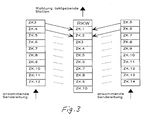
- Fig. 3 shows the summary of the data according to the invention.
- a time-channel-synchronous summary of the data i.e. a summary of the frames in the subnetworks in the time channel grid, in each case made at a branch (network node) and the combined data stream in a new frame, which is specified by a bus station at the network node, transmitted to the central clocking bus station, which in turn transmits this frame in all to the central clocking bus station BST feeds connected subnets.
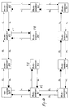
- FIG. 4 shows an example of a network topology of a time division multiplex transmission system in which the invention can be used.
- the transmission system is advantageously equalized built bus stations formed, which can be operated by appropriate setting or control as a clocking station BST, as a branch or network node or as a subscriber terminal TE.
- a subnetwork with one or more participants can also be connected to each of these stations.
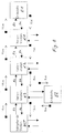
- FIG. 5 shows a block diagram for such a bus station.
- a branch network node
- buses each consisting of transmit and receive line SL or SE
- the bus leading to another network node or to the clocking bus station BST there are correspondingly many interface circuits, in the example IF1, IF2, IF3, are provided, each of which consists of a delay compensation unit LZS, a transmission unit SE and an output stage suitable for the transmission medium, here denoted optics or radio.
- the outputs of all runtime compensation units LZS can be connected via a switching matrix KF to the transmitter units SE of their own interface circuits and to the transmitter units SE of the other interface circuits.
- the switching matrix KF is controlled via a frame generator RG.
- the runtime compensation units LZS and the transmission units SE are controlled via the bus control BSE. Details of such a bus station are shown in FIG. 6.
- each time channel is only temporarily stored in a runtime compensation unit LZS by the duration of a few time channels, in the exemplary embodiment by a maximum of two time channels, corresponding to 3.906 ⁇ s. Since the frame is on the transmission path, ie in the direction of the clocking bus station BST, in particular if there is no fixed reference to the frame on the reception line EL, the frames on the transmission lines SL of a network node can be any Accept time shifts. As a result, time channels with different numbers are linked in a network node (FIG. 3).
- the frame identification words RKW of the incoming transmission lines are filtered out in the network node.
- the new time channel ZK1 is formed from time channel 3 and time channel 5 of two transmission lines from different subnets.
- the new time channel 2 consists of the linking of time channel 4 and time channel 6.
- a reception buffer EP with a series-parallel conversion unit SP on the input and output sides is present in each delay compensation unit LZS.
- a frame clock derivation and a preparation stage for the time channel clock, which controls the series parallel conversion units SP, and a write / read control for the receive buffer EP are provided.
- the frame identifier words RKW of the incoming data streams are not linked to the outgoing data stream in the direction of the clocking bus station BST. They are therefore not stored in the receive buffer EP and are also not read out of the receive buffer EP at the time of the frame identification word RKW.
- the receive buffer EP In order to obtain a defined state between the incoming and outgoing frame, the receive buffer EP must be initialized.
- the first writing process starts after reinitialization with time channel 1. As soon as this time channel has been completely read in, the reading is released. 7 shows the initialization with a 9-bit receive buffer EP in the runtime compensation unit.
- the individual time channels are separated in parts 1 and 2. As can be derived from FIG. 7, a runtime change ⁇ 9 bits can be compensated for. If the running time increases in the direction of the clocking bus station BST, this can be compensated for until the buffer overflow.
- the Receive buffer EP should be able to accommodate at least three time channels.
- the logical OR operation of the data from the interface and runtime compensation unit LZS takes place on the send route.
- the external clock connection sends the data, which are sent unbuffered and unchanged to the other connections.
- the frame generator RG In the station's own operation, the frame generator RG must transmit the transmission data to the reception path.
- the frame generator RG generates the frame code word RKW and the system clock in own operation. In its own operation, it transfers the data from the send to the receive path.
- the transmitter unit SE forms the counterpart to the runtime compensation unit LZS and is connected upstream of the actual bus interfaces optics, radio or bundle. It enables time channel contents to be overwritten, e.g. Service channel, which is required for network management.
- the data are forwarded to the transmitters in the send direction without any significant delay; symbolized by the switching device DSE.
- the network management and the determination of which of the bus stations is operated as the clock bus station BST is carried out via a service channel which is in opposition to the frame code word RKW (runtime minimization).
- This service channel is rewritten in each network node with the station address and the address of the clocking station (multiplexing of the service channel content). If a new station connects to the network, it evaluates the content of the service channel and adjusts itself accordingly. During the setting phase, it sends out an initialization identifier itself to all other connections in order to indicate the transition phase to other bus stations.
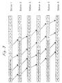
- FIG. 8 shows the system run times for the time channel-synchronous summary of the data for the same network configuration as in FIG. 2.
- a throughput time of 4 ⁇ s (approx. 2 time channels) is assumed for each network node in the transmission path.
- the network nodes send the data out again in the receive path without any change, so that there are only delays in the order of magnitude of gate delays (nanosecond range).
- gate delays nanosecond range.
- a frame with inserted data is sent out from the terminal E1.
- This data is available on the receive line for terminal E1.
- the system runtime depends on the position of the bus station clocking to the respective bus station. Therefore, the system runtime for terminal E2 is only 8 ⁇ s.
- the delays in the system according to FIG. 2 show the savings in the system runtime: System runtime with time channel synchronization: 16 ⁇ s, System runtime with frame synchronization: 1375 ⁇ s.
- the data on the transmit and receive lines can be found in different time channels.
- Receive time channel send time channel + offset .
- Receive time channel send time channel + offset - number of useful channels .
- the useful channels are formed from the number of time channels minus the number of reserved channels (for example the time channel reserved for the frame identifier).
- the 256 time channels of the existing system form 255 user channels.
- the service channel which is in opposition to the frame code RKW, does not have to be taken into account.
- digitally processed voice signals, image signals, control signals, telecontrol signals, computer data, etc. can be transmitted as data.
Landscapes
- Engineering & Computer Science (AREA)
- Computer Hardware Design (AREA)
- Computer Networks & Wireless Communication (AREA)
- Signal Processing (AREA)
- Small-Scale Networks (AREA)
- Time-Division Multiplex Systems (AREA)
Applications Claiming Priority (2)
| Application Number | Priority Date | Filing Date | Title |
|---|---|---|---|
| DE19924243441 DE4243441C1 (de) | 1992-12-22 | 1992-12-22 | Zeitmultiplex-Übertragungssystem |
| DE4243441 | 1992-12-22 |
Publications (2)
| Publication Number | Publication Date |
|---|---|
| EP0603635A2 true EP0603635A2 (fr) | 1994-06-29 |
| EP0603635A3 EP0603635A3 (fr) | 1995-01-04 |
Family
ID=6476083
Family Applications (1)
| Application Number | Title | Priority Date | Filing Date |
|---|---|---|---|
| EP93119729A Withdrawn EP0603635A3 (fr) | 1992-12-22 | 1993-12-08 | Système de transmission de multiplexage temporel avec compensation de temps de la propagation. |
Country Status (2)
| Country | Link |
|---|---|
| EP (1) | EP0603635A3 (fr) |
| DE (1) | DE4243441C1 (fr) |
Families Citing this family (1)
| Publication number | Priority date | Publication date | Assignee | Title |
|---|---|---|---|---|
| DE19523489A1 (de) * | 1995-06-28 | 1997-01-02 | Sel Alcatel Ag | Verfahren und Schaltungsanordnung zur Synchronisation von Impulsrahmen in multizellularen Telekommunikationsanlagen |
Family Cites Families (3)
| Publication number | Priority date | Publication date | Assignee | Title |
|---|---|---|---|---|
| DE2208159B2 (de) * | 1972-02-22 | 1976-06-24 | Licentia Patent-Verwaltungs-Gmbh, 6000 Frankfurt | Nachrichtenuebertragungssystem fuer ein vielfach verzweigtes netz |
| DE2917675A1 (de) * | 1979-04-27 | 1980-11-06 | Hertz Inst Heinrich | Digitales zeitmultiplex-nachrichtensystem |
| FR2526250B1 (fr) * | 1982-04-30 | 1988-05-13 | Labo Electronique Physique | Procede de calage temporel automatique de stations dans un systeme de transmission par multiplex et de traitement de donnees |
-
1992
- 1992-12-22 DE DE19924243441 patent/DE4243441C1/de not_active Expired - Fee Related
-
1993
- 1993-12-08 EP EP93119729A patent/EP0603635A3/fr not_active Withdrawn
Also Published As
| Publication number | Publication date |
|---|---|
| DE4243441C1 (de) | 1994-04-14 |
| EP0603635A3 (fr) | 1995-01-04 |
Similar Documents
| Publication | Publication Date | Title |
|---|---|---|
| AT410875B (de) | Verfahren und anlage zur übertragung von daten | |
| EP0683619A2 (fr) | Méthode et appareil pour la déviation d'un courant de cellules de communication sur une voie alternative | |
| DE69029513T2 (de) | Vielfachzugriffssystem für ein übertragungsnetz | |
| DE2714368C3 (de) | Schaltungsanordnung zum Durchschalten von Datenwörtern unterschiedlicher Bitfolgefrequenz in Vielfachverbindungen | |
| DE19906867C1 (de) | Verfahren und Vorrichtung zur seriellen Datenübertragung | |
| DE3850156T2 (de) | Asynchrones Zeitmultiplex-Übertragungssystem. | |
| EP1599980B1 (fr) | Architecture de reseaux multi-grappes synchrone | |
| DE3885867T2 (de) | Vorrichtung zur Datenpaketumformung in einem gleichmässigen Multiplex in einem TDMA-Übertragungssystem. | |
| EP1631013B1 (fr) | Station principale et station subsidiaire dans un réseau de données à commutation et procédé pour transmettre des données dans un réseau correspondant | |
| EP0765050A2 (fr) | Méthode pour contrÔler la transmission de signaux numériques de communication par un support de transmission à multiplexage temporel | |
| DE29908608U1 (de) | Netzwerk sowie Koppelgerät zur Verbindung zweier Segmente in einem derartigen Netzwerk und Netzwerkteilnehmer | |
| EP0185936B1 (fr) | Montage de circuit d'interface pour la connexion de sources de données avec récepteurs de données et systèmes de commutation avec de tels montages de circuit d'interface | |
| DE4243441C1 (de) | Zeitmultiplex-Übertragungssystem | |
| EP2345209B1 (fr) | Procédé et dispositif de transmission de données via les noeuds d'un réseau | |
| EP0448927A1 (fr) | Procédé de transmission d'informations en temps discret | |
| DE4243442C1 (de) | Betriebsverfahren für ein Zeitmultiplex-Übertragungssystem | |
| DE102005034652B4 (de) | Bussystem und Verfahren zum Betreiben des Bussystems | |
| EP0343319B1 (fr) | Procédé de transmission d'informations numériques pour systèmes de commutation de communications | |
| DE69209368T2 (de) | Übertragungskanäle mit veränderlicher Datenrate für digitale Netzwerke | |
| DE4233581A1 (de) | Rahmenaufbau für ein Telekommunikationssystem mit optischer Digitalsignal-Übertragung | |
| DE2828602B1 (de) | Verfahren zum UEbertragen von Daten in einem synchronen Datennetz | |
| DE2932735C2 (de) | Digitalsignal-Zeitmultiplex-Fernmeldesystem | |
| DE4134360C1 (fr) | ||
| DE69219537T2 (de) | Verfahren und Anordnung für Nachrichtenübertragung zwischen Geräten einer Kommunikationsanlage | |
| EP0759682B1 (fr) | Système de commutation de messages numériques |
Legal Events
| Date | Code | Title | Description |
|---|---|---|---|
| PUAI | Public reference made under article 153(3) epc to a published international application that has entered the european phase |
Free format text: ORIGINAL CODE: 0009012 |
|
| AK | Designated contracting states |
Kind code of ref document: A2 Designated state(s): AT BE CH ES FR GB LI NL |
|
| PUAL | Search report despatched |
Free format text: ORIGINAL CODE: 0009013 |
|
| AK | Designated contracting states |
Kind code of ref document: A3 Designated state(s): AT BE CH ES FR GB LI NL |
|
| 17P | Request for examination filed |
Effective date: 19941207 |
|
| RAP1 | Party data changed (applicant data changed or rights of an application transferred) |
Owner name: ROBERT BOSCH GMBH |
|
| STAA | Information on the status of an ep patent application or granted ep patent |
Free format text: STATUS: THE APPLICATION IS DEEMED TO BE WITHDRAWN |
|
| 18D | Application deemed to be withdrawn |
Effective date: 19990701 |