EP0603721B1 - Uhr mit einer ein elektromagnetisches Signal aussendenden Antenne - Google Patents
Uhr mit einer ein elektromagnetisches Signal aussendenden Antenne Download PDFInfo
- Publication number
- EP0603721B1 EP0603721B1 EP93120193A EP93120193A EP0603721B1 EP 0603721 B1 EP0603721 B1 EP 0603721B1 EP 93120193 A EP93120193 A EP 93120193A EP 93120193 A EP93120193 A EP 93120193A EP 0603721 B1 EP0603721 B1 EP 0603721B1
- Authority
- EP
- European Patent Office
- Prior art keywords
- support plate
- timepiece according
- face
- antenna
- broadcasting antenna
- Prior art date
- Legal status (The legal status is an assumption and is not a legal conclusion. Google has not performed a legal analysis and makes no representation as to the accuracy of the status listed.)
- Expired - Lifetime
Links
- 230000008878 coupling Effects 0.000 claims 1
- 238000010168 coupling process Methods 0.000 claims 1
- 238000005859 coupling reaction Methods 0.000 claims 1
- 239000003990 capacitor Substances 0.000 description 5
- 239000011521 glass Substances 0.000 description 5
- 238000000034 method Methods 0.000 description 5
- 238000005530 etching Methods 0.000 description 3
- 239000000463 material Substances 0.000 description 3
- 239000002184 metal Substances 0.000 description 3
- 229910052751 metal Inorganic materials 0.000 description 3
- 230000001939 inductive effect Effects 0.000 description 2
- 239000011810 insulating material Substances 0.000 description 2
- 238000001465 metallisation Methods 0.000 description 2
- 230000003071 parasitic effect Effects 0.000 description 2
- 239000000758 substrate Substances 0.000 description 2
- RYGMFSIKBFXOCR-UHFFFAOYSA-N Copper Chemical compound [Cu] RYGMFSIKBFXOCR-UHFFFAOYSA-N 0.000 description 1
- 239000004593 Epoxy Substances 0.000 description 1
- 230000004913 activation Effects 0.000 description 1
- 230000006978 adaptation Effects 0.000 description 1
- 238000004026 adhesive bonding Methods 0.000 description 1
- 230000005540 biological transmission Effects 0.000 description 1
- 229910052802 copper Inorganic materials 0.000 description 1
- 239000010949 copper Substances 0.000 description 1
- 238000000151 deposition Methods 0.000 description 1
- 230000008021 deposition Effects 0.000 description 1
- PCHJSUWPFVWCPO-UHFFFAOYSA-N gold Chemical compound [Au] PCHJSUWPFVWCPO-UHFFFAOYSA-N 0.000 description 1
- 239000010931 gold Substances 0.000 description 1
- 229910052737 gold Inorganic materials 0.000 description 1
- 238000002347 injection Methods 0.000 description 1
- 239000007924 injection Substances 0.000 description 1
- 230000003993 interaction Effects 0.000 description 1
- 210000000056 organ Anatomy 0.000 description 1
- 239000008188 pellet Substances 0.000 description 1
- 230000035945 sensitivity Effects 0.000 description 1
- 239000000243 solution Substances 0.000 description 1
- 238000011144 upstream manufacturing Methods 0.000 description 1
- 238000003466 welding Methods 0.000 description 1
Images
Classifications
-
- G—PHYSICS
- G04—HOROLOGY
- G04B—MECHANICALLY-DRIVEN CLOCKS OR WATCHES; MECHANICAL PARTS OF CLOCKS OR WATCHES IN GENERAL; TIME PIECES USING THE POSITION OF THE SUN, MOON OR STARS
- G04B47/00—Time-pieces combined with other articles which do not interfere with the running or the time-keeping of the time-piece
Definitions
- the present invention relates to a timepiece comprising an antenna for transmitting an electromagnetic signal.
- Timepieces of this type which are produced in the form of a wristwatch, are generally intended for the remote control of a device, such as for example lighting means, or even such as locking and unlocking means, in particular of a residential door or a motor vehicle.
- a device such as for example lighting means, or even such as locking and unlocking means, in particular of a residential door or a motor vehicle.
- the device to be controlled is provided with a station for receiving the signal emitted by the wearer of the timepiece.
- This reception station processes the signal received, here in a binary form, and controls organs, either essentially electrical or electromechanical, such as a contact or a transducer to ensure the triggering or activation of a lamp or a bolt.
- timepiece antennas intended to receive radio frequency signals from distant transmitters, such as, for example, radio call signals. people or signals for the automatic time setting of these timepieces.
- the antenna which is the subject of European patent application No. 0 312 792 comprises a first conductive element in the form of a split annular loop and situated in the upper part of a watch case, a second conductive element arranged in the lower part of this box and connected to the ground of a receiver and an adaptation and tuning circuit which connects these two elements to the receiver.
- the first conducting element can be constituted by a telescope and the second element by the rest of the box.
- the first element may be a wire or a conductive tape embedded in this material and the second element an element attached to the bottom of the box.
- European patent application No. 0 339 482 describes a timepiece which includes an inductive antenna or a capacitive antenna.
- the inductive antenna is a coil formed by several turns which each include a metallized part under the glass and a part embedded in the bottom of the box, these two parts being connected end to end by flexible connectors.
- the capacitive antenna comprises a first electrode constituted by an annular metallization affixed under the glass and a second electrode formed by the metal bottom of the box, the middle of this box being made of insulating material.
- the present invention aims to provide a timepiece comprising an antenna for transmitting an electromagnetic signal, which is of the lowest possible volume and which is insensitive to any external or internal influence.
- the subject of the present invention is a timepiece of the type comprising a box, a horometric movement housed inside said box, and means for transmitting an electromagnetic signal comprising electronic supply means. of the signal and at least one transmitting antenna coupled to said electronic means and constituted by a thin metallic layer deposited on a first face of a support plate of essentially planar shape, disposed inside said box, this timepiece being characterized in that it also comprises a capacitive plane formed on a second face of said support plate opposite to said first face, in that said support plate acts as a dial and in that said antenna is disposed outside of the frontal projection of said movement on this dial.
- the electronic means for supplying the signal are also mounted on said support plate. It should also be noted that, in this embodiment, the electronic means for supplying the signal are preferably arranged on the face of the support plate on which the antenna is formed.
- the antenna is produced by photolithographic etching of an electrically conductive layer deposited on said face of the support plate.
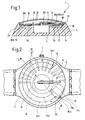
- FIGS. 1 and 2 a timepiece according to the invention will be described below, represented here by the general reference 1.
- the timepiece 1 conventionally comprises a box 2 made for example of a plastic material, by a conventional injection technique.
- the part 1 also comprises a horometric movement 4 which is housed inside the box 2 and which is here mechanically coupled to indicators 6 and 8 formed respectively by a minute hand and by an hour hand.
- the part 1 is made watertight by the provision of a lens 10 fixedly mounted on the box 2, in a conventional manner, for example by a gluing or ultrasonic welding technique.
- the part 1 is further provided with means for transmitting an electromagnetic signal, these means comprising electronic means for supplying a signal, referenced 12, and at least one transmitting antenna 14, coupled to the electronic means 12.
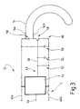
- the electronic means 12 for supplying the signal are shown in more detail in FIG. 3 and will be described later.
- the antenna 14 is constituted by two branches 14a and 14b each having a partially circular shape, these branches 14a and 14b being respectively connected, at one of their ends , referenced 14c, to electrical connection tracks 16a and 16b. These branches 14a and 14b are also connected to each other, at their other end referenced 14d, by a loop 18.
- the antenna 14 is formed, here directly, on a first face 20a of a support plate 20 of essentially planar shape, disposed inside the box 2 and locked in the latter, on the one hand, against a shoulder 22 formed directly in the box 2, and on the other hand, by the free end, not referenced, of the glass 10.
- the support plate 20 which is made of an insulating material, such as epoxy, has an outer contour which corresponds substantially to that formed by the upper cavity 24 formed in the box 2 for the arrangement of the 8 and 8 hour hands, respectively. minutes 6, and for embedding the glass 10.
- the support plate 20 therefore has a circular contour, and it is pierced in its center with an orifice 20c allowing the passage of the barrels, not referenced, of the needles 6 and 8.
- the support plate 20 which has a shape of thin pellet (about 0.35 mm thick), has a shape similar to a dial, and it is placed in the box in place of it.
- the antenna 14 is produced by a thin metal layer deposited on the face 20a of the support plate 20.
- the electronic means 12 for supplying the signal are also mounted on the support plate 20 , and are anchored on the face 20a of this plate.
- the electronic means 12 for supplying the signal are arranged on the face of the support plate 20 on which the antenna 14 is formed. In another embodiment, not shown, these electronic means 12 are integrated into the movement 4.
- the antenna 14 is produced by photolithographic etching of an electroconductive layer, such as a copper layer covered with a gold deposit, this layer being deposited on the face 20a of the support plate 20.
- an electroconductive layer such as a copper layer covered with a gold deposit
- These etching techniques also called structuring of thin or thin layers (less than a millimeter) deposited on a substrate, such as plate 20, are conventional in themselves, and will not be described here in more detail.
- connection tracks 16a and 16b are provided on the support plate 20, in the same layer as that forming the antenna 14, therefore over the same thickness. These electrical connection tracks 16a and 16b provide an electrical connection between the antenna 14 and the electronic means 12 for supplying the signal.
- the support plate 20 which acts as a dial is placed directly above the movement 4.
- the antenna 14 extends in a curved fashion along the periphery of the support plate 20, and in particular along the periphery of the cavity 24 of the box 2, outside the movement 4.
- the face 20a of the support plate 20 is oriented opposite the movement 4.
- the antenna 14 as well as the electronic means 12 for supplying the signal are arranged around the movement 4 outside and outside of it, in an annular housing 26 provided for this purpose in the box 2
- the antenna 14 and the electronic means 12 for supplying the signal are therefore arranged outside the surface or frontal projection of the movement 4, so that in the axial direction there is no possible interference between the movement 4 and the means 12, 14 for transmitting the electromagnetic signal.
- the part 1 further comprises a capacitive plane 30 which is formed on a second face 20b of the support plate 20, this face 20b being opposite to the first face 20a on which the antenna is formed 14.
- the capacitive plane 30 is constituted by a set of streaks 32, two of which have only been referenced here. These ridges 32 are arranged adjacent to each other and converge, in this embodiment, towards the center of the support plate 20, that is to say towards the orifice 20c for passage of the needle barrels. 6 and 8.
- the ridges 32 forming the capacitive plane 30 are formed on the second face 20b of the support plate 20 by the same photolitic deposition and structuring technique as the antenna 14, in a thin electroconductive layer of the same nature.
- the capacitive plane 30 is arranged in line with the antenna 14, so that it covers it almost entirely.
- the capacitive plane 30 provides effective protection against parasitic capacitances, due for example to the bringing together of the user's free hand towards the timepiece, in particular during the actuation of the means 12, 14 for transmitting the electromagnetic signal.
- the capacitive plane 30 being formed on the visible upper face 20b of the support plate 20 forming a dial, this capacitive plane 30 also constitutes patterns of an ornamental nature.
- the antenna 14 has an extension which is formed by a track 36 electrically connected to the so-called lower layer forming the antenna 14 and which is formed, in the vicinity of the center of the support plate 20, on the second face 20b forming here upper face.
- the track 36 therefore crosses the support plate 20 via a metallization and an orifice, not shown, to come into contact with the layer forming the antenna 14 on the face 20a, here forming the underside.
- a ground plane 38, electrically connected to the movement 4, is further provided on the upper face 20b, in the vicinity of the capacitive plane 30.
- the circuit 12 comprises two supply lines 40a and 40b respectively (here positive and negative respectively) constituted by electrical connection wires connected to an electrical supply, not shown, of movement 4.
- the electronic means 12 also include a transmitter logic circuit 42 connected between the two supply lines 40a and 40b respectively.
- the transmitting logic circuit 42 receives, from a line 44 likewise connected to a time base not shown of the time movement 4, a clock signal calibrated on a frequency, such as for example 32 kHz.
- the rod in the form of a switch, is connected to the supply line 40b, upstream from the connection point between the transmitter logic circuit 42 and the supply line 40b.
- a first resistor 46 which is itself connected to the base of a transistor 48.
- connection between the resistor 46 and the transistor 48 forms an intermediate line 50. Between this line 50 and the supply line 40b are respectively connected, on the one hand, a resistor 52 and, on the other hand, a capacitor 54. A second capacitor, referenced 56, is in turn connected between the two supply lines 40a and 40b.
- a third capacitor 58 is connected between the two electrical connections 16a and 16b of the antenna 14.
- the first electrical connection 16a of the antenna 14 is therefore connected between the first supply line 40a and the capacitor 58, while the second connection track 16b is connected between capacitor 58 and the collector of transistor 48.
- the emitter of transistor 48 is in turn connected to the second supply line 40b via a resistor 60.
Landscapes
- Physics & Mathematics (AREA)
- General Physics & Mathematics (AREA)
- Electric Clocks (AREA)
- Electromechanical Clocks (AREA)
Claims (12)
- Zeitmeßgerät der Bauart mit einem Gehäuse (2), mit einem Uhrwerk (4), das im Innern des Gehäuses (2) untergebracht ist, und mit Signalaussendemitteln, umfassend elektronische Mittel (12) zum Bereitstellen des Signals, und mindestens eine Sendeantenne (14), die an die elektronischen Mittel (12) angekoppelt ist und aus einer dünnen metallischen Schicht im wesentlichen ebener Form gebildet ist, aufgebracht auf einer ersten Seite (20a) einer, im Innern des Gehäuses (2) befindlichen Supportplatte (20), dadurch gekennzeichnet, daß es ferner eine kapazitive Ebene (30) umfaßt, ausgearbeitet auf einer zweiten Seite (20b) der Supportplatte (20) gegenüber der ersten Seite (20a), daß die Supportplatte (20) dem Zifferblatt gegenüberliegt und daß die Sendeantenne (14) außerhalb der frontalen Projektion des Uhrwerks (4) auf das Zifferblatt angeordnet ist.
- Zeitmeßgerät nach Anspruch 1, dadurch gekennzeichnet, daß die elektronischen Mittel (12) für das Bereitstellen des Signals ebenfalls auf der Supportplatte (20) montiert sind.
- Zeitmeßgerät nach Anspruch 2, dadurch gekennzeichnet, daß die elektronischen Mittel (12) für das Bereitstellen des Signals auf der ersten Seite (20a) der Supportplatte (20), auf der die Sendeantenne (14) ausgearbeitet ist, angeordnet sind.
- Zeitmeßgerät nach einem der Ansprüche 1 bis 3, dadurch gekennzeichnet, daß die Sendeantenne (14) durch photolithographische Ätzung einer elektrisch leitenden Schicht hergestellt ist, die auf der ersten Seite (20a) der Supportplatte (20) aufgebracht ist.
- Zeitmeßgerät nach Anspruch 3, dadurch gekennzeichnet, daß die Supportplatte (20) elektrische Verbindungsbahnen (16a,16b) umfaßt, die die Verbindung zwischen der Sendeantenne (14) und den elektronischen Mitteln (12) für die Bereitstellung des Signals sicherstellen.
- Zeitmeßgerät nach Anspruch 5, dadurch gekennzeichnet, daß die elektrischen Verbindungsbahnen (16a,16b) in derselben Schicht strukturiert sind wie jene, die die Sendeantenne (14) bildet.
- Zeitmeßgerät nach einem der vorangehenden Ansprüche, dadurch gekennzeichnet, daß die Sendeantenne (14) von zwei Armen (14a,14b) teilrunder Form gebildet ist, die mit einem ihrer Enden (14c) mit den elektrischen Anschlüssen (16a,16b) verbunden sind und mit ihrem anderen Ende (14d) miteinander über eine Schleife (18).
- Zeitmeßgerät nach einem der vorangehenden Ansprüche, dadurch gekennzeichnet, daß die kapazitive Ebene (30) durch eine Gruppe von Streifen (32) gebildet ist, die nebeneinanderliegend und in Richtung des Zentrums der Supportplatte (20) konvergierend ausgebildet sind.
- Zeitmeßgerät nach Anspruch 8, dadurch gekennzeichnet, daß die kapazitive Ebene (30) gegenüber der Sendeantenne (14) ausgebildet ist.
- Zeitmeßgerät nach einem der vorangehenden Ansprüche, dadurch gekennzeichnet, daß die Sendeantenne (14) sich längs der Peripherie der Supportplatte (20) erstreckt.
- Zeitmeßgerät nach einem der vorangehenden Ansprüche, dadurch gekennzeichnet, daß die erste Seite (20a), welche die Sendeantenne (14) abstützt, gegenüber dem Uhrwerk (4) orientiert ist.
- Zeitmeßgerät nach Anspruch 11, dadurch gekennzeichnet, daß die kapazitive Ebene (30) Motive ornamentalen Charakters bildet.
Applications Claiming Priority (2)
| Application Number | Priority Date | Filing Date | Title |
|---|---|---|---|
| CH03934/92A CH686107B5 (fr) | 1992-12-23 | 1992-12-23 | Pièce d'horlogerie comportant une antenne d'émission d'un signal électromagnétique. |
| CH3934/92 | 1992-12-23 |
Publications (2)
| Publication Number | Publication Date |
|---|---|
| EP0603721A1 EP0603721A1 (de) | 1994-06-29 |
| EP0603721B1 true EP0603721B1 (de) | 1997-06-11 |
Family
ID=4266642
Family Applications (1)
| Application Number | Title | Priority Date | Filing Date |
|---|---|---|---|
| EP93120193A Expired - Lifetime EP0603721B1 (de) | 1992-12-23 | 1993-12-15 | Uhr mit einer ein elektromagnetisches Signal aussendenden Antenne |
Country Status (6)
| Country | Link |
|---|---|
| US (1) | US5367502A (de) |
| EP (1) | EP0603721B1 (de) |
| JP (1) | JP3443148B2 (de) |
| CN (1) | CN1034889C (de) |
| CH (1) | CH686107B5 (de) |
| DE (1) | DE69311515T2 (de) |
Families Citing this family (17)
| Publication number | Priority date | Publication date | Assignee | Title |
|---|---|---|---|---|
| DE29504027U1 (de) * | 1995-03-09 | 1995-05-18 | TAMSIT Vertriebsgesellschaft mbH, 22047 Hamburg | Elektronische Uhr, insbesondere Taschen- oder Armbanduhr |
| DE69520351T2 (de) * | 1995-05-05 | 2001-10-11 | Eta S.A. Fabriques D'ebauches, Grenchen/Granges | Antennenstruktur für eine Uhr |
| JPH09307329A (ja) * | 1996-05-14 | 1997-11-28 | Casio Comput Co Ltd | アンテナ及びその製造方法並びにアンテナを備えた電 子機器又は電子時計 |
| CH690525A5 (fr) * | 1996-11-22 | 2000-09-29 | Ebauchesfabrik Eta Ag | Pièce d'horlogerie comportant une antenne de réception et/ou de transmission d'un signal radio-diffusé. |
| US5881021A (en) * | 1997-03-10 | 1999-03-09 | Dreamco Enterprises Inc. | Quick charge capacitor powered non-interruptible wearable personal security alarm |
| DE19724708A1 (de) * | 1997-06-13 | 1998-12-17 | Junghans Uhren Gmbh | Kleinuhr mit Transponder |
| US6356512B1 (en) * | 1998-07-20 | 2002-03-12 | Asulab S.A. | Subassembly combining an antenna and position sensors on a same support, notably for a horological piece |
| JP2003046316A (ja) * | 2001-08-03 | 2003-02-14 | Seiko Epson Corp | 非接触データ通信機能を備えた腕装着型電子機器及び非接触データ通信システム |
| DE60217660T2 (de) * | 2002-07-02 | 2007-11-22 | CSEM Centre Suisse d`Electronique et de Microtechnique S.A. - Recherche et Développement | Uhrwerk mit Antenne |
| ATE350693T1 (de) * | 2004-04-24 | 2007-01-15 | Winwatch Sa | Verfahren zum integrieren mindestens eines elektronischen moduls in oder auf dem glas einer uhr |
| JP5786555B2 (ja) * | 2011-02-23 | 2015-09-30 | セイコーエプソン株式会社 | アンテナ装置、電子機器および電子時計 |
| CN104137005B (zh) * | 2012-02-29 | 2016-12-21 | 精工爱普生株式会社 | 天线内置式电子表 |
| EP3343451B1 (de) | 2016-12-29 | 2022-09-21 | The Swatch Group Research and Development Ltd | Tragbarer gegenstand, der eine nahfeldverbindungsvorrichtung umfasst |
| EP3343450B1 (de) | 2016-12-29 | 2020-02-05 | The Swatch Group Research and Development Ltd | Tragbarer gegenstand, der eine nahfeldverbindungsvorrichtung umfasst |
| TWI704719B (zh) * | 2018-05-16 | 2020-09-11 | 廣達電腦股份有限公司 | 穿戴式裝置 |
| CN108762057B (zh) * | 2018-06-27 | 2021-02-12 | 成都天奥电子股份有限公司 | 一种金属表壳的手表 |
| EP4092493A1 (de) | 2021-05-21 | 2022-11-23 | ETA SA Manufacture Horlogère Suisse | Armbanduhr mit einem nahfeld-kommunikationsgerät |
Family Cites Families (15)
| Publication number | Priority date | Publication date | Assignee | Title |
|---|---|---|---|---|
| US4232512A (en) * | 1976-12-27 | 1980-11-11 | Citizen Watch Co., Ltd. | Solid state watch module construction |
| JPS53107366A (en) * | 1977-03-01 | 1978-09-19 | Citizen Watch Co Ltd | Electronic watch having matrix drive display |
| JPS5473074A (en) * | 1977-11-22 | 1979-06-12 | Seiko Epson Corp | Electronic watch |
| JPS56169401A (en) * | 1980-05-31 | 1981-12-26 | Shuichi Sakai | Antenna for wrist watch type receiver |
| USRE32369E (en) * | 1980-11-17 | 1987-03-10 | Ball Corporation | Monolithic microwave integrated circuit with integral array antenna |
| US4442590A (en) * | 1980-11-17 | 1984-04-17 | Ball Corporation | Monolithic microwave integrated circuit with integral array antenna |
| US4490721A (en) * | 1980-11-17 | 1984-12-25 | Ball Corporation | Monolithic microwave integrated circuit with integral array antenna |
| DE3177208D1 (de) * | 1980-11-17 | 1990-10-04 | Ball Corp | Integrierter monolithischer mikrowellenschaltkreis mit integraler antennenanordnung. |
| DE3234601A1 (de) * | 1982-09-17 | 1984-03-22 | Siemens AG, 1000 Berlin und 8000 München | Anordnung zur markierung von personen und objekten |
| FR2621179B1 (fr) * | 1987-09-25 | 1990-01-19 | Alcatel Thomson Radiotelephone | Antenne pour recepteur miniature notamment pour recepteur en forme de boitier de montre |
| CH672870B5 (de) * | 1988-04-26 | 1990-07-13 | Ebauchesfabrik Eta Ag | |
| US4847818A (en) * | 1988-10-31 | 1989-07-11 | Timex Corporation | Wristwatch radiotelephone |
| US4903254A (en) * | 1989-08-31 | 1990-02-20 | Haas David J | Time indicator enhancement method |
| US5179733A (en) * | 1990-04-23 | 1993-01-12 | Seiko Epson Corporation | Wristwatch band with radio antenna |
| CH679356B5 (de) * | 1990-06-07 | 1992-08-14 | Ebauchesfabrik Eta Ag |
-
1992
- 1992-12-23 CH CH03934/92A patent/CH686107B5/fr not_active IP Right Cessation
-
1993
- 1993-12-15 EP EP93120193A patent/EP0603721B1/de not_active Expired - Lifetime
- 1993-12-15 DE DE69311515T patent/DE69311515T2/de not_active Expired - Lifetime
- 1993-12-22 CN CN93121274A patent/CN1034889C/zh not_active Expired - Lifetime
- 1993-12-22 US US08/171,638 patent/US5367502A/en not_active Expired - Lifetime
- 1993-12-24 JP JP34599593A patent/JP3443148B2/ja not_active Expired - Fee Related
Also Published As
| Publication number | Publication date |
|---|---|
| CN1034889C (zh) | 1997-05-14 |
| CH686107GA3 (fr) | 1996-01-15 |
| JP3443148B2 (ja) | 2003-09-02 |
| CN1090067A (zh) | 1994-07-27 |
| CH686107B5 (fr) | 1996-07-15 |
| US5367502A (en) | 1994-11-22 |
| JPH06230151A (ja) | 1994-08-19 |
| EP0603721A1 (de) | 1994-06-29 |
| DE69311515D1 (de) | 1997-07-17 |
| DE69311515T2 (de) | 1998-01-22 |
Similar Documents
| Publication | Publication Date | Title |
|---|---|---|
| EP0603721B1 (de) | Uhr mit einer ein elektromagnetisches Signal aussendenden Antenne | |
| EP0766152B1 (de) | Uhr mit einer Antenne | |
| EP1093098B1 (de) | Antennenstruktur die ein Gehäuse bildet für elektronische Komponente eines tragbaren Gerätes | |
| EP1519452B1 (de) | Tragbares elektronisches Gerät mit zumindest einem angepassten Betätigungselement zum Übertragen von elektrischen Signalen | |
| EP1407513B1 (de) | Antenne für armbanduhr | |
| EP1660953B1 (de) | Metallgehäuse-uhr mit einem elektronischen modul zum einlesen von informationen | |
| EP1378805B1 (de) | Uhrwerk mit Antenne | |
| EP1489471A1 (de) | Erdung von einer gedruckten Schaltung eingestellt in einen Armband elektronischen Gerät | |
| CH690525A5 (fr) | Pièce d'horlogerie comportant une antenne de réception et/ou de transmission d'un signal radio-diffusé. | |
| FR2505105A1 (fr) | Bracelet radio am | |
| CH672870B5 (de) | ||
| EP1315234A1 (de) | VHF-Empfangsantenne integriert in das Armband einer tragbaren elektronischen Vorrichtung | |
| EP0360140B1 (de) | Eine ganz oder teilweise den Aufbau zeigende Skelettuhr | |
| EP1513220A1 (de) | Patch-Antenne integriert in einer Armbanduhr | |
| EP1519453B1 (de) | Tragbares elektronisches Gerät mit zumindest einer angepassten Eingangs/Ausgangsanschlussklemme zur Kommunikation mit einer elektronischen Einheit in diesem Gerät | |
| WO1997015899A1 (fr) | Dispositif hybride a contacts affleurants et a production de signaux acoustiques, et procede de fabrication | |
| EP0844685B1 (de) | Uhr mit Antenne zum Empfangen und/oder Aussenden von Funksignalen | |
| EP1431847B1 (de) | Tragbares elektronisches Gerät, insbesondere Uhr, mit einer Antenne, die aus einer Spule mit grossem Diameter gebildet ist | |
| EP0099308A1 (de) | Quarzuhr | |
| EP1318437A1 (de) | Uhr mit Transponder, der wenigstens teilweise in einem Bedienungselement eingebaut ist | |
| EP4006653B1 (de) | Armbanduhrengehäuse, das eine kontrollvorrichtung einer nahfeldkommunikationsvorrichtung umfasst | |
| EP0954051B1 (de) | Schlitzantenne, insbesondere für eine Uhr | |
| EP3669235B1 (de) | Elektromechanisches uhrenmodul mit einer antenne | |
| EP0041245B1 (de) | Elektronisches Uhrwerk mit elektro akustischem Übertrager | |
| CH686696B5 (fr) | Montre munie d'une antenne,notamment du type montre-bracelet. |
Legal Events
| Date | Code | Title | Description |
|---|---|---|---|
| PUAI | Public reference made under article 153(3) epc to a published international application that has entered the european phase |
Free format text: ORIGINAL CODE: 0009012 |
|
| AK | Designated contracting states |
Kind code of ref document: A1 Designated state(s): DE FR GB IT |
|
| 17P | Request for examination filed |
Effective date: 19940711 |
|
| 17Q | First examination report despatched |
Effective date: 19960206 |
|
| GRAG | Despatch of communication of intention to grant |
Free format text: ORIGINAL CODE: EPIDOS AGRA |
|
| GRAH | Despatch of communication of intention to grant a patent |
Free format text: ORIGINAL CODE: EPIDOS IGRA |
|
| GRAH | Despatch of communication of intention to grant a patent |
Free format text: ORIGINAL CODE: EPIDOS IGRA |
|
| GRAA | (expected) grant |
Free format text: ORIGINAL CODE: 0009210 |
|
| AK | Designated contracting states |
Kind code of ref document: B1 Designated state(s): DE FR GB IT |
|
| REF | Corresponds to: |
Ref document number: 69311515 Country of ref document: DE Date of ref document: 19970717 |
|
| ITF | It: translation for a ep patent filed | ||
| GBT | Gb: translation of ep patent filed (gb section 77(6)(a)/1977) |
Effective date: 19970819 |
|
| PLBE | No opposition filed within time limit |
Free format text: ORIGINAL CODE: 0009261 |
|
| STAA | Information on the status of an ep patent application or granted ep patent |
Free format text: STATUS: NO OPPOSITION FILED WITHIN TIME LIMIT |
|
| 26N | No opposition filed | ||
| REG | Reference to a national code |
Ref country code: GB Ref legal event code: IF02 |
|
| PGFP | Annual fee paid to national office [announced via postgrant information from national office to epo] |
Ref country code: IT Payment date: 20081218 Year of fee payment: 16 |
|
| PG25 | Lapsed in a contracting state [announced via postgrant information from national office to epo] |
Ref country code: IT Free format text: LAPSE BECAUSE OF NON-PAYMENT OF DUE FEES Effective date: 20091215 |
|
| PGFP | Annual fee paid to national office [announced via postgrant information from national office to epo] |
Ref country code: DE Payment date: 20121122 Year of fee payment: 20 |
|
| PGFP | Annual fee paid to national office [announced via postgrant information from national office to epo] |
Ref country code: GB Payment date: 20121122 Year of fee payment: 20 |
|
| PGFP | Annual fee paid to national office [announced via postgrant information from national office to epo] |
Ref country code: FR Payment date: 20130130 Year of fee payment: 20 |
|
| REG | Reference to a national code |
Ref country code: DE Ref legal event code: R071 Ref document number: 69311515 Country of ref document: DE |
|
| REG | Reference to a national code |
Ref country code: GB Ref legal event code: PE20 Expiry date: 20131214 |
|
| PG25 | Lapsed in a contracting state [announced via postgrant information from national office to epo] |
Ref country code: DE Free format text: LAPSE BECAUSE OF EXPIRATION OF PROTECTION Effective date: 20131217 Ref country code: GB Free format text: LAPSE BECAUSE OF EXPIRATION OF PROTECTION Effective date: 20131214 |