EP0603729A2 - Chaussure de ski - Google Patents
Chaussure de ski Download PDFInfo
- Publication number
- EP0603729A2 EP0603729A2 EP93120221A EP93120221A EP0603729A2 EP 0603729 A2 EP0603729 A2 EP 0603729A2 EP 93120221 A EP93120221 A EP 93120221A EP 93120221 A EP93120221 A EP 93120221A EP 0603729 A2 EP0603729 A2 EP 0603729A2
- Authority
- EP
- European Patent Office
- Prior art keywords
- shell
- flap
- ski boot
- cable
- boot according
- Prior art date
- Legal status (The legal status is an assumption and is not a legal conclusion. Google has not performed a legal analysis and makes no representation as to the accuracy of the status listed.)
- Withdrawn
Links
Images


Classifications
-
- A—HUMAN NECESSITIES
- A43—FOOTWEAR
- A43B—CHARACTERISTIC FEATURES OF FOOTWEAR; PARTS OF FOOTWEAR
- A43B5/00—Footwear for sporting purposes
- A43B5/04—Ski or like boots
- A43B5/0427—Ski or like boots characterised by type or construction details
- A43B5/0435—Adjustment of the boot to the foot
- A43B5/0443—Adjustment of the boot to the foot to the instep of the foot, e.g. metatarsals; Metatarsal clamping devices
Definitions
- the present invention relates to a ski boot, particularly of the type which can be opened at the rear or at the center and comprising a shell, provided with a front longitudinal opening, with which at least one quarter is associated.
- Closed-shell boots are known in which this securing is achieved using cables or straps arranged inside the shell and connected to tensioning means.
- This structure entails, especially at the regions of the instep and of the upper metatarsus, the forming of localized pressure areas due to the use of said securing cables or straps which pass above these foot regions.
- the aim of the present invention is to overcome the above technical problems, by providing a ski boot which allows to achieve optimum surrounding and securing of the foot, maintaining optimum comfort for the foot and improving the technical and aesthetic features of the boot.
- Another important object is to provide a ski boot which optimally surrounds the foot and the leg, particularly the instep and upper metatarsal region of the foot, ensuring optimum comfort even when the boot is closed and locked.
- a further object is to facilitate the closure of the boot for the skier.
- Another important object is to provide a ski boot which is effectively waterproof and snowproof.
- Another object is to provide a ski boot which is reliable and safe in use and has low manufacturing costs.
- a ski boot which comprises a shell provided with a front longitudinal opening, characterized in that it comprises at least one flap which surrounds said opening and is associated with said shell at a first side, said at least one flap interacting, at the second side, with securing means and with means for permanent connection to said shell.
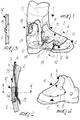
- the reference numeral 1 designates the ski boot, which comprises a shell 2 having overlapping flaps or provided with a longitudinal opening 3 formed at the region 4 which affects the upper metatarsal region and, at least partially, the foot instep.
- At least one quarter 5 is associated with the shell 2, and a flap 6 is associated at the longitudinal opening 3. Flap 6 surrounds the opening and has a first side 7 which affects the internal lateral region of the foot.
- First side 7 is associated with the shell 2, or rigidly coupled to the shell 2 for example by means of adapted first rivets 8.
- the flap 6 also has a second side 9 which is arranged approximately laterally to the outer region of the foot and interacts with adjustable securing means and with means for permanent connection to the shell 2.
- Said securing means are, for example, constituted by one or more traction elements, such as a cable 11 which is associated at one end with an adjustment device such as, for example, a conventional knob 10 having a threaded axial seat for a complementarily threaded bush which is associated with the end of cable 11.
- the cable exits from the second side 9 and affects an adapted guide 12 which is arranged at an adapted first seat 13 formed on the shell 2 and is rigidly coupled to the shell for example by means of an adapted second rivet 14.
- the cable 11 is advantageously arranged within an adapted sheath 15.
- the assembly thus formed is then guided inside the shell 2, possibly passing transversely below an insole 16.
- the sheath accommodating the cable is then made to pass outside the shell 2, for example at adapted first lateral holes 17, to connect it to means for tensioning the cable, such as for example vertical levers 18, or winders.
- the use of the present invention is as follows: the particular connection of the flap 6, at the first side 7 and at the second side 9, to the shell 2 by virtue of the securing means and of the connecting means allows, if the tensioning means are not activated, to nonetheless keep the flap 6 connected to the shell, allowing its loosening for foot entry but preventing its overturning.
- the flap 6 can be made of a material having a different rigidity with respect to the shell and the quarter, allows to achieve optimum surrounding of the foot in the instep and upper metatarsal regions while allowing an extremely easy insertion of the foot, since the means for securing and connection to the shell do not affect the region on which the longitudinal opening 3 is formed.
- the particular arrangement of the securing and connection means allows the boot to have a highly linear profile with no protruding elements which might interact with the snow or catch in other elements while the boot is being carried.
- the invention has thus achieved the intended aim and objects, a ski boot having been obtained in which optimum surrounding of the foot is achieved by using securing means and means for connecting the flap to the shell which facilitate putting on the boot and are integrated in the profile of the boot, maintaining a continuous connection between the various elements to be secured, in order to facilitate the closure operation.
- boot according to the invention is susceptible to numerous modifications and variations, all of which are within the scope of the same inventive concept.
- figure 5 illustrates a ski boot 101 comprising a shell 102 provided with a front longitudinal opening 103 at the instep and upper metatarsal region 104.
- a flap 106 having a first side 107 rigidly coupled at the shell 102 by means of adapted first rivets 108 and a second side 109 which interacts with adjustable means for securing and for connection to said shell.
- Said means are constituted by a cable 111 which has a first end 119 rigidly coupled to the shell 102 at the part on which the first side 107 is superimposed.
- Said cable 111 then affects the shell 102, one or more times, transversely and externally, and is guided at adapted first guides 120 and second guides 121 which are alternatively fixed respectively at the shell 102, in a region adjacent to the second side 109, and inside the flap 106, in an adapted second seat 122 which is transverse to said flap.
- the second end 123 of the cable 111 is instead connected to tensioning means, such as a winder 118, or to a lever which is advantageously arranged to the rear of the quarter 105.
- connection means and the shell securing means constituted by the cable 111, tend to lower the flap 106 at the outer surface of the shell 102, preventing the overturning of the second side 109 of the flap 106 when the tensioning means are deactivated.
- first guides 120 can be temporarily arranged at the second seat 122, this solution also allows to improve the aesthetic profile of the boot, since the flap 106 has no protruding elements.
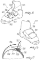
- Figures 7 and 8 illustrate a further embodiment for a ski boot 201, which comprises a shell 202 on which a front longitudinal opening 203 is formed at the instep and upper metatarsal region 204.
- At least one flap 206 is arranged at the region 204 and has a first side 207 which is rigidly coupled to the shell 202 by means of adapted first rivets 208.
- the flap 206 has a second side 209 which is slidingly associated with the outer lateral surface of the shell 202 by using adapted permanent-connection means, such as second rivets 214 which are slideable within adapted slots 224 formed transversely to the shell 202.
- adapted permanent-connection means such as second rivets 214 which are slideable within adapted slots 224 formed transversely to the shell 202.
- the securing means comprise an internally threaded bush 225 which is arranged in the interspace between the outer lateral surface of the shell 202 and the inner lateral surface of the flap 206, proximate to the first side 207 of the flap 206.
- the bush 225 is rigidly coupled to the overlying flap 206, and a complementarily threaded end of a traction element, such as a cable 211, is associated with the bush.
- the cable 211 is contained, at its other end, within a tube 234 which is transversely pivoted, by means of a first pivot 226, between the wings 227a and 227b of a lever 218.
- the lever 218 is transversely pivoted, at one end, by means of a second pivot 228, to the wings of a base 229 which is rigidly coupled to the underlying shell 202 by means of adapted second rivets 214.
- An adjustment element such as a knob 235, protrudes from the tube 234 and is rigidly coupled to the cable 211 at the end which is contained in the tube.
- Rotation of the knob 235 thus causes the cable 211 and particularly its threaded end which engages the bush 225, to rotate rigidly with the knob.
- the working length of the cable 211 is thus adjusted.
- An adapted third seat 230 for accommodating the lever 218 is formed on the flap 206, starting from the second side 209 and at the cable 211 and at the lever 218.
- the third seat can be partially closed by using an adapted covering flap 231 which is pivoted at the first pivot 226 at one end and is slideable, at its other end, through an adapted seat formed on the bush 225 in the interspace between the internal lateral surface of the flap 206 and the bush.
- the third seat 230 formed on the flap 206 is closed by a cross-member 232 at the second side 209.
- the base 229 is arranged at said third seat and has, at its longitudinal ends, adapted tabs 233 which surmount the flap 206 so as to both keep said flap adjacent to the outer lateral surface of the shell 202 and allow the sliding of the second side 209.
- the longitudinal extension of the base 229 is of course shorter than that of the third seat 230, as shown in figure 10.
- Figures 11 and 12 illustrate a further embodiment for a ski boot 301, which comprises a shell 302 provided with a longitudinal opening 303 at the instep and upper metatarsal region 304.
- a flap 306, and adapted fourth seats 334 are formed proximate to its first side 307 for pawls 335 which interact in a ratchet-like manner with an underlying rack 336 formed at one end of a band 337 which is pivoted, at its other end, by means of a first pivot 326, between the wings 327 of a lever 318 which is in turn pivoted, at one end, by means of a second pivot 328, to the wings which protrude from a base 329 rigidly coupled to the shell 302 by means of adapted second rivets 314.
- the second side 309 of the flap 306 is associated with the shell 302 by means of adapted third rivets 338 which act in adapted slots 324 formed at the shell.
- the flap 306 has a tab 339 which is consequently located at the third seat 330 in order to also accommodate the lever 318.
- Figures 13 and 14 illustrate a further embodiment of a ski boot which comprises a shell 402 of the type having overlapping flaps and thus in any case allowing, at the instep and upper metatarsal region 404, to move the flaps away from each other in order to insert and remove the foot.
- a flap 406, the first side 407 whereof is slidingly associated with the underlying shell 402 by using adapted first rivets 408 rigidly coupled to the shell and are slideable at adapted slots 424 formed transversely to the flap 406.
- the second side 409 of the flap 406 is rigidly coupled to the shell 402 by means of adapted second rivets 414, proximate to which a base 429 is rigidly coupled to the shell 402; the end of a lever 418 is pivoted to said base.
- a means for the micrometric takeup of a traction element, such as a cable 411, is associated with said lever 418; said takeup means is constituted for example by a knob 410.
- the cable 411 passes at an adapted second seat 422 formed on the flap 406 and is then locked, at one end, at the first rivets 408.
- Figures 15-17 illustrate a ski boot 501 according to a sixth aspect of the invention.
- the ski boot 501 comprises a shell 502 having two overlapping flaps 503 and 504.
- a closure flap 506 is connected to the flap 504 and has at least one lever 527 pivoted at the free end.
- the lever 527 is also pivoted, at one end, to a slider 528 having a pawl 535.
- a rack 536 is connected to the shell flap 503 and engages the slider 528 and pawl 535 assembly.
- the slider 528 By operating the pawl 535, the slider 528 can be selectively positioned on the rack 536 thereby selecting the degree of closure of the closure flap 506 by the lever 527.
- closure flap 506 is adapted to completely embrace the slider and rack pawl assembly, in the closed position, as shown in the figures.
Landscapes
- Health & Medical Sciences (AREA)
- General Health & Medical Sciences (AREA)
- Physical Education & Sports Medicine (AREA)
- Footwear And Its Accessory, Manufacturing Method And Apparatuses (AREA)
Applications Claiming Priority (2)
| Application Number | Priority Date | Filing Date | Title |
|---|---|---|---|
| ITTV920158 | 1992-12-22 | ||
| ITTV920158A IT1257747B (it) | 1992-12-22 | 1992-12-22 | Struttura di scarpone da sci a calzabilita' migliorata |
Publications (2)
| Publication Number | Publication Date |
|---|---|
| EP0603729A2 true EP0603729A2 (fr) | 1994-06-29 |
| EP0603729A3 EP0603729A3 (fr) | 1994-08-03 |
Family
ID=11419154
Family Applications (1)
| Application Number | Title | Priority Date | Filing Date |
|---|---|---|---|
| EP19930120221 Withdrawn EP0603729A3 (fr) | 1992-12-22 | 1993-12-15 | Chaussure de ski |
Country Status (3)
| Country | Link |
|---|---|
| EP (1) | EP0603729A3 (fr) |
| JP (1) | JPH07298901A (fr) |
| IT (1) | IT1257747B (fr) |
Cited By (2)
| Publication number | Priority date | Publication date | Assignee | Title |
|---|---|---|---|---|
| WO1995011602A1 (fr) * | 1993-10-28 | 1995-05-04 | Koflach Sport Gesellschaft M.B.H. | Chaussure de ski |
| FR2734690A1 (fr) * | 1995-05-30 | 1996-12-06 | Rossignol Sa | Chaussure pour la pratique du ski de fond |
Family Cites Families (4)
| Publication number | Priority date | Publication date | Assignee | Title |
|---|---|---|---|---|
| FR1587712A (fr) * | 1968-08-27 | 1970-03-27 | ||
| CH508363A (it) * | 1969-12-24 | 1971-06-15 | Secondo Sergio | Scarpa da sci |
| US4078322A (en) * | 1976-08-04 | 1978-03-14 | Engineered Sports Products, Inc. | Ski boot |
| IT1225397B (it) * | 1988-08-02 | 1990-11-13 | Nordica Spa | Struttura di scafo, particolarmente per scarponi da sci ad entrata an teriore |
-
1992
- 1992-12-22 IT ITTV920158A patent/IT1257747B/it active IP Right Grant
-
1993
- 1993-12-15 EP EP19930120221 patent/EP0603729A3/fr not_active Withdrawn
- 1993-12-22 JP JP5324487A patent/JPH07298901A/ja active Pending
Cited By (2)
| Publication number | Priority date | Publication date | Assignee | Title |
|---|---|---|---|---|
| WO1995011602A1 (fr) * | 1993-10-28 | 1995-05-04 | Koflach Sport Gesellschaft M.B.H. | Chaussure de ski |
| FR2734690A1 (fr) * | 1995-05-30 | 1996-12-06 | Rossignol Sa | Chaussure pour la pratique du ski de fond |
Also Published As
| Publication number | Publication date |
|---|---|
| IT1257747B (it) | 1996-02-13 |
| ITTV920158A0 (it) | 1992-12-22 |
| JPH07298901A (ja) | 1995-11-14 |
| EP0603729A3 (fr) | 1994-08-03 |
| ITTV920158A1 (it) | 1994-06-22 |
Similar Documents
| Publication | Publication Date | Title |
|---|---|---|
| US5249377A (en) | Ski boot having tensioning means in the forefoot region | |
| US5319868A (en) | Shoe, especially an athletic, leisure or rehabilitation shoe having a central closure | |
| US5502902A (en) | Shoe with central rotary closure | |
| US4800659A (en) | foot-clamping structure for shoes and boots | |
| US20030192204A1 (en) | Expandable shoe and shoe assemblies | |
| US20010007178A1 (en) | High boot with lace-tightening device | |
| US20020174570A1 (en) | Articulated ski boot | |
| EP0071055B1 (fr) | Chaussure, en particulier chaussure de ski, comportant un dispositif de réglage de la flexion et de l'inclinaison avant et latérale | |
| US5003710A (en) | Ski boot | |
| EP1332689B1 (fr) | Chaussure de ski | |
| EP0945080B1 (fr) | Dispositif de fixation à levier pour chaussures de sport | |
| EP4727400A1 (fr) | Ensemble de fixation pour article chaussant de sport | |
| US5272823A (en) | Ski boot with pivoting front cuff | |
| US5341584A (en) | Ski boot having a closure device | |
| US4897940A (en) | Ski boot with heel securing device | |
| EP0363778A2 (fr) | Dispositif de maintien du pied à desserrage automatique, en particulier pour chaussures de ski à entrée arrière | |
| EP0342463B1 (fr) | Chaussure de ski à ajustement modifié | |
| EP0252517A2 (fr) | Dispositif de serrage du pied pour chaussures et bottes | |
| US5295316A (en) | Ski boot with overlapping shaft members | |
| US7603795B2 (en) | Buckle for a sports boot and a sports boot having such buckle | |
| EP0284978B1 (fr) | Dispositif de fermeture et de serrage, en particulier pour chaussures de ski | |
| US4922633A (en) | Ski boot, particularly of the rear-entry type, with securing and adjustment device | |
| EP0645102B1 (fr) | Dispositif de fermeture, en particulier pour chaussures de sport | |
| EP0603729A2 (fr) | Chaussure de ski | |
| EP0157118A1 (fr) | Dispositif de serrage du pied, en particulier pour chaussures de ski à entrée arrière |
Legal Events
| Date | Code | Title | Description |
|---|---|---|---|
| PUAI | Public reference made under article 153(3) epc to a published international application that has entered the european phase |
Free format text: ORIGINAL CODE: 0009012 |
|
| PUAL | Search report despatched |
Free format text: ORIGINAL CODE: 0009013 |
|
| AK | Designated contracting states |
Kind code of ref document: A2 Designated state(s): AT CH DE FR IT LI |
|
| AK | Designated contracting states |
Kind code of ref document: A3 Designated state(s): AT CH DE FR IT LI |
|
| RAP3 | Party data changed (applicant data changed or rights of an application transferred) |
Owner name: NORDICA S.P.A. |
|
| 17P | Request for examination filed |
Effective date: 19950121 |
|
| STAA | Information on the status of an ep patent application or granted ep patent |
Free format text: STATUS: THE APPLICATION HAS BEEN WITHDRAWN |
|
| 18W | Application withdrawn |
Withdrawal date: 19950427 |