EP0603982A2 - Tondeuse à fil de coupe flexible - Google Patents
Tondeuse à fil de coupe flexible Download PDFInfo
- Publication number
- EP0603982A2 EP0603982A2 EP93203656A EP93203656A EP0603982A2 EP 0603982 A2 EP0603982 A2 EP 0603982A2 EP 93203656 A EP93203656 A EP 93203656A EP 93203656 A EP93203656 A EP 93203656A EP 0603982 A2 EP0603982 A2 EP 0603982A2
- Authority
- EP
- European Patent Office
- Prior art keywords
- housing
- shaft
- motor
- shank
- wheel
- Prior art date
- Legal status (The legal status is an assumption and is not a legal conclusion. Google has not performed a legal analysis and makes no representation as to the accuracy of the status listed.)
- Granted
Links
Images

Classifications
-
- A—HUMAN NECESSITIES
- A01—AGRICULTURE; FORESTRY; ANIMAL HUSBANDRY; HUNTING; TRAPPING; FISHING
- A01D—HARVESTING; MOWING
- A01D34/00—Mowers; Mowing apparatus of harvesters
- A01D34/835—Mowers; Mowing apparatus of harvesters specially adapted for particular purposes
- A01D34/84—Mowers; Mowing apparatus of harvesters specially adapted for particular purposes for edges of lawns or fields, e.g. for mowing close to trees or walls
-
- A—HUMAN NECESSITIES
- A01—AGRICULTURE; FORESTRY; ANIMAL HUSBANDRY; HUNTING; TRAPPING; FISHING
- A01D—HARVESTING; MOWING
- A01D34/00—Mowers; Mowing apparatus of harvesters
- A01D34/835—Mowers; Mowing apparatus of harvesters specially adapted for particular purposes
- A01D34/90—Mowers; Mowing apparatus of harvesters specially adapted for particular purposes for carrying by the operator
Definitions
- the invention relates to a device for trimming vegetation, such as grass and the like, consisting of a motor housing, a therein mounted motor with motor shaft and a reel carried by the shaft for at least one line, the or each end part of which is unwound and cut off over a predetermined length and rotated round the motor shaft in an active plane perpendicular to the motor shaft, as well as a handle connected to the housing.
- Such devices can be used in two main positions, namely that wherein the end of the line is swung around in a practically horizontal plane and that wherein the end of the line is swung around in a practically vertical plane.
- the handle For easy handling of the device the handle must therefore be adjusted relative to the housing and the support of the device on the ground must likewise be adapted.
- the invention has for its object to improve the support such that not only is a good guiding realized in the vertical plane, but that the guiding in the horizontal plane also serves to prevent wire breakage and excessive wear of the line.
- the device according to the invention is distinguished in that a bounding element connected to the housing is arranged on the side of the housing remote from the handle, which element extends above the active plane and, seen in axial direction, at least as far as the circle covered by the line and is provided with a curved outer periphery, whereof the outer surface remote from the shaft is moveable relative to this shaft.
- the bounding element which also serves as support for the device, for which purpose the bounding element is embodied with a moveable part, which can take either the form of a wheel or the form of a large number of wheels along the periphery of a bounding element, an efficient support can be effected.
- This support has the advantage that because of the relatively large radius of curvature which is applied the vertical movements are relatively small and the horizontal movement remains rectilinear, also on uneven grass or ground surfaces.
- the bounding element moreover extends over a large part of the active plane of the line end portion, the line will not be bent close to the wire reel when approaching an obstacle but at a greater distance which considerably reduces the danger of wire breakage.
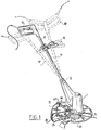
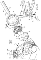
- housing 1 On the underside of housing 1 a motor shaft 3 protrudes downward, on which motor shaft is arranged a reel 4 for a trimming line 5.
- the trimming line 5 is wound onto the reel and protected in a reel housing 6, which housing is provided with a passage opening 7 for guiding through the active end part of line 5.
- Housing 6 is closed off on the underside by a press-in cover 9 which can support on the ground. By pressing in a cover 9, a determined length of line 5 is released each time and cut to length in order to enable cutting of the grass.
- the housing 1 is further provided with a handle 10 which is embodied with a shank 11 which is connected to a part of the housing 1 via a ball joint 12.
- a second handle 13 can be arranged halfway along the shank.
- the shank and handle 10, 11 can be set in various ways, which is further elucidated below.
- cover plate 15 On the side of housing 1 lying towards the handle 10 the active plane through which the line 5 is moved is protected on the top side by a cover plate 15.
- This cover plate serves as protection against grass, small stones, sand or wire portions being thrown around which can be dangerous for the user and his surroundings.
- the cover plate 15 only covers a sector angle of the complete circle around the bottom end of the housing, so that the wire remains fully visible on the side of the housing 1 remote from the user. This serves for observation of the work.
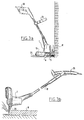
- the wire end part 5 can come too close to obstacles, as indicated in figure 3a by a wall M.
- the invention proposes arrangement of a bounding element 20.
- the bounding element 20 is embodied as a spoke wheel mounted concentrically round the motor shaft 3 on the underside of housing 1.
- Figure 2 shows that the spoke wheel can be slightly cup-shaped in order to place the peripheral edge 21 close to the active plane of the wire end 5.
- the bounding wheel 20 is freely rotatable so that, see figure 3a, housing 1 respectively reel housing 6 cannot come too close to the wall M.
- the wire end part 5 is therefore bent through a wider angle whereby wire breakage is avoided.
- the bounding element 20 is used as roller wheel, wherein the periphery 21, whether or not provided with a profile, rolls over the ground surface B. Due to the comparatively large wheel periphery, that is, the relatively large radius of curvature, operation of the device in this position is also considerably facilitated as support.
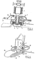
- the device In the position according to figure 3a, the device is supported by a carriage 25 on the underside of the cover plate 15.
- a special feature of this carriage 25 is that it extends from the edge of the cover plate in the direction of the rotation shaft 3 of the reel 4. The carriage 25 therefore leaves clear the cover 9 of reel housing 6 such that this remains freely accessible for replacing the reel and for regularly being able to supply new lengths of wire 5.
- FIG 4 an alternative embodiment of a carriage.
- This carriage consists of a supporting surface 26 which extends under reel 4 respectively reel housing 6 and which in the embodiment shown has a forked shape, consisting here of four parallel wire ends 27 which are mutually connected on the front side and continue in a wire 28, the end of which is mounted in two eyelets 29 on the front side of motor housing 1.
- the wire 28 is freely turnable in the eyelets 29 so that when the wire swivels to the left or right the wire ends 27 adjacent the reel housing 6 turn, whereby this left clear.
- This special support according to figure 4 can thus also swivel away when the device is used in the position according to figure 3b, that is, that bounding element 20 and the shape of the wheel can roll freely over the ground.
- the support of the device will however remain optimal when the device is moved forward by means of the handle 10 (not shown in figure 4), wherein the wire ends 27 exert a self-aligning action on the support owing to the eccentric mounting 29 of the support.
- the wire 28 of the support is curved such that it remains out of the active plane of the line 5.
- the support wire 28 can also be pushed and fixed into eyelets 29 in axial direction so that a height adjustment is easily realized.
- Figure 5 shows an alternative embodiment wherein the plate 15 at the rear is extended toward the front at 30, along the periphery of which a number of free-turning wheels 31 are mounted.
- the circle covered along the outside of wheels 31 forms a support surface that is movable relative to housing 1, so that a sufficient bounding is also obtained here to safeguard the line end 5, while the device can easily be moved forward over the field when it is used in the position according to figure 3b.
- Figure 6 shows a development of the embodiment according to figure 5 wherein the wheels 31' are suitable for guiding a belt 32 which is trained therearound.
- the belt serves for a uniform support of the device in the position according to figure 3b.
- the invention further relates to the handle 10 which is fixed to the shank 11.
- the shank 11 is accommodated via a universal joint 12 in the line of motor housing 1.
- the universal joint 12 makes it possible to rotate the shank 11 through 180° round the longitudinal axis thereof, for example into the position designated 10' in figure 1.
- the auxiliary handle 13 which is likewise fixed to shank 11 can therein also be rotated through 180° to obtain the correct adjustment for both the hands of the user.
- the universal joint 12 further enables a different angular position of shank 11 relative to housing 1, which is indicated by the positions 11' and 11''.
- shank with handles 10 and 13 can be placed into an optimal position relative to the housing, suitable for adjusting the device as comfortably as possible for the user in the various operational positions according to for instance figures 3a and 3b.
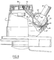
- This universal joint designated as a whole by 12, comprises a spherical chamber 40 connected to motor housing 1 and a spherical body 41 connected to shank 11.
- the periphery of the sphere 41 fits closely in the inside space of spherical chamber 40, which in figure 8 is formed by a spherically recessed portion 42 of the rear wall of housing 1, which is closed off on the top side by a semi-spherical cover 43.
- the latter is fixed by means of a groove 44 into which protrudes an edge of motor housing 1, which cover 43 has a slot-like opening 45 on the side facing the shank 11.
- the shank 11 can not only be placed into a position as according to figure 7 with full lines, but also into a position shown with broken lines, wherein the shank 11 can be adjusted as to angle relative to the motor shaft in motor housing 1 due to the slot-like opening 45 in cover 43.
- the ends of the slot-like openings serve as a stop to bound this rotation.
- the spherical body 41 In order to enable blocking of the height adjustment of the shank, it is recommended to embody the spherical body 41 with a number of straight grooves 46, which extend parallel to the centre line of the sphere perpendicular to the centre line of shank 11, wherein a part of the chamber wall 42 is interrupted, which interruption connects onto a guiding 47 for receiving a locking member 48 provided with straight ribs which co-act with the grooves 46 of the spherical body 41.
- the locking member 48 also see figure 9, is connected round the chamber 42 to a plate-like actuating member 49 which leads to the top of motor housing 1.
- a cap-like foot pedal 50 Arranged on motor housing 1 is a cap-like foot pedal 50 which is supported by protrusions 51 arranged on housing 1 around which pressure springs 52 are arranged.
- the pressure springs provide an upward directed force on the underside of the foot pedal 50.
- the latter is embodied with a ridge-like protrusion 53 which co-act
- the foot pedal 50 By exerting a downward force with the foot on the foot pedal 50, the foot pedal 50 is pressed downward counter to the action of springs 52 and plate-like element 49 is thus likewise pressed downward, which in turn presses the blocking member 48 down into guide 47.
- the ribs thereof come thereby to lie free of the ribs 46 on the spherical body, whereby the spherical body can be rotated relative to the spherical chamber.
- the springs 52 When foot pedal 50 is released the springs 52 will press it upward taking with it the plate 49 and the locking member 48 whereby the ribs 46, and thereby the spherical body 41, are locked in the then adjusted position.
- the spherical shape also enables rotation of shank 11 round its lengthwise axis, whereby the handle 10 can be turned through at least 180 degrees, also see figure 7. This rotation causes a second group of grooves 46' diametrically opposite the first group to come into engagement with the ribs of the locking member 48.
- the cover 43 rotates with the sphere 41 due to two flat surfaces 45' which lie against flat surfaces in cover 43, wherein a ridge 43' defines the end positions which preferably correspond with those as shown in figure 7, that is, that in the one end position handle 10 points downward relative to shank 11 and in the other end position upward, whereby the machine can be used in the operational position of figure 7, that is, the rotation shaft of the motor stands vertically, and in the operational position according to figure 3b wherein the rotation shaft of the motor is oriented horizontally.
- Figure 10 shows a detail of the bounding element 20, on the periphery of which is arranged a cutting member 60 in the form of a cutting blade.
- the cutting edge 61 is oriented such that, in the rotation direction of the wire 5, the end 5' thereof is cut off in order to bring wire 5 to the correct length relative to the axis of rotation.
- the cutting blade 60 can be pivoted relative to the spoke 62 of the wheel 20, on which two arms 64 of blade 60 are rotatable round 63.
- the knife blade 60 can thus be folded away from the position drawn with full lines in figure 10 to a position drawn with dashed lines so that the wire 5 can move through beneath knife blade 60.
- Shorter and longer wire ends can be realized by fixing knife-like cutting blades in other manner to for instance motor housing 1 respectively plate 15.
- FIG. 1 Shown for example in figure 1 is a knife blade 60 which is arranged on a bent arm 65 which is mounted in plate 15 for rotation at 66.
- a handle 67 is provided at the top end with which it is possible to turn knife blade 60 round the passage opening 66 and to thus place it under or outside the wheel-shaped bounding element 20.
- the wire can thereby be cut off shorter than the periphery of the wheel or longer than the periphery of the wheel or any intermediate length.
- a knife blade 60 is arranged on a pin 68 which is supported on the housing by eyelet-like supports 69.
- the pin 68, and thus the knife 60 can be moved up and downward by means of the knob 70 such that the knife can be carried from a position above wheel 20 to below wheel 20.
- the wire 5 can hereby be cut off at a desired short length.
- a reset spring 71 which acts on the pin 68 provides an automatic return of knife blade 60 above the wheel 20.
- a single elongate handle 35 is used, which is fixed about halfway along the shank 11.
- the handle On the side facing the machine housing the handle has a hammer-shaped end.
- This handle can also be placed into the desired position for use relative to the motor housing by means of the rotatable and pivotable shank 11.
- the advantage of this design is that the user is automatically forced to adjust the correct position, which enhances the work result.
Landscapes
- Life Sciences & Earth Sciences (AREA)
- Environmental Sciences (AREA)
- Harvester Elements (AREA)
Priority Applications (1)
| Application Number | Priority Date | Filing Date | Title |
|---|---|---|---|
| EP99204032A EP0976313A3 (fr) | 1992-12-23 | 1993-12-23 | Tondeuse à fil de coupe flexible |
Applications Claiming Priority (4)
| Application Number | Priority Date | Filing Date | Title |
|---|---|---|---|
| NL9202252A NL9202252A (nl) | 1992-12-23 | 1992-12-23 | Inrichting voor het trimmen van gewas. |
| NL9202252 | 1992-12-23 | ||
| NL9301416 | 1993-08-16 | ||
| NL9301416A NL9301416A (nl) | 1992-12-23 | 1993-08-16 | Inrichting voor het trimmen van gewas. |
Related Child Applications (1)
| Application Number | Title | Priority Date | Filing Date |
|---|---|---|---|
| EP99204032A Division EP0976313A3 (fr) | 1992-12-23 | 1993-12-23 | Tondeuse à fil de coupe flexible |
Publications (3)
| Publication Number | Publication Date |
|---|---|
| EP0603982A2 true EP0603982A2 (fr) | 1994-06-29 |
| EP0603982A3 EP0603982A3 (fr) | 1994-10-19 |
| EP0603982B1 EP0603982B1 (fr) | 2000-08-23 |
Family
ID=26647040
Family Applications (2)
| Application Number | Title | Priority Date | Filing Date |
|---|---|---|---|
| EP19930203656 Expired - Lifetime EP0603982B1 (fr) | 1992-12-23 | 1993-12-23 | Tondeuse à fil de coupe flexible |
| EP99204032A Withdrawn EP0976313A3 (fr) | 1992-12-23 | 1993-12-23 | Tondeuse à fil de coupe flexible |
Family Applications After (1)
| Application Number | Title | Priority Date | Filing Date |
|---|---|---|---|
| EP99204032A Withdrawn EP0976313A3 (fr) | 1992-12-23 | 1993-12-23 | Tondeuse à fil de coupe flexible |
Country Status (3)
| Country | Link |
|---|---|
| EP (2) | EP0603982B1 (fr) |
| DE (1) | DE69329270T2 (fr) |
| NL (1) | NL9301416A (fr) |
Cited By (7)
| Publication number | Priority date | Publication date | Assignee | Title |
|---|---|---|---|---|
| DE4437005C1 (de) * | 1994-10-15 | 1996-01-18 | Bernhardt Dr Med Hildebrandt | Wickelschutzvorrichtung für Motorsensen (Freischneider) mit Fadenschneidkopf |
| WO1996006523A1 (fr) * | 1994-08-30 | 1996-03-07 | Wolf-Geräte Gmbh Vertriebsges. Kg | Coupe-fil |
| WO1997031520A1 (fr) * | 1996-03-02 | 1997-09-04 | Wolf-Geräte Gmbh Vertriebsgesellschaft Kg | Coupe-bordure a joint articule |
| EP0893050A1 (fr) * | 1997-07-23 | 1999-01-27 | Mc Culloch North America, Inc. | Protecteur fil pour tondeuse à filament |
| WO1999005899A1 (fr) * | 1997-07-31 | 1999-02-11 | Coero Borga, Dario | Coupe-herbe pour la tonte manuelle de l'herbe et autre |
| EP1356722A1 (fr) * | 2002-04-26 | 2003-10-29 | Electrolux Outdoor Products | Tondeuse à filament |
| US10939614B2 (en) | 2017-11-03 | 2021-03-09 | Mtd Products Inc | Trimmer head |
Families Citing this family (10)
| Publication number | Priority date | Publication date | Assignee | Title |
|---|---|---|---|---|
| DE10248643B4 (de) * | 2002-10-18 | 2018-08-16 | Andreas Stihl Ag & Co. | Handgeführtes, tragbares Arbeitsgerät |
| GB2394879B (en) * | 2002-11-04 | 2005-11-23 | Electrolux Outdoor Prod Ltd | Trimmer |
| GB2394880B (en) * | 2002-11-04 | 2006-02-01 | Electrolux Outdoor Prod Ltd | Trimmer |
| US7100287B2 (en) * | 2003-06-10 | 2006-09-05 | Mccoid Trevor Albert | Trimmer lawn mowing device |
| DE10332918B4 (de) * | 2003-07-19 | 2007-02-01 | Wolf-Geräte AG | Gartengerät, insbesondere Fadenschneider |
| EP1746211A1 (fr) * | 2005-07-20 | 2007-01-24 | Meint Johannes Bouland | Carter de protection pour appareils de désherbage de joints |
| DE102005035024B4 (de) | 2005-07-27 | 2019-04-25 | Andreas Stihl Ag & Co. Kg | Schutzschild für einen Freischneider |
| US9179597B1 (en) * | 2013-04-04 | 2015-11-10 | Adrienne B. Kaspar | Lawnmower with telescoping handle |
| CN107094419A (zh) * | 2016-02-23 | 2017-08-29 | 苏州宝时得电动工具有限公司 | 打草机 |
| EP3927142B1 (fr) * | 2019-02-20 | 2023-06-21 | Husqvarna Ab | Outil de coupe portable |
Family Cites Families (12)
| Publication number | Priority date | Publication date | Assignee | Title |
|---|---|---|---|---|
| USRE21274E (en) * | 1939-11-21 | Electric cutter and trimmer | ||
| US2263431A (en) * | 1939-06-08 | 1941-11-18 | Leslie E White | Trimmer |
| US2702978A (en) * | 1949-06-20 | 1955-03-01 | Alvah W Fowler | Lawn mower and edger |
| US3872930A (en) * | 1973-03-13 | 1975-03-25 | Rouel R Campbell | Lawn edger |
| DE2448129A1 (de) * | 1974-10-09 | 1976-04-22 | Gerhard Dr Ing Maerz | Rasenmaeher mit schwenkbarem fuehrungsbuegel |
| EP0005540B1 (fr) * | 1978-05-24 | 1982-04-21 | Wolf-Geräte GmbH | Filin de coupe pour bordures de gazon |
| US4603478A (en) * | 1984-08-13 | 1986-08-05 | Allegretti & Company | Trimmer with adjustable handle |
| DE3506717A1 (de) * | 1985-02-26 | 1986-08-28 | Artur 7266 Neuweiler Mast | Schutzvorrichtung fuer motorsensen |
| ZA858369B (en) * | 1985-10-31 | 1986-07-30 | Middleton J T & Co Pty Ltd | Wheeled line trimmer |
| US5020281A (en) * | 1989-04-03 | 1991-06-04 | American Pneumatic Technologies, Inc. | High speed rotary hand tool with adjustable head coupling |
| US5060383A (en) * | 1990-08-06 | 1991-10-29 | Ratkiewich Richard H | Vegetation cutter |
| US5115870A (en) * | 1990-12-31 | 1992-05-26 | Byrne Steven E | Flexible flail trimmer with combined guide and guard |
-
1993
- 1993-08-16 NL NL9301416A patent/NL9301416A/nl not_active Application Discontinuation
- 1993-12-23 EP EP19930203656 patent/EP0603982B1/fr not_active Expired - Lifetime
- 1993-12-23 EP EP99204032A patent/EP0976313A3/fr not_active Withdrawn
- 1993-12-23 DE DE1993629270 patent/DE69329270T2/de not_active Expired - Fee Related
Cited By (9)
| Publication number | Priority date | Publication date | Assignee | Title |
|---|---|---|---|---|
| WO1996006523A1 (fr) * | 1994-08-30 | 1996-03-07 | Wolf-Geräte Gmbh Vertriebsges. Kg | Coupe-fil |
| DE4437005C1 (de) * | 1994-10-15 | 1996-01-18 | Bernhardt Dr Med Hildebrandt | Wickelschutzvorrichtung für Motorsensen (Freischneider) mit Fadenschneidkopf |
| WO1997031520A1 (fr) * | 1996-03-02 | 1997-09-04 | Wolf-Geräte Gmbh Vertriebsgesellschaft Kg | Coupe-bordure a joint articule |
| EP0893050A1 (fr) * | 1997-07-23 | 1999-01-27 | Mc Culloch North America, Inc. | Protecteur fil pour tondeuse à filament |
| WO1999005899A1 (fr) * | 1997-07-31 | 1999-02-11 | Coero Borga, Dario | Coupe-herbe pour la tonte manuelle de l'herbe et autre |
| US6381854B1 (en) | 1997-07-31 | 2002-05-07 | Dario Coero Borga | Bush-cutter for the manual mowing of grass and the like |
| EP1356722A1 (fr) * | 2002-04-26 | 2003-10-29 | Electrolux Outdoor Products | Tondeuse à filament |
| GB2387760B (en) * | 2002-04-26 | 2005-06-22 | Electrolux Outdoor Prod Ltd | Trimmer |
| US10939614B2 (en) | 2017-11-03 | 2021-03-09 | Mtd Products Inc | Trimmer head |
Also Published As
| Publication number | Publication date |
|---|---|
| EP0603982B1 (fr) | 2000-08-23 |
| EP0976313A3 (fr) | 2000-03-01 |
| DE69329270T2 (de) | 2001-03-29 |
| DE69329270D1 (de) | 2000-09-28 |
| EP0976313A2 (fr) | 2000-02-02 |
| EP0603982A3 (fr) | 1994-10-19 |
| NL9301416A (nl) | 1994-07-18 |
Similar Documents
| Publication | Publication Date | Title |
|---|---|---|
| EP0603982A2 (fr) | Tondeuse à fil de coupe flexible | |
| US5661960A (en) | Power tool arm engaging assembly and wheeled platform for a line trimmer | |
| US10244678B2 (en) | Blade guard for a robot lawnmower | |
| US7131499B2 (en) | Combination line trimmer and edger | |
| US6260278B1 (en) | Hand-held lawn and brush trimmer having manual trimmer head adjustment mechanisms | |
| US4949536A (en) | Lawn and garden trimmer apparatus | |
| US4829755A (en) | Trimmer wheels | |
| US5560189A (en) | Edging and trimming lawn mower assembly | |
| US5477665A (en) | Support strut assembly for rotating flexible line-type vegetation trimmer | |
| EP3549429B1 (fr) | Robot de tondeuse à gazon | |
| EP1020257B1 (fr) | Manche de tondeuse | |
| EP1435194B1 (fr) | Tondeuse à filament | |
| US5287683A (en) | Sweep cut trimmer mower and converting platform | |
| US6971223B2 (en) | Wheeled trimmer device of adjustable height | |
| US6997268B2 (en) | Trimmer | |
| CA2132998A1 (fr) | Appareils servant a tailler des vegetaux | |
| US3805385A (en) | Housing for a portable grass shear | |
| GB2026928A (en) | Flail-type cutter with adjustable handle and handgrip | |
| CN1732736B (zh) | 花园工具调节装置 | |
| US3861127A (en) | Housing for a portable grass shear | |
| US3126968A (en) | Lawn edger | |
| EP0222515A1 (fr) | Tondeuse à fil avec roues | |
| AU2020100005A4 (en) | Line trimmer assembly | |
| CN110337888B (zh) | 一种切割直径可调的打草机 | |
| AU2021200001A1 (en) | Line trimmer assembly |
Legal Events
| Date | Code | Title | Description |
|---|---|---|---|
| PUAI | Public reference made under article 153(3) epc to a published international application that has entered the european phase |
Free format text: ORIGINAL CODE: 0009012 |
|
| AK | Designated contracting states |
Kind code of ref document: A2 Designated state(s): DE FR GB NL SE |
|
| PUAL | Search report despatched |
Free format text: ORIGINAL CODE: 0009013 |
|
| AK | Designated contracting states |
Kind code of ref document: A3 Designated state(s): DE FR GB NL SE |
|
| 17P | Request for examination filed |
Effective date: 19950331 |
|
| 17Q | First examination report despatched |
Effective date: 19970226 |
|
| GRAG | Despatch of communication of intention to grant |
Free format text: ORIGINAL CODE: EPIDOS AGRA |
|
| GRAG | Despatch of communication of intention to grant |
Free format text: ORIGINAL CODE: EPIDOS AGRA |
|
| GRAH | Despatch of communication of intention to grant a patent |
Free format text: ORIGINAL CODE: EPIDOS IGRA |
|
| GRAG | Despatch of communication of intention to grant |
Free format text: ORIGINAL CODE: EPIDOS AGRA |
|
| GRAH | Despatch of communication of intention to grant a patent |
Free format text: ORIGINAL CODE: EPIDOS IGRA |
|
| GRAH | Despatch of communication of intention to grant a patent |
Free format text: ORIGINAL CODE: EPIDOS IGRA |
|
| GRAA | (expected) grant |
Free format text: ORIGINAL CODE: 0009210 |
|
| AK | Designated contracting states |
Kind code of ref document: B1 Designated state(s): DE FR GB NL SE |
|
| PG25 | Lapsed in a contracting state [announced via postgrant information from national office to epo] |
Ref country code: NL Free format text: LAPSE BECAUSE OF FAILURE TO SUBMIT A TRANSLATION OF THE DESCRIPTION OR TO PAY THE FEE WITHIN THE PRESCRIBED TIME-LIMIT Effective date: 20000823 |
|
| REF | Corresponds to: |
Ref document number: 69329270 Country of ref document: DE Date of ref document: 20000928 |
|
| ET | Fr: translation filed | ||
| PG25 | Lapsed in a contracting state [announced via postgrant information from national office to epo] |
Ref country code: SE Free format text: LAPSE BECAUSE OF FAILURE TO SUBMIT A TRANSLATION OF THE DESCRIPTION OR TO PAY THE FEE WITHIN THE PRESCRIBED TIME-LIMIT Effective date: 20001123 |
|
| NLV1 | Nl: lapsed or annulled due to failure to fulfill the requirements of art. 29p and 29m of the patents act | ||
| PLBE | No opposition filed within time limit |
Free format text: ORIGINAL CODE: 0009261 |
|
| 26N | No opposition filed | ||
| PGFP | Annual fee paid to national office [announced via postgrant information from national office to epo] |
Ref country code: GB Payment date: 20011203 Year of fee payment: 9 |
|
| PGFP | Annual fee paid to national office [announced via postgrant information from national office to epo] |
Ref country code: FR Payment date: 20011228 Year of fee payment: 9 |
|
| REG | Reference to a national code |
Ref country code: GB Ref legal event code: IF02 |
|
| PGFP | Annual fee paid to national office [announced via postgrant information from national office to epo] |
Ref country code: DE Payment date: 20020131 Year of fee payment: 9 |
|
| PG25 | Lapsed in a contracting state [announced via postgrant information from national office to epo] |
Ref country code: GB Free format text: LAPSE BECAUSE OF NON-PAYMENT OF DUE FEES Effective date: 20021223 |
|
| PG25 | Lapsed in a contracting state [announced via postgrant information from national office to epo] |
Ref country code: DE Free format text: LAPSE BECAUSE OF NON-PAYMENT OF DUE FEES Effective date: 20030701 |
|
| GBPC | Gb: european patent ceased through non-payment of renewal fee |
Effective date: 20021223 |
|
| PG25 | Lapsed in a contracting state [announced via postgrant information from national office to epo] |
Ref country code: FR Free format text: LAPSE BECAUSE OF NON-PAYMENT OF DUE FEES Effective date: 20030901 |
|
| REG | Reference to a national code |
Ref country code: FR Ref legal event code: ST |