EP0604012A1 - Elektrochemischer Gassensor - Google Patents
Elektrochemischer Gassensor Download PDFInfo
- Publication number
- EP0604012A1 EP0604012A1 EP93309031A EP93309031A EP0604012A1 EP 0604012 A1 EP0604012 A1 EP 0604012A1 EP 93309031 A EP93309031 A EP 93309031A EP 93309031 A EP93309031 A EP 93309031A EP 0604012 A1 EP0604012 A1 EP 0604012A1
- Authority
- EP
- European Patent Office
- Prior art keywords
- porous
- electrode
- block
- reservoir
- sensor
- Prior art date
- Legal status (The legal status is an assumption and is not a legal conclusion. Google has not performed a legal analysis and makes no representation as to the accuracy of the status listed.)
- Withdrawn
Links
Images
Classifications
-
- G—PHYSICS
- G01—MEASURING; TESTING
- G01N—INVESTIGATING OR ANALYSING MATERIALS BY DETERMINING THEIR CHEMICAL OR PHYSICAL PROPERTIES
- G01N27/00—Investigating or analysing materials by the use of electric, electrochemical, or magnetic means
- G01N27/26—Investigating or analysing materials by the use of electric, electrochemical, or magnetic means by investigating electrochemical variables; by using electrolysis or electrophoresis
- G01N27/403—Cells and electrode assemblies
- G01N27/404—Cells with anode, cathode and cell electrolyte on the same side of a permeable membrane which separates them from the sample fluid, e.g. Clark-type oxygen sensors
- G01N27/4045—Cells with anode, cathode and cell electrolyte on the same side of a permeable membrane which separates them from the sample fluid, e.g. Clark-type oxygen sensors for gases other than oxygen
Definitions
- the invention relates to electrochemical gas sensors of the kind comprising sensing and counter electrodes, means for permitting access of gas to the sensing electrode; an electrolyte reservoir; and means for conveying electrolyte to the sensing and counter electrodes.
- electrochemical gas sensors are hereinafter referred to as of the kind described.
- an electrochemical gas sensor of the kind described is shown in GB-A-2094005.
- the reservoir is provided in a hollowed out bottom plate which has a covering flange which supports the various components of the sensor including the sensing and counter electrodes and, where provided, a reference electrode.
- Electrolyte passes through a small aperture in the covering flange in a wick extending into the reservoir and extending through apertures in some of the components and into contact with hydrophylic separators to convey electrolyte to the region between the sensing and counter electrodes.
- the use of a wick is undesirable due to the complex manufacturing techniques required to thread the wick through the various components.
- the arrangement requires an additional rear vent which provides a possible source of leakage as well as leading to a more complex construction.
- an electrochemical gas sensor of the kind described is characterised in that the conveying means includes a porous, block-like body positioned in the reservoir and at least partly supporting other components of the sensor.
- the term "block-like” is intended to mean any 3-dimensional shape which provides a supporting surface for the other sensor components.
- the reservoir includes a porous, block-like body which not only provides the conveying means but also at least partly supports other components such as electrodes, separators and the like of the sensor.
- the porous, block-like body only partly fills the reservoir.
- the block-like body preferably has a substantially square cross-section while the reservoir has a substantially circular cross-section.
- the porous, block-like body is at least partially hydrophobic. This is particularly advantageous during assembly of a sensor since the sensor can be assembled by first supplying electrolyte to the reservoir; placing the porous, block-like body in the reservoir (and electrolyte); assembling the remaining components and sealing the resulting assembly. Thereafter, the assembly can be inverted to cause the electrolyte to wet through to the sensing and counter electrodes. This should be contrasted with the conventional method which requires that the components are assembled in dry form, the assembly sealed, and then electrolyte supplied through a side opening which has to be subsequently plugged and sealed.
- the porous, block-like body can be electrically conducting or non-conducting and could be constituted, for example by VYON, a porous, high density, polyethylene made by Porvair plc of Kings Lynn, Norfolk, England. VYON is also partially hydrophobic.
- the body is electrically conductive and electrochemically active since in that case the body can also form the counter-electrode. This simplifies still further the construction of the device. This is particularly useful where the reaction involved is either oxygen reduction or evolution, ie. where the sensing electrode reaction is either anodic oxidation (as in a CO sensor) or a cathodic reduction (as in a chlorine sensor) respectively.
- an additional, counter-electrode member can be arranged to contact the electrically conducting and electrochemically active body.
- the body then acts as both a current collector aid (although a separate current collector would also be necessary) and as an additional surface for the counter electrode reaction.
- active electro-catalyst for example Pt-black
- VYON pores of the body
- RVC Reticulated Vitreous Carbon
- This material is manufactured by The Electrosynthesis Co Inc., P.O.Box 16, East Amhurst, N.Y.14051, U.S.A.
- RVC is an open pore "foam" material composed solely of vitreous carbon which is a glass-like carbon combining some of the properties of glass with some of those of normal industrial carbons.
- RVC has an exceptionally high void volume (97%), high surface area combined with self-supporting rigidity, low resistance to fluid flow, electrical conductivity, and electro-chemical activity. Furthermore, it has exceptional chemical inertness over a wide temperature range, being particularly compatible with strong mineral acid electrolytes. It is very light (low density) and easily formed and handled into the desired shapes for these applications.
- an electro-catalytic gas electrode includes an electrically conductive and electrochemically active porous member whose pores are impregnated with an electrocatalyst.
- This new electrode should be contrasted with conventional electrodes of pressed catalyst/PTFE mixtures directly onto porous PTFE tape, with the metal foil current collectors providing a simple pressure contact of the catalyst layer.
- the new electrode is particularly useful in an electrochemical gas sensor in that it enables one member of the sensor construction, namely the reference or counter electrode, to be eliminated.
- the electrode is made from RVC.
- the electrode could comprise a reference electrode or a counter electrode.
- a sensing electrode 1 comprises porous PTFE tape to which is bonded a catalyst/PTFE mixture, the latter covering an area of smaller diameter than the tape.
- a counter electrode 2 is of similar construction but with a hole 3 through which a wick 4 passes to an electrolyte reservoir/expansion chamber 5.
- Strip-like current collectors 6, 7 contact the sensing and counter electrodes respectively (see also Figure 2) and lead out to terminal posts 8 (one only shown).
- the wick 4 extends from a separator 9 which with a further separator 10 and an annular gasket 11, which gasket may conveniently be cut from porous PTFE tape, makes up an interior sandwich between the electrodes.
- the sensing electrode 1 Above the sensing electrode 1 is an O-ring 12 with a rigid retaining ring 13 of smaller height than the O-ring, the underside of which has slots (not shown) to allow egress of the current collectors 6 and 7.
- a top plate 14 carries capillary holes 15 which form a diffusion barrier for restricting access of the gas to be detected and has a cavity 16 to allow for diffusion across the sensing electrode.
- a bottom plate 17 carries the electrolyte reservoir/expansion chamber 5.
- the wick 4 passes through a hole 18 therein, and is arranged to make good contact with wick extension 4a which extends around the perimeter of chamber 5 to ensure contact with the electrolyte in all sensor attitudes.
- the reservoir is closed by a cover plate 20. It will be noted that the wick is necessary since the floor of the base plate supports the electrode stack and electrolyte must therefore wick through the small hole 18 in the centre of the base plate.
- the whole is sealed or clamped together, for example with bolts and nuts (not shown) through the top and bottom plates 14 and 17, ultrasonic welding, thermal welding, or crimp methods.
- the O-ring is thereby compressed.
- the outer annular portions of the PTFE tape in the electrodes 1 and 2, not covered with catalyst, are thus brought into intimate compressive contact with the PTFE gasket 11.
- electrolyte may now be introduced to partially fill the reservoir 5 via a side aperture (not shown) in bottom plate 17 which is then plugged using a plastic plug and suitable cement.
- the electrolyte wets up the separators 9 and 10 via the wick 4 to form the electrolyte connection between the electrodes.
- the amount of electrolyte is chosen to only partially fill the reservoir/expansion chamber 5 and so that volume changes resulting from gain or loss of water vapour during the operation of the sensor may be accommodated.
- An air vent (not shown) is provided in a cover plate 20 to accommodate expansion/contraction within the reservoir 5.
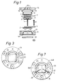
- FIG. 2 is a view similar to Figure 1 but showing an example of a gas sensor according to the invention.
- items corresponding to items shown in Figure 1 have been given the same reference numerals. In this case, however, the sensor is a three electrode sensor rather than a two electrode sensor.
- the base plate 22 has a reservoir or well 23 opening upwardly and facing towards the electrodes.
- a plug of RVC or Vyon material 24 having a substantially square cross section ( Figure 3) sits in the reservoir 23 with a top surface substantially flush with a widened bore 25 in the base plate 22.
- a PTFE tape floor seal 26 Supported above the plug 24 and partially by the plug and partially by the floor of the widened bore 25 are positioned a PTFE tape floor seal 26, the current collector 6 and counter electrode 2, a separator 27 of hydrophylic material, a current collector 28, a reference electrode 29, the separator 10, the current collector 7 and the sensing electrode 1.
- the components are held in place as before by sealing the top plate 14 onto the base plate 22, the various components being urged into contact by the O-ring 12.
- the separator 27 When assembled, the separator 27 will contact the plug 24 through an aperture 30 in the counter electrode 2 and electrolyte can pass from the plug 24 through the separator 27 into the region of the reference electrode 29 and through the separator 10 into the region of the sensing electrode 1.
- electrolyte is supplied to the reservoir 23 following which the plug 24 is positioned in the reservoir.
- the remaining components shown in Figure 2 are then assembled with the base plate 22 and are sealed together using any of the methods mentioned above.
- the assembled device is inverted to allow electrolyte to wet via the plug 24 through the separators.
- the counter electrode 2 and the floor seal 26 are very thin so that electrolyte will pass easily through from the plug 24 to the separator 27 without the need for a wick.
- electrolyte is supplied to the reservoir 23 at the beginning of the assembly operation.
- the electrodes 1, 29, 2 shown in Figure 2 can be constructed in a conventional manner. However, the electrodes could also be formed from the RVC material as described above.
- the electrodes shown in Figure 2 be made of the RVC material, but the RVC block itself can be used to constitute one or both of the reference and counter electrodes.
- RVC is electrically conducting and electrochemically active.
- it can support the oxygen reduction reaction. Consequently, it can be used as a combined wick and electrode with the result that the counter electrode 2 can be omitted as a separate item and incorporated into the plug 24.
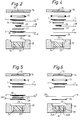
- Figure 4 illustrates an example in which the RVC block 24 constitutes the counter electrode.
- the floor seal 26 is sufficiently thin for the current collector 6 to make electrical contact with the block 24.
- the Vyon or RVC plug can be arranged to provide extra catalytic activity if its pores are impregnated with catalyst such as silver, gold, platinum or chemically modified materials as used in bioelectrochemical or enzyme electrodes.
- catalyst such as silver, gold, platinum or chemically modified materials as used in bioelectrochemical or enzyme electrodes.
- active electrode materials could be incorporated into the structure to provide an alternative counter or reference electrode action, eg. Ag/AgCl, Ag/Ag20, Pb02 as examples of cathode active materials or metals such as lead or zinc as examples of anode active materials.
- FIG 5 illustrates an example in which the RVC block 24 constitutes the reference electrode.
- the current collector 28 has been moved to just above the floor seal 26 so that it will make electrical contact with the plug 24 and the separator 27 has been moved between the current collectors 6, 28.
- the RVC block 24 could provide both the counter and reference electrodes. In some cases, these may be positioned one above the other but in the preferred arrangement, as shown in Figures 6 and 7, the RVC block is divided into two portions 24A, 24B which are electrically isolated by an insulator 30. As can be seen most clearly in Figure 7, the current collectors 6, 28 extend at about 120° to each other over their respective portions of the block 24B, 24A which they will electrically engage when the sensor is assembled.
Landscapes
- Chemical & Material Sciences (AREA)
- Life Sciences & Earth Sciences (AREA)
- Health & Medical Sciences (AREA)
- Physics & Mathematics (AREA)
- Chemical Kinetics & Catalysis (AREA)
- Electrochemistry (AREA)
- Molecular Biology (AREA)
- Analytical Chemistry (AREA)
- Biochemistry (AREA)
- General Health & Medical Sciences (AREA)
- General Physics & Mathematics (AREA)
- Immunology (AREA)
- Pathology (AREA)
- Measuring Oxygen Concentration In Cells (AREA)
- Hybrid Cells (AREA)
Applications Claiming Priority (2)
| Application Number | Priority Date | Filing Date | Title |
|---|---|---|---|
| GB929226937A GB9226937D0 (en) | 1992-12-24 | 1992-12-24 | Electrochemical gas sensor |
| GB9226937 | 1992-12-24 |
Publications (1)
| Publication Number | Publication Date |
|---|---|
| EP0604012A1 true EP0604012A1 (de) | 1994-06-29 |
Family
ID=10727206
Family Applications (1)
| Application Number | Title | Priority Date | Filing Date |
|---|---|---|---|
| EP93309031A Withdrawn EP0604012A1 (de) | 1992-12-24 | 1993-11-11 | Elektrochemischer Gassensor |
Country Status (5)
| Country | Link |
|---|---|
| US (1) | US5395507A (de) |
| EP (1) | EP0604012A1 (de) |
| JP (1) | JPH06229974A (de) |
| CA (1) | CA2109547A1 (de) |
| GB (1) | GB9226937D0 (de) |
Cited By (7)
| Publication number | Priority date | Publication date | Assignee | Title |
|---|---|---|---|---|
| EP0763730A1 (de) * | 1995-08-29 | 1997-03-19 | City Technology Limited | Elektrochemische Gassensoranordnung |
| EP0780686A1 (de) | 1995-12-20 | 1997-06-25 | City Technology Limited | Elektrochemischer Gassensor |
| EP1179731A3 (de) * | 2000-08-01 | 2002-03-06 | Riken Keiki Co., Ltd. | Galvanischer Gassensor mit einer Sauerstoff reduzierenden Gegenelektrode |
| EP1332358A4 (de) * | 2000-10-13 | 2005-10-05 | Mst Technology Gmbh | Säuregasmesssensoren und verfahren zu ihrer herstellung |
| DE19681487B3 (de) * | 1995-04-21 | 2011-11-10 | Mine Safety Appliances Co. | Elektrochemischer Sensor zum Aufspüren von Stickstoffdioxid |
| EP2503327A1 (de) * | 2011-03-25 | 2012-09-26 | Life Safety Distribution AG | Gasdetektor mit zweipoliger Gegen-/Referenzelektrode |
| WO2013140140A2 (en) | 2012-03-20 | 2013-09-26 | Isis Innovation Ltd | Electrochemical temperature measurement |
Families Citing this family (20)
| Publication number | Priority date | Publication date | Assignee | Title |
|---|---|---|---|---|
| DE4401570A1 (de) * | 1994-01-20 | 1995-07-27 | Rwe Energie Ag | Einrichtung für die Messung von Zustandsgrößen in Gasen mit zumindest einem Halbleiter-Gassensor |
| US5830337A (en) * | 1996-07-24 | 1998-11-03 | Gastech, Inc. | Electrochemical gas sensor |
| CA2245050C (en) * | 1997-09-11 | 2000-09-05 | Kehoe Component Sales Inc. Dba Pace Electronic Products Inc. | Three-electrode electrochemical gas sensor |
| US5988232A (en) * | 1998-08-14 | 1999-11-23 | Tokheim Corporation | Vapor recovery system employing oxygen detection |
| CA2255472C (en) * | 1998-12-10 | 2005-02-22 | Senco Sensors Inc. | Electrochemical gas sensor with gas communication means |
| US6176989B1 (en) * | 1998-12-28 | 2001-01-23 | Teledyne Technologies Incorp. | Electrochemical gas sensor |
| US6524740B1 (en) * | 2000-03-21 | 2003-02-25 | Teledyne Technologies Incorporated | Method and apparatus for improved gas sensor |
| JP2002055077A (ja) * | 2000-08-11 | 2002-02-20 | Riken Keiki Co Ltd | ガルバニ電池式ガスセンサー |
| GB0027877D0 (en) * | 2000-11-15 | 2000-12-27 | Alphasense Ltd | Electrochemical gas sensor |
| DE10103701C1 (de) * | 2001-01-26 | 2002-09-12 | Heraeus Electro Nite Int | Messeinrichtung zur Bestimmung der Sauerstoffaktivität in Metallschmelzen oder Schlackeschmelzen |
| DE10208074C1 (de) * | 2002-02-25 | 2003-09-25 | Draegerwerk Ag | Elektrochemischer Gassensor mit nicht planarer Diffusionsmembran und Elektrodenanordnung |
| US6666963B1 (en) * | 2002-08-14 | 2003-12-23 | Industrial Scientific Corporation | Oxygen sensor |
| US7664607B2 (en) | 2005-10-04 | 2010-02-16 | Teledyne Technologies Incorporated | Pre-calibrated gas sensor |
| DE102007004147A1 (de) * | 2007-01-22 | 2008-07-24 | Heraeus Electro-Nite International N.V. | Verfahren zum Beeinflussen der Eigenschaften von Gusseisen sowie Sauerstoffsensor |
| US7656236B2 (en) * | 2007-05-15 | 2010-02-02 | Teledyne Wireless, Llc | Noise canceling technique for frequency synthesizer |
| US8179045B2 (en) * | 2008-04-22 | 2012-05-15 | Teledyne Wireless, Llc | Slow wave structure having offset projections comprised of a metal-dielectric composite stack |
| CN102353708B (zh) * | 2011-09-23 | 2013-06-26 | 中国科学院海洋研究所 | 一种可拆卸电极 |
| US9202660B2 (en) | 2013-03-13 | 2015-12-01 | Teledyne Wireless, Llc | Asymmetrical slow wave structures to eliminate backward wave oscillations in wideband traveling wave tubes |
| US10468697B2 (en) | 2013-07-26 | 2019-11-05 | Alcotek, Inc. | Alcohol detecting fuel cell |
| CA2915262A1 (en) | 2013-07-26 | 2015-01-29 | Alcotek, Inc. | Method of compressing fuel cell electrodes, resultant fuel cell, and a housing for the fuel cell which utilizes electrolyte reservoirs |
Citations (4)
| Publication number | Priority date | Publication date | Assignee | Title |
|---|---|---|---|---|
| US3992267A (en) * | 1973-10-02 | 1976-11-16 | Energetics Science, Inc. | Electrochemical gas detection method |
| US4118194A (en) * | 1977-04-08 | 1978-10-03 | Rockwell International Corporation | Sensor for fluid components |
| US4221651A (en) * | 1979-06-25 | 1980-09-09 | Rockwell International Corporation | Electrochemical cell for measuring hydrogen in metal |
| US5173166A (en) * | 1990-04-16 | 1992-12-22 | Minitech Co. | Electrochemical gas sensor cells |
Family Cites Families (2)
| Publication number | Priority date | Publication date | Assignee | Title |
|---|---|---|---|---|
| GB2094005B (en) * | 1981-02-03 | 1985-05-30 | Coal Industry Patents Ltd | Electrochemical gas sensor |
| US5242765A (en) * | 1992-06-23 | 1993-09-07 | Luz Electric Fuel Israel Limited | Gas diffusion electrodes |
-
1992
- 1992-12-24 GB GB929226937A patent/GB9226937D0/en active Pending
-
1993
- 1993-11-11 EP EP93309031A patent/EP0604012A1/de not_active Withdrawn
- 1993-11-17 US US08/154,136 patent/US5395507A/en not_active Expired - Fee Related
- 1993-11-18 CA CA002109547A patent/CA2109547A1/en not_active Abandoned
- 1993-12-24 JP JP5345899A patent/JPH06229974A/ja not_active Withdrawn
Patent Citations (4)
| Publication number | Priority date | Publication date | Assignee | Title |
|---|---|---|---|---|
| US3992267A (en) * | 1973-10-02 | 1976-11-16 | Energetics Science, Inc. | Electrochemical gas detection method |
| US4118194A (en) * | 1977-04-08 | 1978-10-03 | Rockwell International Corporation | Sensor for fluid components |
| US4221651A (en) * | 1979-06-25 | 1980-09-09 | Rockwell International Corporation | Electrochemical cell for measuring hydrogen in metal |
| US5173166A (en) * | 1990-04-16 | 1992-12-22 | Minitech Co. | Electrochemical gas sensor cells |
Cited By (9)
| Publication number | Priority date | Publication date | Assignee | Title |
|---|---|---|---|---|
| DE19681487B3 (de) * | 1995-04-21 | 2011-11-10 | Mine Safety Appliances Co. | Elektrochemischer Sensor zum Aufspüren von Stickstoffdioxid |
| EP0763730A1 (de) * | 1995-08-29 | 1997-03-19 | City Technology Limited | Elektrochemische Gassensoranordnung |
| US5632875A (en) * | 1995-08-29 | 1997-05-27 | City Technology Limited | Electrochemical gas sensor assembly |
| EP1512968A1 (de) | 1995-08-29 | 2005-03-09 | City Technology Limited | Elektrochemische Gassensoranordnung |
| EP0780686A1 (de) | 1995-12-20 | 1997-06-25 | City Technology Limited | Elektrochemischer Gassensor |
| EP1179731A3 (de) * | 2000-08-01 | 2002-03-06 | Riken Keiki Co., Ltd. | Galvanischer Gassensor mit einer Sauerstoff reduzierenden Gegenelektrode |
| EP1332358A4 (de) * | 2000-10-13 | 2005-10-05 | Mst Technology Gmbh | Säuregasmesssensoren und verfahren zu ihrer herstellung |
| EP2503327A1 (de) * | 2011-03-25 | 2012-09-26 | Life Safety Distribution AG | Gasdetektor mit zweipoliger Gegen-/Referenzelektrode |
| WO2013140140A2 (en) | 2012-03-20 | 2013-09-26 | Isis Innovation Ltd | Electrochemical temperature measurement |
Also Published As
| Publication number | Publication date |
|---|---|
| GB9226937D0 (en) | 1993-02-17 |
| JPH06229974A (ja) | 1994-08-19 |
| US5395507A (en) | 1995-03-07 |
| CA2109547A1 (en) | 1994-06-25 |
Similar Documents
| Publication | Publication Date | Title |
|---|---|---|
| US5395507A (en) | Electrochemical gas sensor | |
| US6454923B1 (en) | Gas sensor | |
| RU2147120C1 (ru) | Газовый датчик | |
| US4769122A (en) | Compact electrochemical cell for gas detection | |
| US5830337A (en) | Electrochemical gas sensor | |
| EP0886776B1 (de) | Elektrochemischer sensor | |
| US20020121438A1 (en) | Electrochemical gas sensor | |
| US6666963B1 (en) | Oxygen sensor | |
| KR100739918B1 (ko) | 전기화학적 가스 센서 | |
| US5336390A (en) | Electrochemical gas sensor with disk-shaped electrodes, which are also electrical contact leads | |
| US5547554A (en) | Electrochemical measuring cell having a gas-permeable housing | |
| EP0055269A1 (de) | Elektrochemischer gasfühler, elektroden dafür und verfahren zur herstellung solcher fühler und elektroden | |
| CN1193231C (zh) | 溶于流体中的乙炔浓度的检测与测量设备 | |
| EP2494345B1 (de) | Sensor mit belüftungselement | |
| US8496795B2 (en) | Electrochemical gas sensor with at least one punctiform measuring electrode | |
| GB2178540A (en) | Electrochemical gas sensor | |
| CA1226899A (en) | Electrochemical measuring cell | |
| GB2386690A (en) | An electrochemical gas sensor | |
| JP4463145B2 (ja) | 電気化学ガスセンサとその製造方法 | |
| JPH05240929A (ja) | 電気化学的特性評価装置 | |
| US20050178186A1 (en) | Gas sensor | |
| US20230204535A1 (en) | Gas sensor element and gas sensor | |
| JP2003207483A (ja) | ガスセンサ | |
| KR910006715A (ko) | 전기 화학 가스 센서 |
Legal Events
| Date | Code | Title | Description |
|---|---|---|---|
| PUAI | Public reference made under article 153(3) epc to a published international application that has entered the european phase |
Free format text: ORIGINAL CODE: 0009012 |
|
| AK | Designated contracting states |
Kind code of ref document: A1 Designated state(s): DE FR GB IT |
|
| 17P | Request for examination filed |
Effective date: 19941223 |
|
| 18W | Application withdrawn |
Withdrawal date: 19960809 |