EP0604052A2 - Une méthode et un système pour situer des objets avec une précision inférieure au pixel - Google Patents
Une méthode et un système pour situer des objets avec une précision inférieure au pixel Download PDFInfo
- Publication number
- EP0604052A2 EP0604052A2 EP93309753A EP93309753A EP0604052A2 EP 0604052 A2 EP0604052 A2 EP 0604052A2 EP 93309753 A EP93309753 A EP 93309753A EP 93309753 A EP93309753 A EP 93309753A EP 0604052 A2 EP0604052 A2 EP 0604052A2
- Authority
- EP
- European Patent Office
- Prior art keywords
- fiducial
- block
- edge
- image elements
- sampling window
- Prior art date
- Legal status (The legal status is an assumption and is not a legal conclusion. Google has not performed a legal analysis and makes no representation as to the accuracy of the status listed.)
- Granted
Links
Images


Classifications
-
- G—PHYSICS
- G06—COMPUTING OR CALCULATING; COUNTING
- G06T—IMAGE DATA PROCESSING OR GENERATION, IN GENERAL
- G06T7/00—Image analysis
- G06T7/70—Determining position or orientation of objects or cameras
-
- G—PHYSICS
- G06—COMPUTING OR CALCULATING; COUNTING
- G06T—IMAGE DATA PROCESSING OR GENERATION, IN GENERAL
- G06T2207/00—Indexing scheme for image analysis or image enhancement
- G06T2207/30—Subject of image; Context of image processing
- G06T2207/30108—Industrial image inspection
- G06T2207/30148—Semiconductor; IC; Wafer
-
- G—PHYSICS
- G06—COMPUTING OR CALCULATING; COUNTING
- G06V—IMAGE OR VIDEO RECOGNITION OR UNDERSTANDING
- G06V10/00—Arrangements for image or video recognition or understanding
- G06V10/20—Image preprocessing
- G06V10/24—Aligning, centring, orientation detection or correction of the image
- G06V10/245—Aligning, centring, orientation detection or correction of the image by locating a pattern; Special marks for positioning
Definitions
- the invention relates to automated guidance systems in general, and more particularly, to methods and systems for precisely locating an/or aligning objects.
- Automated manufacturing systems usually incorporate a machine vision system for locating an article's components in preparation for the components assembly.
- the article's quality is constrained by the precision with which the machine vision system can locate and thereby manipulate the article's components. Therefore, it is advantageous for a machine vision system to be able to locate an object with great precision.
- machine vision systems like their biological counterparts, have physical limitations which hinder their ability to precisely determine the location of an object. In animals these limitations includes the number and sensitivity of the rods and cones in the eye. In machine vision systems the physical limitations include the number and sensitivity of discrete photoreceptors in the system's video camera.
- a videocamera can be fabricated which comprises a large number of highly sensitive photoreceptors. Its cost, however, can be prohibitive. Low cost, low resolution videocameras are commercially available but they often cannot provide the precision that is needed. It would be advantageous, therefore, if objects could be located precisely with low resolution equipment.
- FIG. 1 presents a diagram of an illustrative embodiment of the present invention.
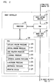
- FIG. 2 presents a diagram of an illustrative robot controller as shown in FIG. 1.
- FIG. 3 presents a flowchart which depicts the operation of the illustrative embodiment.
- FIG. 4 depicts a sampling window comprising a 128 x 128 array of image elements arranged in orthogonal rows and columns.
- FIG. 5 depicts an illustrative relationship of a reference window element to its respective neighbor image elements.
- FIG. 6 depicts an illustrative fiducial as shown in FIG. 1.
- FIG. 7 depicts the illustrative fiducial as shown in FIG. 1 and its angular orientation with respect to the rows and columns of window elements in the sampling window depicted in FIG. 4.
- FIG. 8 depicts an illustrative sampling window which represents an image containing the fiducial shown in FIG. 7.
- FIG. 9 depicts the sampling window shown in FIG. 8 as it has been masked to isolate a portion of the fiducial equal to a vertical period of the fiducial.
- FIG. 10 depicts the sampling window shown in FIG. 9 as it further isolates a set of image elements which partially define the more horizontal edges of the fiducial.
- FIG. 11 depicts the sampling window shown in FIG. 8 as it has been masked to isolate a portion of the fiducial equal to a horizontal period of the fiducial.
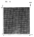
- FIG. 12 depicts the sampling window shown in FIG. 11 as it further isolates a set of image elements which partially define the more vertical edges of the fiducial.
- DSP digital signal processor
- Section II describes an illustrative embodiment of the present invention.
- the illustrative embodiment is part of an automated manufacturing system which inserts components into a printed circuit board with a robot insertion tool.
- the robot be able to place the components into the board in the right place, it is advantageous that the robot be capable of precisely locating the board.
- the illustrative embodiment advantageously locates each printed circuit board by fixing a bearing on the centroid of each of one or more landmarks on each printed circuit board. These landmarks are known as fiducial registration marks or fiducials.
- Section III describes a set of criteria for designing an advantageous fiducial and Section IV describes the process used by the illustrative embodiment to fix a bearing on a fiducial.
- FIG. 1 depicts an illustrative embodiment of the present invention which inserts components into a printed circuit board without human intervention.
- the illustrative embodiment advantageously comprises: printed circuit board 101, a two-or three- dimensional object (such as fiducial 103) on printed circuit board 101 which object appears from the perspective of an input device (such as videocamera 109) to have at least one substantially straight edge, support 105 for substantially holding printed circuit board 101 in the X-Y plane and substantially at a predetermined angular orientation within that plane, videocamera 109 for scanning fiducial 103 and creating a set of video signals which represent the field of view of the videocamera, a monitoring station (such as robot controller 111) for processing the video signals generated by videocamera 109, robot insertion tool 123 (with robot arm 125) for inserting components into printed circuit board 101, lead 107 for carrying the video signals generated by videocamera 109 to robot controller 111, and lead 121 for carrying the signals representing the X-Y coordinates of fiducial 103 to robot
- robot controller 111 advantageously comprises video capture circuitry 255, read-write memory (such as RAM 253), general purpose processor 251, read-only memory (such as ROM 259), and robot drive circuitry 257. It is preferred that video capture circuitry 255 receive a single video frame generated by videocamera 109 and apply the signals in that frame in ordered sequence into RAM 253 to create a "sampling window" (such as that depicted at 401 in FIG. 4) comprising an 128 x 128 array of "image elements" (illustrative ones of which are depicted at 403 in FIG. 4). Processor 251, utilizing one or more procedures stored in ROM 259, advantageously analyzes the image elements in the sampling window to estimate the location of fiducial 103. When processor 251 has estimated the position of fiducial 103, robot drive circuitry 257 conveys that location to robot insertion tool 123 via lead 121.
- video capture circuitry 255 receive a single video frame generated by videocamera 109 and apply the signals in that frame in ordered sequence
- printed circuit board 101 be held by support 105 substantially at a predetermined angular orientation so that printed circuit board 101 substantially lies in the X-Y plane and is substantially restrained from rotating around the Z axis.
- printed circuit board 101 may advantageously comprise a plurality of distinct fiducials so that the orientation and location of printed circuit board 101 may nevertheless be estimated. It will be clear to those skilled in the art how to fabricate embodiments of the present invention when printed circuit board 101 comprises multiple fiducials.
- fiducial 103 on printed circuit board 101 advantageously conforms to the following criteria.
- Fiducial 103 is preferably a solid black square (such as that shown at 103 in FIG. 6) which is set against a highly contrasting (such as white) background which is large enough so that the field of view of videocamera 109 only contains images of fiducial 103 and background 603. It will be clear to those skilled in the art that fiducial 103 may alternately be a rhombus, a trapezoid or any other shape which from the perspective of videocamera 109 appears to have at least one substantially straight edge.
- fiducial 103 it is preferred that the size of fiducial 103 be set so that, when viewed from videocamera 109, fiducial 103 occupies approximately 25% of the field of view of videocamera 109.
- the length of each side, d, of fiducial 103 is advantageous for the length of each side, d, of fiducial 103 to be set so that the distortions introduced into the sampling window because of the physical limitations of videocamera 109 destructively interfere. Therefore, the length of each side of fiducial 103 preferably equals: where n is the number of rows (or columns) in the sampling window and f is the field of view, in linear measure , of videocamera 109 (as projected onto the plane containing the fiducial). In the illustrative embodiment, the sampling window contains 128 rows and 128 columns and has a field of view on the sampling plane of 1.0". From equation (1) the length of each side of fiducial 103 is advantageously set to: It will be clear to those skilled in the art how to set d for different values of f and n.
- fiducial 103 be oriented in the X-Y plane so that when fiducial 103 is viewed through videocamera 109, the sides of fiducial 103 form a predetermined angle, ⁇ , with respect to the axes of the columns and rows of the sampling window.
- This "tilting" of fiducial 103 with respect to the axes of the sampling window is advantageous in that it promotes the destructive interference of distortions caused by the physical limitations of videocamera 109.
- ⁇ be an oblique angle
- the effects of tilting are equivalent for 0°, 45°, 90°, 135° 180°, etc. and for each octant of 45°.
- Angles close to 0° or 45° enable potentially more precise measurements while angles centered between 0° and 45° (i.e., ⁇ 22.5°) enable measurements which are less susceptible to noise.
- ⁇ is chosen to be cotan ⁇ 1(8) which is substantially 7.125°. It will be clear to those skilled in the art how to fabricate embodiments of the present invention which use different angles of ⁇ .
- FIG. 3 presents a flow chart which depicts the operation of the illustrative embodiment depicted in FIGs. 1 and 2.
- the operation of the illustrative embodiment begins at block 301 when printed circuit board 101 is mounted on support 105.
- printed circuit board 101 is advantageously mounted on support 105 so that the above fiducial criteria relating to size and orientation are satisfied.
- videocamera 109 periodically, or on command, scans fiducial 103 and transmits to video capture circuitry 255 over lead 107 a set of video signals which represent the field of view of videocamera 109.
- video capture circuitry 255 applies these signals in ordered sequence into RAM 253 to create sampling window 801. Because each image element in sampling window 801 represents some information about a distinct region in the field of view of videocamera 109, video capture circuitry 255 advantageously assigns an informative "token" (e.g., "Black” or "White”) to each image element so that sampling window 801, in toto , represents the field of view of videocamera 109 when the scan was made.
- an informative "token" e.g., "Black” or "White
- a image element assigned a "BLACK" token is advantageously defined as representing a region which is darker than some threshold intensity (i.e., reflects less than some threshold intensity of light incident on a portion of printed circuit board 101).
- a image element is assigned a "WHITE" token when it is not assigned a BLACK token. It will be clear to those skilled in the art how to fabricate embodiments of the present invention in which the window elements may be assigned characteristics which represent color or gray-scales.
- sampling window 801 which are depicted as black are assigned the token BLACK and represent the field of view of videocamera 109 containing fiducial 103.
- the window elements which are depicted as white are assigned the token WHITE and represent the field of view of videocamera 109 containing the background 603 surrounding fiducial 103.
- sampling window 801 may assume any one of numerous configurations, it is preferred that it comprise a 128 x 128 array of square image elements which are tiled in orthogonal rows and columns.
- Each image element in sampling window 801 is identified by a cartesian coordinate pair. For example, image element (0,127) is the window element in the north-west corner of sampling window 801 and window element (127,127) is the image element in the north-east corner of sampling window 801. It will be clear to those skilled in the art how to fabricate embodiments of the present invention which employ sampling windows with different dimensions (e.g., rectangular or nonorthogonal) or image elements with different shapes.
- processor 251 While video capture circuitry 255 only assigns two tokens ("BLACK” and "WHITE”), it is preferred that processor 251 be capable assigning a third token, "NULL,” to each image element.
- NULL token provides no information about the field of view of videocamera 109 but is used as a placeholder in subsequent calculations.
- processor 251 advantageously estimates the location of the centroid of fiducial 103 in two phases: (1) a "good estimate operation” (block 307) and (2) a “better estimate operation” (block 309).
- the good estimate operation (block 307) estimates the centroid of fiducial 103 by analyzing all of the image elements in sampling window 801. It should be noted that all operations described in this specification to be executed by processor 251 from procedures stored in ROM 259 are performed by the illustrative program listing disclosed in Appendix I. It will be clear to those skilled in the art how to use and/or modify this program listing to fabricate and use other embodiments of the present invention.
- the good estimate operation (block 307) estimates the X-coordinate of the centroid of fiducial 103, X g , by averaging the X-coordinates of all of the image elements assigned a BLACK token.
- the good estimate operation (block 307) estimates the Y-coordinate of the centroid of fiducial 103, Y g , by averaging the Y-coordinates of all of the image elements assigned a BLACK token. It will be clear to those skilled in the art how to program processor 251 to perform the good estimate operation.
- processor 251 After processor 251 performs the good estimate operation (block 307), processor 251 begins executing the better estimate operation (block 309) as shown in FIG. 3. It is preferred that the better estimate operation (block 309) advantageously estimate the centroid of fiducial 103 by analyzing only one or more of those image elements in sampling window 801 which define an edge of fiducial 103. It should be noted that an edge can be represented by either image elements which are assigned BLACK tokens or by image elements which are assigned WHITE tokens.
- the better estimate operation advantageously estimates the X-coordinate of the centroid of fiducial 103, X b , by averaging the X-coordinates of some of the image elements which define the two edges of fiducial 103 which are most parallel to the Y-axis.
- the better estimate operation advantageously estimates the Y-coordinate of the centroid of fiducial 103, Y b , by averaging the Y-coordinates of some of the image elements which define the two edges of fiducial 103 which are most parallel to the X-axis.
- the better estimate operation itself comprises: a "Y-coordinate operation” (block 311) and an "X-coordinate operation” (block 321). It will be clear those skilled in the art how to fabricate embodiments of the invention which perform only one of these two operations or which perform them both in either order, or perform them simultaneously on a multi-tasking or multiprocessor system.
- the Y-coordinate operation (block 311) advantageously comprises: (1) a "duplicate window operation” (block 313), (2) a “vertical masking operation” (block 315), (3) an “edge isolation operation” (block 317) and (4) a “Y-averaging operation” (block 319).
- processor 251 makes a duplicate of sampling window 801 (hereinafter the "duplicate sampling window” - not shown in Figures) in RAM 253. All steps performed by processor 251 during the execution of Y-coodinate operation (block 311) operate on the duplicate sampling window.
- the original sampling window 801 is preserved for the X-coordinate operation (block 321).
- processor 251 After processor 251 has completed the duplicate window operation (block 313), it performs the vertical masking operation (block 315) on the duplicate sampling window.
- the vertical masking operation (block 315) is advantageous in that performs two functions: (1) it allows the image elements which define the more vertical edges of fiducial 103 to be isolated from the image elements which define the more horizontal edges, and (2) it further promotes the destructive interference of distortions due to the physical limitations of videocamera 109.
- the vertical masking operation (block 315) reassigns a NULL token to each image element in the duplicate sampling window which has an X-coordinate below or equal to X L , or above X H .
- Equation (3) advantageously assures that the number of image elements which respectively define the upper and lower edges are equal to "a multiple of the period of the fiducial."
- the period of the fiducial indicates approximately how many columns a portion of the edge of the fiducial must traverse to traverse one row. It is preferred that the number of image elements used in the Y-averaging operation (block 319) equal an integral multiple of the period of the fiducial because it further causes the distortions caused by by the physical limitations of videocamera 109 to cancel.
- processor 251 assigns all window elements with X-coordinates greater than 92 or less than or equal to 60 a NULL token.
- the masked duplicate sampling window is depicted at 901 in FIG. 9. Those image elements which are assigned NULL tokens appear with cross-hatches. At this point the vertical masking operation (block 315) is complete.
- the edge isolation operation (block 317) advantageously identifies a subset of the image elements in the masked duplicate sampling window as "edge image elements.”
- an edge image element is defined as a image element which defines an edge on fiducial 103.
- an edge image element is advantageously defined as a image element which is assigned a BLACK token and which has at least one "neighbor image element" which is assigned a WHITE token.
- a image element which is assigned a NULL or a WHITE token can never be an edge image element.
- a neighbor image element is defined as a image element which has a coordinate relationship with respect to another image element.
- image element 501 is advantageously defined to have four neighbor image elements: image element 503 (to the north of image element 501), image element 505 (to the east of window element 501), image element 507 (to the south of image element 501) and image element 509 (to the west of image element 501). It will be clear to those skilled in the art how to program processor 251 to perform the edge isolation operation (block 317).
- neighbor image elements e.g., includes image elements to the north-east, south-east, south-west and north-west of a given image element.
- the result is the duplicate sampling window depicted in FIG. 10 (all of the image elements are assigned a WHITE token and appear white except for the edge image elements which are assigned a BLACK token and appear black).
- the last step in the Y-coordinate operation is the Y-averaging operation (block 319).
- processor 251 determines the better estimate, Y b , of the Y-coordinate of the centroid of fiducial 103 by averaging the Y-coordinates of all of the edge image elements (i.e., those window elements in the duplicate sampling window, as depicted in FIG. 10, which are assigned a BLACK token).
- the X-coordinate operation advantageously comprises: (1) a "horizontal masking operation” (block 323), (2) an “edge isolation operation” (block 325) and (3) a "X-averaging operation” (block 327).
- Processor 521 begins the X-coordinate operation (block 321) by performing the horizontal masking operation (block 315) on the original sampling window 801 which was left undisturbed by the Y-coordinate operation (block 311).
- the horizontal masking operation (block 315) is analagous to the vertical masking operation (block 315) and is advantageous for analagous reasons.
- the horizontal masking operation (block 315) reassigns a NULL token to each image element in the duplicate sampling window which has an Y-coordinate below or equal to Y L , or above Y H .
- processor 251 assigns all window elements with Y-coordinates greater than 87 or less than or equal to 55 a NULL token.
- the masked duplicate sampling window is depicted at 1101 in FIG. 11. Those image elements which are assigned NULL tokens appear with cross-hatches. At this point the horizontal masking operation (block 323) is complete.
- the edge isolation operation (block 325) is identical to the edge isolation operation (block 317) in the Y-coordinate operation (block 311) and produces from the masked sampling window of FIG. 11 the sampling window depicted in FIG. 12 (all of the image elements are assigned a WHITE token and appear white except for the edge window elements which are assigned a BLACK token and appear black).
- the last step in the X-coordinate operation is the X-averaging operation (block 327).
- processor 251 determines the better estimate, X b , of the X-coordinate of the centroid of fiducial 103 by averaging the X-coordinates of all of the edge image elements (i.e., those window elements in the duplicate sampling window, as depicted in FIG. 12, which are assigned a BLACK token).
- Robot drive circuitry 257 can relay those coodinates, via lead 121 to robot insertion tool 123 for use in inserting components into printed circuit board 101.
- Robot insertion tool 123 advantageously comprises means for moving robot arm 125 in the X and Y directions so that robot arm 125 may populate printed circuit board 101 according to the specifics of the particular embodiment.
Landscapes
- Engineering & Computer Science (AREA)
- Computer Vision & Pattern Recognition (AREA)
- Physics & Mathematics (AREA)
- General Physics & Mathematics (AREA)
- Theoretical Computer Science (AREA)
- Image Processing (AREA)
- Registering Or Overturning Sheets (AREA)
- Supply And Installment Of Electrical Components (AREA)
- Image Analysis (AREA)
Applications Claiming Priority (2)
| Application Number | Priority Date | Filing Date | Title |
|---|---|---|---|
| US99630392A | 1992-12-23 | 1992-12-23 | |
| US996303 | 1992-12-23 |
Publications (3)
| Publication Number | Publication Date |
|---|---|
| EP0604052A2 true EP0604052A2 (fr) | 1994-06-29 |
| EP0604052A3 EP0604052A3 (fr) | 1995-07-26 |
| EP0604052B1 EP0604052B1 (fr) | 2001-08-08 |
Family
ID=25542749
Family Applications (1)
| Application Number | Title | Priority Date | Filing Date |
|---|---|---|---|
| EP93309753A Expired - Lifetime EP0604052B1 (fr) | 1992-12-23 | 1993-12-06 | Une méthode et un système pour situer des objets avec une précision inférieure au pixel |
Country Status (4)
| Country | Link |
|---|---|
| US (1) | US5557690A (fr) |
| EP (1) | EP0604052B1 (fr) |
| JP (1) | JP2816304B2 (fr) |
| DE (1) | DE69330550T2 (fr) |
Families Citing this family (27)
| Publication number | Priority date | Publication date | Assignee | Title |
|---|---|---|---|---|
| US5949924A (en) * | 1995-10-06 | 1999-09-07 | Ricoh Company, Ltd. | Image processing apparatus, method and computer program product |
| US6259827B1 (en) | 1996-03-21 | 2001-07-10 | Cognex Corporation | Machine vision methods for enhancing the contrast between an object and its background using multiple on-axis images |
| US6075881A (en) | 1997-03-18 | 2000-06-13 | Cognex Corporation | Machine vision methods for identifying collinear sets of points from an image |
| US5974169A (en) | 1997-03-20 | 1999-10-26 | Cognex Corporation | Machine vision methods for determining characteristics of an object using boundary points and bounding regions |
| US6608647B1 (en) | 1997-06-24 | 2003-08-19 | Cognex Corporation | Methods and apparatus for charge coupled device image acquisition with independent integration and readout |
| US6381375B1 (en) | 1998-02-20 | 2002-04-30 | Cognex Corporation | Methods and apparatus for generating a projection of an image |
| US6381366B1 (en) | 1998-12-18 | 2002-04-30 | Cognex Corporation | Machine vision methods and system for boundary point-based comparison of patterns and images |
| US6687402B1 (en) | 1998-12-18 | 2004-02-03 | Cognex Corporation | Machine vision methods and systems for boundary feature comparison of patterns and images |
| US6684402B1 (en) | 1999-12-01 | 2004-01-27 | Cognex Technology And Investment Corporation | Control methods and apparatus for coupling multiple image acquisition devices to a digital data processor |
| US6748104B1 (en) | 2000-03-24 | 2004-06-08 | Cognex Corporation | Methods and apparatus for machine vision inspection using single and multiple templates or patterns |
| US20020120728A1 (en) * | 2000-12-22 | 2002-08-29 | Jason Braatz | Method and apparatus for network-enablement of devices using device intelligence and network architecture |
| US7006669B1 (en) | 2000-12-31 | 2006-02-28 | Cognex Corporation | Machine vision method and apparatus for thresholding images of non-uniform materials |
| JP3741013B2 (ja) * | 2001-09-17 | 2006-02-01 | ウシオ電機株式会社 | 蛇行修正機構を備えた帯状ワークの露光装置 |
| US7228428B2 (en) * | 2001-12-14 | 2007-06-05 | Xerox Corporation | Method and apparatus for embedding encrypted images of signatures and other data on checks |
| AU2003900180A0 (en) * | 2003-01-16 | 2003-01-30 | Silverbrook Research Pty Ltd | Method and apparatus (dam001) |
| CN100334592C (zh) * | 2004-12-30 | 2007-08-29 | 财团法人工业技术研究院 | 非对应性基材的视觉对位方法 |
| US7796116B2 (en) | 2005-01-12 | 2010-09-14 | Thinkoptics, Inc. | Electronic equipment for handheld vision based absolute pointing system |
| US7639861B2 (en) | 2005-09-14 | 2009-12-29 | Cognex Technology And Investment Corporation | Method and apparatus for backlighting a wafer during alignment |
| WO2007035798A2 (fr) | 2005-09-19 | 2007-03-29 | Calypso Medical Technologies, Inc. | Appareils et procedes permettant d'implanter des objets, tels que des marqueurs d'implantation bronchoscopique, dans les poumons de patients |
| US8111904B2 (en) | 2005-10-07 | 2012-02-07 | Cognex Technology And Investment Corp. | Methods and apparatus for practical 3D vision system |
| US8913003B2 (en) | 2006-07-17 | 2014-12-16 | Thinkoptics, Inc. | Free-space multi-dimensional absolute pointer using a projection marker system |
| US8162584B2 (en) | 2006-08-23 | 2012-04-24 | Cognex Corporation | Method and apparatus for semiconductor wafer alignment |
| US9176598B2 (en) | 2007-05-08 | 2015-11-03 | Thinkoptics, Inc. | Free-space multi-dimensional absolute pointer with improved performance |
| JP5457665B2 (ja) * | 2008-12-22 | 2014-04-02 | 株式会社日立ハイテクインスツルメンツ | 電子部品装着装置 |
| US9411779B2 (en) * | 2012-09-28 | 2016-08-09 | Illinois Tool Works Inc. | Method of dispensing material based on edge detection |
| US9919165B2 (en) | 2014-05-07 | 2018-03-20 | Varian Medical Systems, Inc. | Systems and methods for fiducial to plan association |
| US10043284B2 (en) * | 2014-05-07 | 2018-08-07 | Varian Medical Systems, Inc. | Systems and methods for real-time tumor tracking |
Citations (4)
| Publication number | Priority date | Publication date | Assignee | Title |
|---|---|---|---|---|
| US4621406A (en) | 1983-02-28 | 1986-11-11 | Matsushita Electric Industrial Co., Ltd. | Electronic component insertion apparatus |
| US4868975A (en) | 1988-12-05 | 1989-09-26 | Ag Communication Systems Corporation | Tool for inserting dual in-line packaged circuits into printed circuit board sockets |
| US4984355A (en) | 1989-03-06 | 1991-01-15 | Unisys Corporation | Tool for inserting/extracting package from socket on PC board |
| US5031224A (en) | 1987-07-10 | 1991-07-09 | Siemens Aktiengesellschaft | Flexible recognition of subject structures in color and picture half-tone images |
Family Cites Families (8)
| Publication number | Priority date | Publication date | Assignee | Title |
|---|---|---|---|---|
| US4209830A (en) * | 1976-04-19 | 1980-06-24 | Tokyo Shibaura Electric Co., Ltd. | Fine object having position and direction sensing mark and a system for detecting the position and direction of the sensing mark |
| JPS63104348A (ja) * | 1986-10-21 | 1988-05-09 | Toko Inc | 半導体装置 |
| US5119435A (en) * | 1987-09-21 | 1992-06-02 | Kulicke And Soffa Industries, Inc. | Pattern recognition apparatus and method |
| US4845558A (en) * | 1987-12-03 | 1989-07-04 | Kla Instruments Corporation | Method and apparatus for detecting defects in repeated microminiature patterns |
| US4969200A (en) * | 1988-03-25 | 1990-11-06 | Texas Instruments Incorporated | Target autoalignment for pattern inspector or writer |
| US4972311A (en) * | 1988-08-15 | 1990-11-20 | Kulicke And Soffa Industries Inc. | X-Y table error mapping apparatus and method |
| JP2776860B2 (ja) * | 1989-01-11 | 1998-07-16 | 株式会社日立製作所 | 電子部品装着装置及び装着方法 |
| JPH083405B2 (ja) * | 1989-06-30 | 1996-01-17 | 松下電器産業株式会社 | リード位置認識装置 |
-
1993
- 1993-12-06 DE DE69330550T patent/DE69330550T2/de not_active Expired - Fee Related
- 1993-12-06 EP EP93309753A patent/EP0604052B1/fr not_active Expired - Lifetime
- 1993-12-22 JP JP5345562A patent/JP2816304B2/ja not_active Expired - Fee Related
-
1994
- 1994-06-23 US US08/265,979 patent/US5557690A/en not_active Expired - Lifetime
Patent Citations (4)
| Publication number | Priority date | Publication date | Assignee | Title |
|---|---|---|---|---|
| US4621406A (en) | 1983-02-28 | 1986-11-11 | Matsushita Electric Industrial Co., Ltd. | Electronic component insertion apparatus |
| US5031224A (en) | 1987-07-10 | 1991-07-09 | Siemens Aktiengesellschaft | Flexible recognition of subject structures in color and picture half-tone images |
| US4868975A (en) | 1988-12-05 | 1989-09-26 | Ag Communication Systems Corporation | Tool for inserting dual in-line packaged circuits into printed circuit board sockets |
| US4984355A (en) | 1989-03-06 | 1991-01-15 | Unisys Corporation | Tool for inserting/extracting package from socket on PC board |
Also Published As
| Publication number | Publication date |
|---|---|
| US5557690A (en) | 1996-09-17 |
| JP2816304B2 (ja) | 1998-10-27 |
| JPH06227711A (ja) | 1994-08-16 |
| DE69330550T2 (de) | 2002-05-16 |
| EP0604052A3 (fr) | 1995-07-26 |
| DE69330550D1 (de) | 2001-09-13 |
| EP0604052B1 (fr) | 2001-08-08 |
Similar Documents
| Publication | Publication Date | Title |
|---|---|---|
| EP0604052B1 (fr) | Une méthode et un système pour situer des objets avec une précision inférieure au pixel | |
| EP0218259B1 (fr) | Méthode et appareil pour calculer la position et l'orientation par combinaison de particularités de coupes partielles | |
| JP4901903B2 (ja) | 三次元検査システム | |
| US4593406A (en) | Automatic image acquisition processor and method | |
| JP3515199B2 (ja) | 欠陥検査装置 | |
| WO1999015854A1 (fr) | Procedes de vision par ordinateur utilisant une fonction de retroaction pour determiner les positions d'etalonnage de plusieurs cameras procedant a l'acquisition d'images d'un objet commun | |
| US9972101B2 (en) | Reconstruction of three dimensional model of an object from surface or slice scans compensating for motion blur | |
| US5978080A (en) | Machine vision methods using feedback to determine an orientation, pixel width and pixel height of a field of view | |
| CN1613285A (zh) | 具有元件布局检查功能的抓取式设备 | |
| EP0157299B1 (fr) | Appareil d'exploitation d'images | |
| JP3138080B2 (ja) | 視覚センサの自動キャリブレーション装置 | |
| EP3542204B1 (fr) | Procédé et système pour détecter une précision de placement de substrat | |
| CN115965594B (zh) | 筛网自动焊接轨迹点检测方法及装置 | |
| Andersson | A low-latency 60 Hz stereo vision system for real-time visual control | |
| KR102845241B1 (ko) | 다수의 홀이 형성된 기판의 홀 위치 검사 시스템 | |
| JPH06347232A (ja) | プリント基板外観検査装置 | |
| US20180293764A1 (en) | Reconstruction of three dimensional model of an object compensating for object orientation changes between surface or slice scans | |
| JPH0652167B2 (ja) | 画像処理方法 | |
| JP2708621B2 (ja) | 基板の位置検出方法および基板への部品搭載装置 | |
| JPH04225300A (ja) | 画像位置決め方法 | |
| JP3345496B2 (ja) | 電子部品の位置検出方法 | |
| JPS62102984A (ja) | ロボットの手首部位置決め方法 | |
| JPS63115400A (ja) | 半導体装置の姿勢検出装置 | |
| JPH0685495A (ja) | 電子部品搭載装置と、それにおける部品位置決め方法 | |
| JP2797703B2 (ja) | 電子部品の検査枠の設定方法 |
Legal Events
| Date | Code | Title | Description |
|---|---|---|---|
| PUAI | Public reference made under article 153(3) epc to a published international application that has entered the european phase |
Free format text: ORIGINAL CODE: 0009012 |
|
| AK | Designated contracting states |
Kind code of ref document: A2 Designated state(s): DE FR GB IT |
|
| PUAL | Search report despatched |
Free format text: ORIGINAL CODE: 0009013 |
|
| AK | Designated contracting states |
Kind code of ref document: A3 Designated state(s): DE FR GB IT |
|
| 17P | Request for examination filed |
Effective date: 19960111 |
|
| 17Q | First examination report despatched |
Effective date: 19980819 |
|
| RIC1 | Information provided on ipc code assigned before grant |
Free format text: 7G 06T 7/00 A |
|
| GRAG | Despatch of communication of intention to grant |
Free format text: ORIGINAL CODE: EPIDOS AGRA |
|
| RIC1 | Information provided on ipc code assigned before grant |
Free format text: 7G 06T 7/00 A |
|
| GRAG | Despatch of communication of intention to grant |
Free format text: ORIGINAL CODE: EPIDOS AGRA |
|
| GRAH | Despatch of communication of intention to grant a patent |
Free format text: ORIGINAL CODE: EPIDOS IGRA |
|
| GRAH | Despatch of communication of intention to grant a patent |
Free format text: ORIGINAL CODE: EPIDOS IGRA |
|
| GRAA | (expected) grant |
Free format text: ORIGINAL CODE: 0009210 |
|
| AK | Designated contracting states |
Kind code of ref document: B1 Designated state(s): DE FR GB IT |
|
| REF | Corresponds to: |
Ref document number: 69330550 Country of ref document: DE Date of ref document: 20010913 |
|
| PG25 | Lapsed in a contracting state [announced via postgrant information from national office to epo] |
Ref country code: DE Free format text: LAPSE BECAUSE OF FAILURE TO SUBMIT A TRANSLATION OF THE DESCRIPTION OR TO PAY THE FEE WITHIN THE PRESCRIBED TIME-LIMIT Effective date: 20011109 |
|
| REG | Reference to a national code |
Ref country code: GB Ref legal event code: IF02 |
|
| ET | Fr: translation filed | ||
| PLBE | No opposition filed within time limit |
Free format text: ORIGINAL CODE: 0009261 |
|
| STAA | Information on the status of an ep patent application or granted ep patent |
Free format text: STATUS: NO OPPOSITION FILED WITHIN TIME LIMIT |
|
| 26N | No opposition filed | ||
| PGFP | Annual fee paid to national office [announced via postgrant information from national office to epo] |
Ref country code: IT Payment date: 20071222 Year of fee payment: 15 |
|
| PGFP | Annual fee paid to national office [announced via postgrant information from national office to epo] |
Ref country code: GB Payment date: 20071218 Year of fee payment: 15 |
|
| PGFP | Annual fee paid to national office [announced via postgrant information from national office to epo] |
Ref country code: DE Payment date: 20071221 Year of fee payment: 15 |
|
| PGFP | Annual fee paid to national office [announced via postgrant information from national office to epo] |
Ref country code: FR Payment date: 20071217 Year of fee payment: 15 |
|
| GBPC | Gb: european patent ceased through non-payment of renewal fee |
Effective date: 20081206 |
|
| REG | Reference to a national code |
Ref country code: FR Ref legal event code: ST Effective date: 20090831 |
|
| PG25 | Lapsed in a contracting state [announced via postgrant information from national office to epo] |
Ref country code: DE Free format text: LAPSE BECAUSE OF NON-PAYMENT OF DUE FEES Effective date: 20090701 |
|
| PG25 | Lapsed in a contracting state [announced via postgrant information from national office to epo] |
Ref country code: GB Free format text: LAPSE BECAUSE OF NON-PAYMENT OF DUE FEES Effective date: 20081206 |
|
| PG25 | Lapsed in a contracting state [announced via postgrant information from national office to epo] |
Ref country code: FR Free format text: LAPSE BECAUSE OF NON-PAYMENT OF DUE FEES Effective date: 20081231 |
|
| PG25 | Lapsed in a contracting state [announced via postgrant information from national office to epo] |
Ref country code: IT Free format text: LAPSE BECAUSE OF NON-PAYMENT OF DUE FEES Effective date: 20081206 |