EP0604093A1 - Système de projection de réduction catadioptrique - Google Patents
Système de projection de réduction catadioptrique Download PDFInfo
- Publication number
- EP0604093A1 EP0604093A1 EP93310039A EP93310039A EP0604093A1 EP 0604093 A1 EP0604093 A1 EP 0604093A1 EP 93310039 A EP93310039 A EP 93310039A EP 93310039 A EP93310039 A EP 93310039A EP 0604093 A1 EP0604093 A1 EP 0604093A1
- Authority
- EP
- European Patent Office
- Prior art keywords
- lens
- lens group
- reflection mirror
- concave reflection
- refractive power
- Prior art date
- Legal status (The legal status is an assumption and is not a legal conclusion. Google has not performed a legal analysis and makes no representation as to the accuracy of the status listed.)
- Granted
Links
- 230000003287 optical effect Effects 0.000 title claims abstract description 130
- 230000009467 reduction Effects 0.000 title claims abstract description 43
- 238000003384 imaging method Methods 0.000 claims abstract description 24
- 230000005499 meniscus Effects 0.000 claims description 73
- 230000004075 alteration Effects 0.000 claims description 36
- 239000011521 glass Substances 0.000 claims description 12
- 239000000463 material Substances 0.000 claims description 10
- VYPSYNLAJGMNEJ-UHFFFAOYSA-N Silicium dioxide Chemical compound O=[Si]=O VYPSYNLAJGMNEJ-UHFFFAOYSA-N 0.000 claims 4
- WUKWITHWXAAZEY-UHFFFAOYSA-L calcium difluoride Chemical compound [F-].[F-].[Ca+2] WUKWITHWXAAZEY-UHFFFAOYSA-L 0.000 claims 3
- 239000010436 fluorite Substances 0.000 claims 3
- 206010010071 Coma Diseases 0.000 description 32
- 238000010276 construction Methods 0.000 description 8
- 230000001902 propagating effect Effects 0.000 description 6
- 230000007423 decrease Effects 0.000 description 3
- 238000004519 manufacturing process Methods 0.000 description 3
- 239000007787 solid Substances 0.000 description 3
- 238000005452 bending Methods 0.000 description 2
- 230000004048 modification Effects 0.000 description 2
- 238000012986 modification Methods 0.000 description 2
- 239000004065 semiconductor Substances 0.000 description 2
- 230000015572 biosynthetic process Effects 0.000 description 1
- 238000010586 diagram Methods 0.000 description 1
- 238000006073 displacement reaction Methods 0.000 description 1
- 230000000694 effects Effects 0.000 description 1
- 230000007246 mechanism Effects 0.000 description 1
- 238000001393 microlithography Methods 0.000 description 1
- 229920002120 photoresistant polymer Polymers 0.000 description 1
Images








Classifications
-
- G—PHYSICS
- G02—OPTICS
- G02B—OPTICAL ELEMENTS, SYSTEMS OR APPARATUS
- G02B17/00—Systems with reflecting surfaces, with or without refracting elements
- G02B17/08—Catadioptric systems
- G02B17/0804—Catadioptric systems using two curved mirrors
- G02B17/0812—Catadioptric systems using two curved mirrors off-axis or unobscured systems in which all of the mirrors share a common axis of rotational symmetry
-
- G—PHYSICS
- G02—OPTICS
- G02B—OPTICAL ELEMENTS, SYSTEMS OR APPARATUS
- G02B17/00—Systems with reflecting surfaces, with or without refracting elements
- G02B17/08—Catadioptric systems
- G02B17/0892—Catadioptric systems specially adapted for the UV
-
- G—PHYSICS
- G03—PHOTOGRAPHY; CINEMATOGRAPHY; ANALOGOUS TECHNIQUES USING WAVES OTHER THAN OPTICAL WAVES; ELECTROGRAPHY; HOLOGRAPHY
- G03F—PHOTOMECHANICAL PRODUCTION OF TEXTURED OR PATTERNED SURFACES, e.g. FOR PRINTING, FOR PROCESSING OF SEMICONDUCTOR DEVICES; MATERIALS THEREFOR; ORIGINALS THEREFOR; APPARATUS SPECIALLY ADAPTED THEREFOR
- G03F7/00—Photomechanical, e.g. photolithographic, production of textured or patterned surfaces, e.g. printing surfaces; Materials therefor, e.g. comprising photoresists; Apparatus specially adapted therefor
- G03F7/70—Microphotolithographic exposure; Apparatus therefor
- G03F7/70216—Mask projection systems
- G03F7/70225—Optical aspects of catadioptric systems, i.e. comprising reflective and refractive elements
Definitions
- the present invention relates to a catadioptric optical system and, more particularly, to an imaging optical system for performing reduction projection.
- the reduction optical system disclosed in U.S. Patent 4,953,960 comprises a combination of a concave mirror and a lens system. Since this optical system attains reduction mainly using the concave mirror, the aberration is large, and a number of lenses must be combined to correct the aberrations.
- an object of the present invention to provide a catadioptric reduction projection optical system, which has an excellent imaging performance as an optical system used in the manufacture of a semiconductor device, and has a large numerical aperture.
- a catadioptric reduction projection optical system comprises: a first partial optical system including, in succession from the object side, a first lens group G1 of positive refractive power and a first concave reflection mirror M1, and for forming a primary image of an object; and a second partial optical system including, in succession from the object side, a second concave reflection mirror M2 and a third lens group G3 of positive refractive power, and for re-imaging the primary image, wherein a second lens group G2 of positive or negative refractive power is arranged in an optical path between the first and second concave reflection mirrors M1 and M2.
- the first and second partial optical systems each have a concave reflection mirror having chief refractive power and a lens group (first or third lens group G1 or G3) of positive refractive power, and both make reduction imaging possible. Therefore, a predetermined reduction factor can be obtained as a whole system without forcing each partial optical system to bear a great burden in aberration correction. For this reason, it is possible to simplify the optical construction and yet maintain an excellent imaging performance.
- a catadioptric reduction projection optical system comprises: a first partial optical system including, in succession from the object side, a first lens group G1 of positive refractive power and a first concave reflection mirror M1, and for forming a primary image of an object; and a second partial optical system including, in succession from the object side, a second concave reflection mirror M2 and a third lens group G3 of positive refractive power, and for re-imaging the primary image, wherein a second lens group G2 of positive or negative refractive power is arranged in an optical path between the first and second concave reflection mirrors M1 and M2, and at least one of the first to third lens groups G1 to G3 is constituted by at least two different glass materials.
- chromatic aberration is corrected satisfactorily, and the imaging performance can be further improved.
- the catadioptric reduction projection optical system according to the present invention preferably satisfies: 0.05 ⁇ ⁇ G3 ⁇ 0.6 where ⁇ G3 is the magnification of the third lens group G3 of positive refractive power.
- ⁇ G3 is the magnification of the third lens group G3 of positive refractive power.
- the physically constructible optical system means an optical system in which optical members do not interfere with each other in an arrangement of optical members constituting the catadioptric reduction projection optical system.
- ⁇ G3 exceeds the upper limit of the above-mentioned condition (1), a light beam propagating between the concave reflection mirrors M1 and M2 considerably overlaps a light beam propagating from the concave reflection mirror M2 to the secondary image surface, and the arrangement of optical members constituting the catadioptric reduction projection optical system cannot be realized.
- ⁇ G3 is set below the lower limit of the above-mentioned condition (1), the refractive power of the third lens group G3 increases, and coma and chromatic aberration are generated considerably.
- the catadioptric reduction projection optical system according to the present invention preferably satisfies: -2.0 ⁇ ⁇ M1 ⁇ -0.7 where ⁇ M1 is the magnification of the first concave reflection mirror M1.
- This condition defines a proper magnification of the first concave reflection mirror M1.
- ⁇ M1 exceeds the upper limit of the condition (2), the refractive power of the first concave reflection mirror M1 increases, and aberrations, especially, spherical aberration and coma, generated by the first concave reflection mirror M1 increase.
- the negative refractive power of a refracting optical system must be strengthened, and it becomes difficult to satisfactorily correct these aberrations.
- the catadioptric reduction projection optical system according to the present invention preferably satisfies: -2.5 ⁇ ⁇ M2 ⁇ -0.7 where ⁇ M2 is the magnification of the second concave reflection mirror M2.
- This condition (3) defines a proper magnification of the second reflection mirror M2.
- ⁇ M2 exceeds the upper limit of the condition (3), the refractive power of the concave reflection mirror M2 increases, and aberrations, especially, spherical aberration and coma, generated by the this concave reflection mirror M2 increase. As a result, it becomes difficult to satisfactorily correct the aberrations.
- a light beam propagating toward the concave reflection mirror M2 considerably overlaps a light beam propagating from the concave reflection mirror M2 toward the secondary image surface, and it becomes difficult to obtain a physically constructible optical system.
- ⁇ M2 When ⁇ M2 is set below the lower limit of the condition, the refractive power of the concave reflection mirror M2 decreases, and the refracting optical system must compensate for the decrease in refractive power, thus losing merits of the reflecting optical system. At this time, the construction of the refracting optical system is more complicated, and it also becomes difficult to attain aberration correction.
- the first lens group G1 is arranged in the vicinity of the object surface, has a function of maintaining telecentric characteristics, and corrects distortion.
- the second and third lens groups G2 and G3 contribute to formation of the reduced image and to correction of the Petzval sum.
- the second lens group G2 functions as a so-called field lens, and allows a light beam from a position near the optical axis of the first concave reflection mirror M1 to pass therethrough.
- the light beam through second concave mirror M2 at a position near the optical axis and generation of aberration in the second concave reflection mirror M2 can be prevented.
- the negative distortion generated in the second and third lens groups G2 and G3 is corrected by the positive distortion of the first lens group G1.
- Lens groups (fourth and fifth lens groups G4 and G5) provisionally disposed in the vicinity of the concave reflection mirrors are effective to correct higher order spherical aberration generated by the concave reflection mirrors.
- the concave reflection mirror is constituted to be a non-spherical mirror, since aberration generated by the concave reflection mirror is minimized, the fourth and fifth lens groups G4 and G5 may be omitted.
- Fig. 1 is an optical path diagram showing a construction of the first embodiment according to the present invention.
- a light beam from an object surface passes through a first lens group G1 which comprises a biconvex positive lens L11, a positive meniscus lens L12 having a convex surface facing the object side, and a negative meniscus lens L13 having a convex surface facing the object side, and has positive refractive power as a whole, and is reflected by a first concave reflection mirror M1 having a magnification slightly smaller than unity.
- the optical path is bent by a planar reflection mirror M3.
- the first lens group G1 mainly functions to correct distortion and to maintain telecentric characteristics.
- the first lens group G1 and the first concave reflection mirror M1 form a primary reduced image I1.
- a light beam from the primary image I1 passes through a second lens group G2 comprising a positive meniscus lens L21 having a convex surface facing the primary image side, a negative meniscus lens L22 having a concave surface facing the primary image side, and a biconvex positive lens L23, and reaches a second concave reflection mirror M2 having an enlargement factor via a fourth lens group G4 having negative refractive power.
- the second lens group G2 mainly functions to correct distortion and curvature of field, and functions as a field lens.
- the fourth lens group G4 comprises a negative meniscus lens having a convex surface facing the second concave reflection mirror M2 side, and functions to correct aberrations caused by the first and second concave reflection mirrors M1 and M2.
- the light beam reflected by the second concave reflection mirror M2 passes through the fourth lens group G4 again, and then becomes incident on a third lens group G3 having positive refractive power.
- the third lens group G3 comprises, in succession from the incident side of a light beam, a negative meniscus lens L31 having a concave lens facing the incident side, a positive meniscus lens L32 having a convex surface facing the incident side, a positive meniscus lens L33 having a convex surface facing the incident side, a biconcave negative lens L34, a biconvex positive lens L35, a positive meniscus lens L36 having a convex surface facing the incident side, and a positive meniscus lens L37 having a convex surface facing the incident side.
- the third lens group G3 has a positive Petzval sum to cancel the function of making the Petzval sum by the first and second concave reflection mirrors M1 and M2 negative.
- the third lens group G3 forms a second image I2 in a larger reduction scale than that of the primary image I1.
- the first lens group G1 and the first concave reflection mirror M1 constitute a first partial optical system
- the second concave reflection mirror M2 and the third lens group G3 constitute a second partial optical system
- the second lens group G2 is disposed in the optical path between the first and second concave reflection mirrors M1 and M2.
- the planar reflection mirror M3 for bending the optical path is obliquely disposed near the first lens group G1 at an angle of 45° with respect to an optical axis Ax1 of the first partial optical system, so that an optical axis Ax2 of the second partial optical system extends perpendicular to the optical axis Ax1 of the first partial optical system.
- the second lens group G2 is disposed only one side of the second partial optical system so as to focus light reflected by the first concave reflection mirror M1 without shielding a light beam propagating toward the second concave reflection mirror M2.
- the first embodiment has a reduction factor of +0.20 or 1/5 as a whole, and achieves a numerical aperture of (N.A.) of 0.45 in a ring-shaped view field centered at an arc having a radius of 20 mm from the optical axis.
- Table 1 below shows data of the first embodiment.
- the signs of the refractive index and the plane-to-plane distance are reversed by reflection by the concave reflection mirror.
- the refractive index of each glass material corresponds to that at the wavelength (248 nm) of KrF. Note that the position of the planar reflection mirror M3 for bending the optical path is omitted since it is not essential in the optical design.
- Fig. 2 shows coma for explaining the imaging performance of the first embodiment.
- Fig. 2 shows coma in the meridional direction at the center of the ring-shaped view field. As can be seen from Fig. 2, this embodiment maintains an excellent imaging performance.
- a light beam from the object surface passes through a first lens group G1 which comprises a biconvex positive lens L11, a positive meniscus lens L12 having a convex surface facing the incident side of the light beam, and a negative meniscus lens L13 having a convex surface facing the incident side, and has positive refractive power as a whole, and is then reflected by a first concave reflection mirror M1 having a magnification slightly smaller than unity.
- the reflected light beam is deflected by a planar reflection mirror M3 which is obliquely disposed at 45° with respect to an optical axis Ax1 of the first lens group G1, and then becomes incident on a second lens group G2 of negative refractive power.
- the second lens group G2 comprises, in succession from the incident side of a light beam, a negative lens L21 having a substantially plano-concave shape, a negative meniscus lens L22 having a concave surface facing the incident side, and a positive meniscus lens L23 having a concave surface facing the incident side, and forms a primary image I1 as a reduced image of an object in the negative lens L21.
- the light beam emerging from the second lens group G2 is reflected by a second concave reflection mirror M2 having a magnification larger than unity via a fourth lens group G4 of negative refractive power.
- the fourth lens group G4 comprises a negative meniscus lens having a convex surface facing the second concave reflection mirror M2.
- the light beam reflected by the second concave reflection mirror M2 is deflected by a planar reflection mirror M4, which is obliquely arranged at 45° with respect to an optical axis Ax2 of the second lens group G2, via the fourth lens group G4 again, and becomes incident on a third lens group G3 of positive refractive power.
- the third lens group G3 comprises, in succession from the incident side of a light beam, a biconvex positive lens L31, a negative meniscus lens L32 having a concave surface facing the incident side, a biconvex positive lens L33, a negative meniscus lens L34 having a concave surface facing the incident side, a positive meniscus lens L35 having a concave surface facing the incident side, a negative meniscus lens L36 having a concave surface facing the incident side, and a positive meniscus lens L37 having a convex surface facing the incident side, and forms a secondary image I2 in a larger reduction scale than that of the primary image I1.
- the negative lens L21 in the second lens group G2 is arranged at only one side so as not to shield a light beam passing through the first lens group G1.
- the second embodiment has a reduction factor of +0.20 or 1/5 as a whole, and achieves a numerical aperture of (N.A.) of 0.45 in a ring-shaped view field centered at an arc having a radius of 20 mm from the optical axis.
- the refractive index of each glass material corresponds to that at the wavelength (193 nm) of ArF.
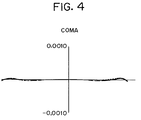
- Fig. 4 shows coma for explaining the imaging performance of the second embodiment.
- Fig. 4 shows coma in the meridional direction at the center of the ring-shaped view field. Note that a broken curve in Fig. 4 represents coma at 193.3 nm, a broken curve longer the curve representing coma at 193.3 nm represents coma at 192.9 nm, and a dotted curve represents coma at 193.7 nm.
- the second embodiment can achieve correction of chromatic aberration within a range of ⁇ 0.4 nm at the wavelength of ArF, and maintains an excellent imaging performance.
- a light beam from the object surface passes through a first lens group G1 which comprises a positive meniscus lens L11 having a concave surface facing the incident side of a light beam, a biconvex positive lens L12, and a biconcave negative lens L13, and has positive refractive power as a whole, and becomes incident on a first concave reflection mirror M1, which has a magnification slightly smaller than unity, via a fifth lens group G5.
- a first lens group G1 which comprises a positive meniscus lens L11 having a concave surface facing the incident side of a light beam, a biconvex positive lens L12, and a biconcave negative lens L13, and has positive refractive power as a whole, and becomes incident on a first concave reflection mirror M1, which has a magnification slightly smaller than unity, via a fifth lens group G5.
- the fifth lens group G5 comprises a negative meniscus lens having a convex surface facing the first concave reflection mirror M1, and functions to correct aberration generated by the first concave reflection mirror M1 and second concave reflection mirror M2.
- the light beam reflected by the first concave reflection mirror M1 is deflected by a planar reflection mirror M3 via the fifth lens group G5 again, and becomes incident on a second lens group G2 of positive refractive power.
- the planar reflection mirror M3 is obliquely arranged at 45° with respect to an optical axis Ax1 of the first lens group G1 in the optical path between the fifth and first lens group G5 and G1.
- the second lens group G2 comprises a biconvex positive lens L21, a biconcave negative lens L22, and a positive meniscus lens L23 having a concave surface facing the incident side of a light beam.
- the light beam incident on the second lens group G2 forms a primary image I1 as a reduced image of an object in the negative lens L22.
- the light beam emerging from the second lens group G2 is deflected by a fourth planar reflection mirror M4 which is obliquely arranged at 45° with respect to an optical axis Ax2 of the second lens group G2, is reflected by the second concave reflection mirror M2 having a magnification larger than unity, and then becomes incident on a third lens group G3 of positive refractive power.
- the third lens group G3 comprises a biconvex positive lens L31, a negative meniscus lens L32 having a convex surface facing the incident side, a positive meniscus lens L33 having a convex surface facing the incident side, a biconcave negative lens L34, a biconvex positive lens L35, a positive meniscus lens L36 having a convex surface facing the incident side, and a positive meniscus lens L37 having a convex surface facing the incident side.
- the third lens group G3 forms a secondary image I2 in a larger reduction scale than that of the primary image I1 at the exit side thereof.
- the third embodiment has a reduction factor of +0.25 or 1/4 as a whole, and achieves a numerical aperture of (N.A.) of 0.45 in a ring-shaped view field centered at an arc having a radius of 20 mm from the optical axis.
- Table 3 below shows data of the third embodiment.
- the refractive index of each glass material corresponds to that at the wavelength (248 nm) of KrF.
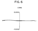
- Fig. 6 shows coma for explaining the imaging performance of the third embodiment.
- Fig. 6 shows coma in the meridional direction at the center of the ring-shaped view field. Note that a solid curve in Fig. 6 represents coma at 248.4 nm, an alternate long and short dashed curve represents coma at 252.4 nm, and an alternate long and two short dashed curve represents coma at 244.4 nm.
- the third embodiment can achieve correction of chromatic aberration within a range of +4 nm at the wavelength of KrF, and maintains an excellent imaging performance.
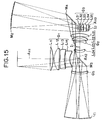
- a light beam from the object surface is incident on a first lens group G1 of positive refractive power.
- the light beam passes through a positive meniscus lens L11 having a concave surface facing the incident side of a light beam, and is then deflected by a planar reflection mirror M3 which is obliquely arranged at 45° with respect to an optical axis Ax1 of the first lens group G1.
- the deflected light beam passes through a biconvex positive lens L12 and a negative meniscus lens L13 having a convex surface facing the incident side of a light beam, and then reaches a first concave reflection mirror M1 having a magnification slightly smaller than unity via a fifth lens group G5 of negative refractive power.
- the fifth lens group G5 comprises a negative meniscus lens having a convex surface facing the first concave reflection mirror side.
- the light beam reflected by the first concave reflection mirror M1 forms a primary image I1 as a reduced image of an object via the fifth lens group G5 again and a second lens group G2 of positive refractive power.
- the second lens group G2 comprises, in succession from the incident side of a light beam, a biconvex positive lens L21, a negative meniscus lens L22 having a concave surface facing the incident side, and a positive meniscus lens L23 having a concave surface facing the incident side.
- the light beam from the primary image I1 is reflected by a second concave reflection mirror M2 having a magnification larger than unity.
- the optical path of the reflected light beam is deflected by a planar reflection mirror M4, and the light beam then reaches a third lens group G3 of positive refractive power.
- the planar reflection mirror M4 is obliquely arranged at 45° with respect to an optical axis Ax3 of the third lens group G3.
- the third lens group G3 comprises, in succession from the incident side of a light beam, a biconvex positive lens L31, a negative meniscus lens L32 having a concave surface facing the incident side, a positive meniscus lens L33 having a convex lens facing the incident side, a biconcave negative lens L34, a positive meniscus lens L35 having a convex surface facing the incident side, a positive meniscus lens L36 having a convex surface facing the incident side, and a positive meniscus lens L37 having a convex surface facing the incident side, and forms a secondary image I2 in a larger reduction scale than that of the primary image I1 at its exit side.
- the positive lens L12 and the negative lens L13 of the first lens group G1 are arranged at only one side so as to allow a light beam toward the first concave reflection mirror to pass therethrough without shielding a light beam in the second lens group G2.
- the second lens group G2 is arranged at only one side so as to guide a light beam from the first concave reflection mirror M1 without shielding a light beam in the first lens group G1.
- the fourth embodiment has a reduction factor of +0.25 or 1/4 as a whole, and achieves a numerical aperture of (N.A.) of 0.30 in a ring-shaped view field centered at an arc having a radius of 20 mm from the optical axis.
- Table 4 below shows data of the fourth embodiment.
- the refractive index of each glass material corresponds to that at the wavelength (248 nm) of KrF.
- Fig. 8 shows coma for explaining the imaging performance of the fourth embodiment.
- Fig. 8 shows coma in the meridional direction at the center of the ring-shaped view field. Note that a solid curve in Fig. 8 represents coma at 248.4 nm, a broken curve represents coma at 238.4 nm, and a dotted curve represents coma at 258.4 nm.
- the fourth embodiment can achieve correction of chromatic aberration within a range of ⁇ 10 nm at the wavelength of KrF, and maintains an excellent imaging performance.
- a second concave reflection mirror M2 comprises a reflection mirror having a non-spherical surface.
- a light beam from the object surface reaches a first concave reflection mirror M1 having a magnification slightly smaller than unity via a first lens group G1 which comprises a positive meniscus lens L11 having a concave surface facing the incident side of a light beam, a positive meniscus lens L12 having a convex surface facing the incident side, a positive meniscus lens L13 having a convex surface facing the incident side, and a positive meniscus lens L14 having a convex surface facing the incident side, and has positive refractive power as a whole, and a fifth lens group G5 of negative refractive power.
- the fifth lens group G5 comprises a negative meniscus lens having a convex surface facing the first concave reflection mirror side.
- the light beam reflected by the first concave reflection mirror M1 is deflected by a planar reflection mirror M3, which is obliquely arranged at 45° with respect to an optical axis Ax1 of the first lens group G1, via the fifth lens group G5 again, and then becomes incident on a second lens group G2 of negative refractive power.
- the second lens group G2 comprises a biconvex positive lens L21, a biconcave negative lens L22, and a positive meniscus lens L23 having a convex surface facing the incident side of a light beam, and forms a primary reduced image I1 at its exit side.
- the light beam from the primary image I1 is deflected by a planar reflection mirror M4 which is obliquely arranged at 45° with respect to an optical axis Ax2 of the second lens group G2, and reaches a second concave reflection mirror M2 having a magnification larger than unity and a non-spherical shape.
- the light beam reflected by the second concave reflection mirror M2 becomes incident on a third lens group G3 of positive refractive power.
- the third lens group G3 comprises a biconvex positive lens L31, a biconcave negative lens L32, a biconvex positive lens L33, a positive meniscus lens L34 having a convex surface facing the incident side of a light beam, a positive meniscus lens L35 having a convex surface facing the incident side, a negative meniscus lens L36 having a convex surface facing the incident side, and a positive meniscus lens L37 having a convex surface facing the incident side, and forms a secondary image I2 in a larger reduction scale than that of the primary image I1.
- the fifth embodiment has a reduction factor of +0.25 or 1/4 as a whole, and achieves a numerical aperture of (N.A.) of 0.5 in a ring-shaped view field centered at an arc having a radius of 24.25 mm from the optical axis.
- Table 5 below shows data of the fifth embodiment.
- the refractive index of each glass material corresponds to that at the wavelength (248 nm) of KrF.
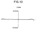
- Fig. 10 shows coma of the fifth embodiment.
- Fig. 10 shows coma in the meridional direction at the center of the ring-shaped view field. As can be seen from Fig. 10, the fifth embodiment maintains an excellent imaging performance.
- each of first and second concave reflection mirrors M1 and M2 has a non-spherical reflection surface.
- a light beam from the object surface passes through a first lens group G1 which comprises a biconvex positive lens L11, a positive meniscus lens L12 having a convex surface facing the incident side of a light beam, a negative meniscus lens L13 having a convex surface facing the incident side, and a negative meniscus lens L14 having a convex surface facing the incident side, and has positive refractive power as a whole, and then reaches a first concave reflection mirror M1 having a magnification slightly smaller than unity via a fifth lens group G5 of negative refractive power.
- the fifth lens group G5 comprises a negative meniscus lens having a convex surface facing the first concave reflection mirror M1 side.
- the light beam reflected by the first concave reflection mirror M1 is deflected by a planar reflection mirror M3, which is obliquely arranged at 45° with respect to an optical axis Ax1 of the first lens group G1, via the fifth lens group G5 again, and becomes incident on a second lens group G2 of negative refractive power.
- the second lens group G2 comprises a negative meniscus lens L21 having a convex surface facing the incident side of a light beam, a biconcave negative lens L22, and a biconvex positive lens L23, and forms a primary image I1 as a reduced image of an object between the negative lens L22 and the positive lens L23.
- the light beam emerging from the second lens group G2 is deflected by a planar reflection mirror M4, which is obliquely arranged at 45° with respect to an optical axis Ax2 of the second lens group G2, and reaches a second concave reflection mirror M2 having a magnification larger than unity.
- the light beam reflected by the second concave reflection mirror M2 is incident on a third lens group G3 of positive refractive power.
- the third lens group G3 comprises, in succession from the incident side of a light beam, a negative meniscus lens L31 having a convex surface facing the object side, a biconvex positive lens L32, a positive meniscus lens L33 having a convex surface facing the incident side, a negative meniscus lens L34 having a concave surface facing the incident side, and a biconvex positive lens L35, and forms a secondary image I2 in a larger reduction scale than that of the primary image I1 at the exit side of the third lens group G3.
- the sixth embodiment has a reduction factor of +0.25 or 1/4 as a whole, and achieves a numerical aperture of (N.A.) of 0.45 in a ring-shaped view field centered at an arc having a radius of 24.25 mm from the optical axis.
- each of the first and second concave reflection mirrors M1 and M2 shown in Table 6 is the radius of paraxial curvature, and the non-spherical surface coefficients of these first and second reflection mirrors M1 and M2 are separately listed.
- the refractive index of each glass material corresponds to that at the wavelength (248 nm) of KrF.
- Fig. 12 shows coma of the sixth embodiment.
- Fig. 12 shows coma in the meridional direction at the center of the ring-shaped view field. As can be seen from Fig. 12, the sixth embodiment maintains an excellent imaging performance.
- a light beam from the object surface emerges from a first lens group G1 which comprises a biconvex positive lens L11, a positive meniscus lens L12 having a convex surface facing the incident side of a light beam, a positive meniscus lens L13 having a convex surface facing the incident side of a light beam, and a negative meniscus lens L14 having a convex surface facing the incident side, and has positive refractive power as a whole, and is deflected by a planar reflection mirror M3 which is obliquely arranged at 45° with respect to an optical axis Ax1 of the first lens group G1.
- the deflected light beam reaches a first concave reflection mirror M1 having a magnification slightly smaller than unity via a fifth lens group G5 of negative refractive power.
- the fifth lens group G5 comprises a negative meniscus lens having a convex surface facing the first concave reflection mirror M1.
- the light beam reflected by the first concave reflection mirror M1 is incident on a second lens group G2 of negative refractive power via the second lens group G5 again.
- the second lens group G2 comprises a negative meniscus lens L21 having a convex surface facing the incident side of a light beam, a biconcave negative lens L22, a positive meniscus lens L23 having a concave surface facing the incident side, and a positive meniscus lens L24 having a concave surface facing the incident side, and forms a primary image I1 as a reduced image of an object in the optical path between the negative lenses L21 and L22.
- the negative lens L21 in the second lens group is arranged at only one side of the optical axis Ax2 so as not to shield the optical path extending from the first lens group G1 toward the first concave reflection mirror M1.
- the light beam emerging from the second lens group G2 is deflected by a planar reflection mirror M4 which is obliquely arranged at 45° with respect to the optical axis Ax2 of the second lens group G2, is reflected by a second concave reflection mirror M2 having a magnification larger than unity, and then becomes incident on a third lens group G3 of positive refractive power.
- the third lens group G3 comprises a negative meniscus lens L31 having a convex surface facing the incident side of a light beam, a biconvex positive lens L32, a positive meniscus lens L33 having a convex surface facing the incident side, a biconcave negative lens L34, and a biconvex positive lens L35, and forms a secondary image I2 in a larger reduction scale than that of the primary image I1.
- the seventh embodiment has a reduction factor of +0.25 or 1/4 as a whole, and achieves a numerical aperture of (N.A.) of 0.4 in a ring-shaped view field centered at an arc having a radius of 25 mm from the optical axis.
- Table 7 below shows data of the seventh embodiment.
- the refractive index of each glass material corresponds to that at the wavelength (193 nm) of ArF.
- Fig. 14 shows coma of the seventh embodiment.
- Fig. 14 shows coma in the meridional direction at the center of the ring-shaped view field. Note that a solid curve in Fig. 14 represents coma at 193.3 nm, a broken curve represents coma at 193.7 nm, and a dotted curve represents coma at 192.9 nm.
- the seventh embodiment can achieve correction of chromatic aberration within a range of ⁇ 0.4 nm at the wavelength of ArF, and maintains an excellent imaging performance.
- a light beam from the object surface passes through a first lens group G1 which comprises a biconvex positive lens L11, a biconvex positive lens L12, a negative meniscus lens L13 having a convex surface facing the incident side of a light beam, and a biconcave negative lens L14, and which has positive refractive power as a whole, and is then deflected by a planar reflection mirror M3 which is obliquely arranged at 45° with respect to an optical axis Ax1 of the first lens group G1.
- the deflected light beam reaches a first concave reflection mirror M1 having a magnification slightly smaller than unity via a fifth lens group G5 of negative refractive power.
- the fifth lens group G5 comprises a negative meniscus lens having a convex surface facing the first concave reflection mirror M1 side.
- the light beam reflected by the first concave reflection mirror M1 is incident on a second lens group G2 of negative refractive power via the fifth lens group G5 again.
- the second lens group G2 comprises a negative meniscus lens L21 having a convex surface facing the incident side of a light beam, a negative meniscus lens L22 having a concave surface facing the incident side, a negative meniscus lens L23 having a concave surface facing the incident side, and a biconvex positive lens L24, and forms a primary reduced image I1 between the negative lenses L21 and L22.
- the light beam emerging from the second lens group G2 is deflected by a planar reflection mirror M4 which is obliquely arranged at 45° with respect to an optical axis Ax2 of the second lens group G2, is reflected by a second concave reflection mirror M2 having a magnification larger than unity, and then becomes incident on a third lens group G3 of positive refractive power.
- the third lens group G3 comprises a negative meniscus lens L31 having a convex surface facing the incident side of a light beam, a biconvex positive lens L32, a biconvex positive lens L33, a negative meniscus lens L34 having a concave surface facing the incident side, and a positive meniscus lens L35 having a convex surface facing the incident side, and forms a secondary image I2 in a larger reduction scale than that of the primary image I1 at its exit side.
- the eighth embodiment has a reduction factor of +0.25 or 1/4 as a whole, and achieves a numerical aperture of (N.A.) of 0.4 in a ring-shaped view field centered at an arc having a radius of 24.25 mm from the optical axis.
- Table 8 below shows data of the eighth embodiment.
- the refractive index of each glass material corresponds to that at the wavelength (248 nm) of KrF.
- Fig. 16 shows coma of the eighth embodiment.
- Fig. 16 shows coma in the meridional direction at the center of the ring-shaped view field. As can be seen from Fig. 16, the eighth embodiment maintains an excellent imaging performance.
- the primary image formed by the first partial optical system (the first lens group G1 and the first concave reflection mirror M1) is a reduced image.
- the primary image formed by the first partial optical system is not limited to a reduced image.
- the optical system is constituted to satisfy the above-mentioned conditions, the optical members constituting the catadioptric reduction projection optical system do not interfere with each other. Therefore, a physically constructible catadioptric reduction projection optical system can be obtained.
- the object surface is set to be parallel to the image surface using the two planar reflection mirrors.
Landscapes
- Physics & Mathematics (AREA)
- General Physics & Mathematics (AREA)
- Optics & Photonics (AREA)
- Lenses (AREA)
Applications Claiming Priority (2)
| Application Number | Priority Date | Filing Date | Title |
|---|---|---|---|
| JP343976/92 | 1992-12-24 | ||
| JP34397692 | 1992-12-24 |
Publications (2)
| Publication Number | Publication Date |
|---|---|
| EP0604093A1 true EP0604093A1 (fr) | 1994-06-29 |
| EP0604093B1 EP0604093B1 (fr) | 1997-11-19 |
Family
ID=18365690
Family Applications (1)
| Application Number | Title | Priority Date | Filing Date |
|---|---|---|---|
| EP19930310039 Expired - Lifetime EP0604093B1 (fr) | 1992-12-24 | 1993-12-13 | Système de projection de réduction catadioptrique |
Country Status (2)
| Country | Link |
|---|---|
| EP (1) | EP0604093B1 (fr) |
| DE (1) | DE69315314T2 (fr) |
Cited By (10)
| Publication number | Priority date | Publication date | Assignee | Title |
|---|---|---|---|---|
| US5583696A (en) * | 1992-12-14 | 1996-12-10 | Canon Kabushiki Kaisha | Reflection and refraction optical system and projection exposure apparatus using the same |
| EP0736789A3 (fr) * | 1995-04-07 | 1997-02-05 | Nippon Kogaku Kk | Système catadioptrique et appareil d'exposition lumineuse utilisante ce système |
| EP0816892A3 (fr) * | 1996-06-14 | 1999-06-09 | Nikon Corporation | Système de lentilles catadioptrique |
| EP0869383A3 (fr) * | 1997-04-01 | 1999-09-08 | Nikon Corporation | Systéme optique catadioptrique |
| US6636350B2 (en) | 2000-01-14 | 2003-10-21 | Carl-Zeiss-Stiftung | Microlithographic reduction projection catadioptric objective |
| EP1079253A4 (fr) * | 1998-04-07 | 2004-09-01 | Nikon Corp | Appareil et procede d'exposition a projection, et systeme optique reflechissant a refraction |
| US7237915B2 (en) | 2000-01-14 | 2007-07-03 | Carl Zeiss Smt Ag | Catadioptric projection system for 157 nm lithography |
| US9726979B2 (en) | 2004-05-17 | 2017-08-08 | Carl Zeiss Smt Gmbh | Catadioptric projection objective with intermediate images |
| US9772478B2 (en) | 2004-01-14 | 2017-09-26 | Carl Zeiss Smt Gmbh | Catadioptric projection objective with parallel, offset optical axes |
| CN112910555A (zh) * | 2021-01-20 | 2021-06-04 | 中国科学技术大学 | 面向收发端小型化的可见光通信凹凸透镜天线及其设计方法 |
Families Citing this family (2)
| Publication number | Priority date | Publication date | Assignee | Title |
|---|---|---|---|---|
| US6995930B2 (en) | 1999-12-29 | 2006-02-07 | Carl Zeiss Smt Ag | Catadioptric projection objective with geometric beam splitting |
| US8208198B2 (en) | 2004-01-14 | 2012-06-26 | Carl Zeiss Smt Gmbh | Catadioptric projection objective |
Citations (5)
| Publication number | Priority date | Publication date | Assignee | Title |
|---|---|---|---|---|
| US4685777A (en) * | 1984-12-27 | 1987-08-11 | Canon Kabushiki Kaisha | Reflection and refraction optical system |
| EP0271737A2 (fr) * | 1986-12-17 | 1988-06-22 | Svg Lithography Systems, Inc. | Système optique de retransmission avec amplification |
| US4812028A (en) * | 1984-07-23 | 1989-03-14 | Nikon Corporation | Reflection type reduction projection optical system |
| EP0350955A2 (fr) * | 1988-07-15 | 1990-01-17 | Svg Lithography Systems, Inc. | Dispositif optique de réduction |
| EP0527043A1 (fr) * | 1991-08-05 | 1993-02-10 | Nikon Corporation | Système de projection en réduction catadioptrique |
-
1993
- 1993-12-13 EP EP19930310039 patent/EP0604093B1/fr not_active Expired - Lifetime
- 1993-12-13 DE DE69315314T patent/DE69315314T2/de not_active Expired - Lifetime
Patent Citations (5)
| Publication number | Priority date | Publication date | Assignee | Title |
|---|---|---|---|---|
| US4812028A (en) * | 1984-07-23 | 1989-03-14 | Nikon Corporation | Reflection type reduction projection optical system |
| US4685777A (en) * | 1984-12-27 | 1987-08-11 | Canon Kabushiki Kaisha | Reflection and refraction optical system |
| EP0271737A2 (fr) * | 1986-12-17 | 1988-06-22 | Svg Lithography Systems, Inc. | Système optique de retransmission avec amplification |
| EP0350955A2 (fr) * | 1988-07-15 | 1990-01-17 | Svg Lithography Systems, Inc. | Dispositif optique de réduction |
| EP0527043A1 (fr) * | 1991-08-05 | 1993-02-10 | Nikon Corporation | Système de projection en réduction catadioptrique |
Cited By (14)
| Publication number | Priority date | Publication date | Assignee | Title |
|---|---|---|---|---|
| US5583696A (en) * | 1992-12-14 | 1996-12-10 | Canon Kabushiki Kaisha | Reflection and refraction optical system and projection exposure apparatus using the same |
| EP0736789A3 (fr) * | 1995-04-07 | 1997-02-05 | Nippon Kogaku Kk | Système catadioptrique et appareil d'exposition lumineuse utilisante ce système |
| US5689377A (en) * | 1995-04-07 | 1997-11-18 | Nikon Corporation | Catadioptric optical system and exposure apparatus having the same |
| EP0816892A3 (fr) * | 1996-06-14 | 1999-06-09 | Nikon Corporation | Système de lentilles catadioptrique |
| EP0869383A3 (fr) * | 1997-04-01 | 1999-09-08 | Nikon Corporation | Systéme optique catadioptrique |
| EP1079253A4 (fr) * | 1998-04-07 | 2004-09-01 | Nikon Corp | Appareil et procede d'exposition a projection, et systeme optique reflechissant a refraction |
| US6636350B2 (en) | 2000-01-14 | 2003-10-21 | Carl-Zeiss-Stiftung | Microlithographic reduction projection catadioptric objective |
| US6873476B2 (en) | 2000-01-14 | 2005-03-29 | Carl-Zeiss-Stiftung | Microlithographic reduction projection catadioptric objective |
| US7218445B2 (en) | 2000-01-14 | 2007-05-15 | Carl-Zeiss Stiftung | Microlithographic reduction projection catadioptric objective |
| US7237915B2 (en) | 2000-01-14 | 2007-07-03 | Carl Zeiss Smt Ag | Catadioptric projection system for 157 nm lithography |
| US7508581B2 (en) | 2000-01-14 | 2009-03-24 | Carl Zeiss Smt Ag | Catadioptric projection system for 157 nm lithography |
| US9772478B2 (en) | 2004-01-14 | 2017-09-26 | Carl Zeiss Smt Gmbh | Catadioptric projection objective with parallel, offset optical axes |
| US9726979B2 (en) | 2004-05-17 | 2017-08-08 | Carl Zeiss Smt Gmbh | Catadioptric projection objective with intermediate images |
| CN112910555A (zh) * | 2021-01-20 | 2021-06-04 | 中国科学技术大学 | 面向收发端小型化的可见光通信凹凸透镜天线及其设计方法 |
Also Published As
| Publication number | Publication date |
|---|---|
| EP0604093B1 (fr) | 1997-11-19 |
| DE69315314D1 (de) | 1998-01-02 |
| DE69315314T2 (de) | 1998-03-19 |
Similar Documents
| Publication | Publication Date | Title |
|---|---|---|
| JP3747958B2 (ja) | 反射屈折光学系 | |
| USRE38421E1 (en) | Exposure apparatus having catadioptric projection optical system | |
| EP1318425B1 (fr) | Système optique catadioptrique et dispositif d'exposition muni d'un tel système | |
| US5071240A (en) | Reflecting optical imaging apparatus using spherical reflectors and producing an intermediate image | |
| US6392822B1 (en) | Dual-imaging optical system | |
| JP3747951B2 (ja) | 反射屈折光学系 | |
| USRE37846E1 (en) | Projection optical system and exposure apparatus using the same | |
| US5668673A (en) | Catadioptric reduction projection optical system | |
| EP0770895A2 (fr) | Système de projection optique avec appareil d'exposition | |
| US6560031B1 (en) | Optical projection lens system | |
| KR20000011933A (ko) | 카타다이옵트릭광학시스템및그를구비한노광장치 | |
| EP0732605A2 (fr) | Appareil d'exposition | |
| JPH07111512B2 (ja) | 補償型光学システム | |
| JP2001185480A (ja) | 投影光学系及び該光学系を備える投影露光装置 | |
| EP0604093A1 (fr) | Système de projection de réduction catadioptrique | |
| JPH1195095A (ja) | 投影光学系 | |
| US7317571B2 (en) | Catadioptric projection optical system, exposure apparatus having the same, device fabrication method | |
| JPH07128592A (ja) | 縮小投影レンズ | |
| US20020167650A1 (en) | Projection optical system and exposure apparatus with the same | |
| JP2009145724A (ja) | 投影光学系及びそれを有する露光装置 | |
| EP0581585B1 (fr) | Système de projection en réduction catadioptrique | |
| EP0527043B1 (fr) | Système de projection en réduction catadioptrique | |
| JPH0525086B2 (fr) | ||
| JP3781044B2 (ja) | 反射屈折光学系および投影露光装置 | |
| JP2006078631A (ja) | 投影光学系及びそれを有する露光装置 |
Legal Events
| Date | Code | Title | Description |
|---|---|---|---|
| PUAI | Public reference made under article 153(3) epc to a published international application that has entered the european phase |
Free format text: ORIGINAL CODE: 0009012 |
|
| AK | Designated contracting states |
Kind code of ref document: A1 Designated state(s): DE FR GB |
|
| 17P | Request for examination filed |
Effective date: 19941129 |
|
| 17Q | First examination report despatched |
Effective date: 19960826 |
|
| GRAG | Despatch of communication of intention to grant |
Free format text: ORIGINAL CODE: EPIDOS AGRA |
|
| GRAH | Despatch of communication of intention to grant a patent |
Free format text: ORIGINAL CODE: EPIDOS IGRA |
|
| GRAH | Despatch of communication of intention to grant a patent |
Free format text: ORIGINAL CODE: EPIDOS IGRA |
|
| GRAA | (expected) grant |
Free format text: ORIGINAL CODE: 0009210 |
|
| AK | Designated contracting states |
Kind code of ref document: B1 Designated state(s): DE FR GB |
|
| REF | Corresponds to: |
Ref document number: 69315314 Country of ref document: DE Date of ref document: 19980102 |
|
| ET | Fr: translation filed | ||
| PLBE | No opposition filed within time limit |
Free format text: ORIGINAL CODE: 0009261 |
|
| STAA | Information on the status of an ep patent application or granted ep patent |
Free format text: STATUS: NO OPPOSITION FILED WITHIN TIME LIMIT |
|
| 26N | No opposition filed | ||
| REG | Reference to a national code |
Ref country code: GB Ref legal event code: IF02 |
|
| PGFP | Annual fee paid to national office [announced via postgrant information from national office to epo] |
Ref country code: DE Payment date: 20121205 Year of fee payment: 20 |
|
| PGFP | Annual fee paid to national office [announced via postgrant information from national office to epo] |
Ref country code: GB Payment date: 20121212 Year of fee payment: 20 |
|
| PGFP | Annual fee paid to national office [announced via postgrant information from national office to epo] |
Ref country code: FR Payment date: 20130107 Year of fee payment: 20 |
|
| REG | Reference to a national code |
Ref country code: DE Ref legal event code: R071 Ref document number: 69315314 Country of ref document: DE |
|
| REG | Reference to a national code |
Ref country code: GB Ref legal event code: PE20 Expiry date: 20131212 |
|
| PG25 | Lapsed in a contracting state [announced via postgrant information from national office to epo] |
Ref country code: GB Free format text: LAPSE BECAUSE OF EXPIRATION OF PROTECTION Effective date: 20131212 Ref country code: DE Free format text: LAPSE BECAUSE OF EXPIRATION OF PROTECTION Effective date: 20131214 |