EP0604119B1 - Tintenkassette mit zusammendrückbarem Tintenbehälter - Google Patents
Tintenkassette mit zusammendrückbarem Tintenbehälter Download PDFInfo
- Publication number
- EP0604119B1 EP0604119B1 EP93310156A EP93310156A EP0604119B1 EP 0604119 B1 EP0604119 B1 EP 0604119B1 EP 93310156 A EP93310156 A EP 93310156A EP 93310156 A EP93310156 A EP 93310156A EP 0604119 B1 EP0604119 B1 EP 0604119B1
- Authority
- EP
- European Patent Office
- Prior art keywords
- ink
- bag
- flexible
- reservoir
- plate
- Prior art date
- Legal status (The legal status is an assumption and is not a legal conclusion. Google has not performed a legal analysis and makes no representation as to the accuracy of the status listed.)
- Expired - Lifetime
Links
- 238000000034 method Methods 0.000 claims description 7
- 230000002093 peripheral effect Effects 0.000 claims description 7
- 230000001681 protective effect Effects 0.000 claims description 5
- 239000000463 material Substances 0.000 claims description 4
- 239000007788 liquid Substances 0.000 claims description 2
- 239000012528 membrane Substances 0.000 description 20
- 229920003023 plastic Polymers 0.000 description 11
- 239000004033 plastic Substances 0.000 description 11
- 239000010410 layer Substances 0.000 description 9
- 239000002184 metal Substances 0.000 description 6
- 239000006260 foam Substances 0.000 description 5
- 239000012530 fluid Substances 0.000 description 3
- 239000000853 adhesive Substances 0.000 description 2
- 230000001070 adhesive effect Effects 0.000 description 2
- 238000004891 communication Methods 0.000 description 2
- 238000010276 construction Methods 0.000 description 2
- 229920002457 flexible plastic Polymers 0.000 description 2
- 230000005012 migration Effects 0.000 description 2
- 238000013508 migration Methods 0.000 description 2
- 238000012986 modification Methods 0.000 description 2
- 230000004048 modification Effects 0.000 description 2
- -1 polypropylene Polymers 0.000 description 2
- 238000007639 printing Methods 0.000 description 2
- 210000004894 snout Anatomy 0.000 description 2
- 229910001220 stainless steel Inorganic materials 0.000 description 2
- 239000010935 stainless steel Substances 0.000 description 2
- 238000003466 welding Methods 0.000 description 2
- 206010013642 Drooling Diseases 0.000 description 1
- 239000004698 Polyethylene Substances 0.000 description 1
- 239000004743 Polypropylene Substances 0.000 description 1
- 208000008630 Sialorrhea Diseases 0.000 description 1
- 239000003522 acrylic cement Substances 0.000 description 1
- 230000009471 action Effects 0.000 description 1
- 230000002411 adverse Effects 0.000 description 1
- 238000011161 development Methods 0.000 description 1
- 230000018109 developmental process Effects 0.000 description 1
- 238000005516 engineering process Methods 0.000 description 1
- 230000007613 environmental effect Effects 0.000 description 1
- 230000004927 fusion Effects 0.000 description 1
- 238000001746 injection moulding Methods 0.000 description 1
- 238000009434 installation Methods 0.000 description 1
- 238000002844 melting Methods 0.000 description 1
- 230000008018 melting Effects 0.000 description 1
- 238000004806 packaging method and process Methods 0.000 description 1
- 229920000573 polyethylene Polymers 0.000 description 1
- 229920000642 polymer Polymers 0.000 description 1
- 229920001155 polypropylene Polymers 0.000 description 1
- 239000011241 protective layer Substances 0.000 description 1
- 230000009467 reduction Effects 0.000 description 1
- 230000004044 response Effects 0.000 description 1
- 230000035939 shock Effects 0.000 description 1
- 239000000126 substance Substances 0.000 description 1
- 230000008719 thickening Effects 0.000 description 1
Images

Classifications
-
- B—PERFORMING OPERATIONS; TRANSPORTING
- B41—PRINTING; LINING MACHINES; TYPEWRITERS; STAMPS
- B41J—TYPEWRITERS; SELECTIVE PRINTING MECHANISMS, i.e. MECHANISMS PRINTING OTHERWISE THAN FROM A FORME; CORRECTION OF TYPOGRAPHICAL ERRORS
- B41J2/00—Typewriters or selective printing mechanisms characterised by the printing or marking process for which they are designed
- B41J2/005—Typewriters or selective printing mechanisms characterised by the printing or marking process for which they are designed characterised by bringing liquid or particles selectively into contact with a printing material
- B41J2/01—Ink jet
- B41J2/17—Ink jet characterised by ink handling
- B41J2/175—Ink supply systems ; Circuit parts therefor
- B41J2/17503—Ink cartridges
- B41J2/17513—Inner structure
-
- B—PERFORMING OPERATIONS; TRANSPORTING
- B41—PRINTING; LINING MACHINES; TYPEWRITERS; STAMPS
- B41J—TYPEWRITERS; SELECTIVE PRINTING MECHANISMS, i.e. MECHANISMS PRINTING OTHERWISE THAN FROM A FORME; CORRECTION OF TYPOGRAPHICAL ERRORS
- B41J2/00—Typewriters or selective printing mechanisms characterised by the printing or marking process for which they are designed
- B41J2/005—Typewriters or selective printing mechanisms characterised by the printing or marking process for which they are designed characterised by bringing liquid or particles selectively into contact with a printing material
- B41J2/01—Ink jet
- B41J2/17—Ink jet characterised by ink handling
- B41J2/175—Ink supply systems ; Circuit parts therefor
- B41J2/17503—Ink cartridges
- B41J2/17513—Inner structure
- B41J2002/17516—Inner structure comprising a collapsible ink holder, e.g. a flexible bag
Definitions
- the present invention relates generally to ink reservoirs for high speed computer driven inkjet printers and plotters and other applications where precise pattern dispensation of a fluid is required such as in the layout of circuit masks.
- the ink reservoir is ordinarily maintained under a sub-atmospheric or negative pressure so that ink will not leak or drool from the print head.
- Various types of ink reservoirs may be used including refillable ink reservoir cartridges which are mounted on the moveable printer carriage, throwaway replaceable cartridges which are mounted on the printer carriage and remote or offboard ink reservoirs from which ink is brought to the print head on the printer carriage by tubing.
- a polymer foam is ordinarily provided in the ink reservoir so that the capillary action of the foam will prevent ink from drooling from the print head.
- Polymeric foams of the type typically used for this purpose are non-biodegradable and thus cause environmental problems whenever a previously used cartridge is emptied and thrown away.
- the use of industrial foam in the ink reservoir restricts the operating pressure range of the ink cartridge and such foams ordinarily leave a chemical residue which is incompatible with and/or reacts adversely with printer ink.
- the relatively long tubing used to convey ink from an offboard pressure reservoir to a printing head is not easily adaptable to deliver ink to the print head at different printing pressure ranges.
- a collapsible ink reservoir for a handheld inkjet printer is disclosed in U.S. Patent No. 4,422,084 issued Dec. 20, 1983 to Saito.
- Negative pressure is maintained in a polypropylene ink bag by various types of springs which bias the bag walls apart from each other.
- the springs may be mounted inside of or externally of the ink bag but the spring pressure regulator construction does not result in substantially complete emptying of the ink bag and the bag itself is not carried on a printer carriage.
- the cartridge disclosed in that application basically comprises a rectangular housing containing a flexible bag of ink, an ink filter and a print head which receives ink from the filter.
- a spring inside of the bag of ink urges its flexible walls apart from each other thus maintaining a negative or sub-atmospheric pressure in the reservoir which is overcome as ink is emitted from the printhead.
- the spring essentially consists of a pair of spaced parallel plates which are urged apart by a spring.
- EP-A-0,437,363 discloses a pressure-sensitive accumulator for ink-jet pens which is operative to regulate changes in the back pressure of an ink-jet pen reservoir so that ink does not leak from the pen print head and so that the print head is able to completely empty the reservoir of ink.
- the accumulator includes a flexible bag that is mounted to a flat curved spring. The elasticity of the spring tends to contract the bag as the bag expands in response to back pressure reduction in the reservoir.
- the present invention provides a collapsible ink reservoir to be maintained under negative pressure in a liquid ink cartridge, said ink reservoir comprising:
- the present invention further provides a thermal ink jet printer cartridge comprising: a rigid housing containing an ink reservoir to be maintained under negative pressure, said reservoir comprising:
- the invention provides a method of providing a securely positioned spring member inside an ink-jet print cartridge reservoir having flexible film walls, comprising the steps of:
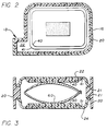
- the drawing shows a replaceable ink cartridge comprising a rigid outer housing 10 having a pair of spaced cover plates 12,14 intended to be affixed as by heat bonding, or adhesive, or preferably press fit through interlocking tabs to opposite sides of a plastic peripheral wall section 16.
- Snout portion 13 of the cartridge has an ink discharge aperture in its lowermost end wall (as seen in Fig. 1) to which is affixed an electrically driven print head, not shown.
- An inner collapsible reservoir structure unit 5 comprised of a relatively rigid inner plastic frame 20 and a pair of ink bag sidewalls 22, 24, at least one of which is flexible membrane such as plastic, attached thereto is mounted in the outer housing 10.
- inner frame 20 is molded with the outer housing 10 in a two step injection molding process.
- Inner frame 20 is formed of a softer and lower melting point plastic than the plastic of housing 10 to permit heat bonding of the bag walls 22, 24 thereto.
- inner frame 20 may be separately constructed with some flexibility to assist in mounting it in the housing 10 but the frame 20 is rigid relative to the flexible ink bag membranes described below.
- the frame 20 has a pair of opposite side edges 21 to which the flexible plastic ink bag membranes 22, 24 are respectively joined as by heat welding at their peripheral edges to form the reservoir structure 25.
- the reservoir structure 25 contains a pressure regulator 30 which in turn is preferably comprised of a pair of spaced substantially parallel metal sideplates 40, 50 urged apart by a bow spring 60 toward the flexible membranes 22, 24.
- the assembled reservoir structure including the inner frame 20, membranes 22, 24 and pressure regulator 30 is then mounted inside of wall section 16 of the cartridge and side walls 12, 14 are then affixed to the cartridge housing peripheral wall 16.
- the snout portion 13 of housing 10 also contains an ink filter 18 which is placed in fluid communication with the flexible ink bag reservoir.
- the filter 18 may be mounted inside the reservoir structure or it can be positioned outside of the reservoir structure but inside outer housing 10 with minor porting and seal modifications to ensure fluid communication from the ink reservoir to the filter 18.
- the lowermost portion of the peripheral outer housing wall 16 (as viewed in Fig.1) is provided with an ink discharge aperture 19 through which ink is downwardly discharged from the filter 18 to the print head, not shown.
- the pressure regulator sideplates 40,50 may be substantially parallel and individually cut from a continuous metal strip of metal such as stainless steel, each plate being of generally rectangular configuration with rounded corners to minimize damaging the flexible bag membranes.
- the bow spring 60 also may conveniently be cut from a common strip of metal such as stainless steel.
- the bow spring 60 is affixed, preferably by spot or laser welding at the apexes of each of its bights centrally onto each of the sideplates 40,50.
- edge guard is bonded to the outer surface of the respective side plates.
- the edge guards comprise a film of plastic material adhesively bonded to the sideplates.
- the edge guard is in the form of a thin but tough polyethylene cover layer 41,51 having an acrylic adhesive on one surface thereof may then be press bonded to the outer surface of each side plate 40,50 if desired.
- the films of plastic material can then be heat bonded to the plastic sidewall.
- the cover layers 41,51 are each sized slightly larger than the side plates 40,50 so that a marginal width of approximately 1.2 millimeters of the cover layers extends beyond each edge of the metal plates 40,50 to prevent those edges from contacting the comparatively delicate plastic bag wall membranes 22,24.
- the pressure regulator 30 is centrally positioned in the frame 20 and housing 10 and the two flexible plastic ink bag sidewalls or membranes 22,24 are then heat bonded or cemented at their peripheral edges to the edge wall 21 of the inner plastic frame 20, care being taken to maintain the central positioning at all times of the regulator and cover layers 41,51 in the frame 20 between the flexible membrane walls 22,24.
- the bag walls 22,24 are then securely affixed to the pressure regulator 30, preferably by heat bonding the membrane bag walls 22, 24 to the cover layers 41, 51 in the area bounded by the broken line B.
- This heat bonding has the primary purpose of preventing relative motion between the pressure regulator 30 and preventing direct contact of the metal sideplates 40, 50 with the relatively delicate membrane bag walls 22, 24 to prevent the edges of the sideplates from cutting or puncturing the membranes.
- the bag walls may be directly bonded by heat bonding or suitable adhesive to the pressure regulator. Either method of construction also reduces the area of ink contact with the membrane walls 22, 24 which in turn minimizes the migration of moisture from the ink through the membranes. Such migration, over time, degrades the ink quality and this problem is thus minimized.
- the dimensions of the dashed line area of heat bonding are approximately 8 mm by 29 mm. and the heat bond area is centrally located on the sideplates 40, 50.
- the regulator side plates and bag sidewalls are initially assembled to be in moveable contact with each other. Thereafter, a heated platen momentarily contacts the film and fuses the film to the plate. A slight vacuum must be applied to the inside of the frame to improve the quality of the fusion.
- cover layers 41, 51 may in some instances be unnecessary and an ink bag having a single flexible membrane wall instead of two flexible membrane walls might be constructed.
- the pressure regulator need only have a single side plate urged into engagement by a spring with the single flexible membrane bag wall.
- the invention provides a bonding technique to assure that the regulator is centrally positioned and always held in its proper place between the flexible membrane bag walls, preferably by heat bonding of the bag walls to an edge guard layer covering the outer surface of the two side plates 40, 50.
- a protective edge guard in the form of a layer of tough plastic bonded to the outer surface of the side plates, the protective layers each having a peripheral edge which extends beyond the edge of the side plate to prevent the edges of the side plates from directly contacting the bag walls.
Landscapes
- Ink Jet (AREA)
Claims (10)
- Ein zusammenklappbarer Tintenbehälter (5), der in einer Flüssigtintenkassette unter negativem Druck gehalten werden soll, wobei der Tintenbehälter folgende Merkmale aufweist:a) ein Paar von Tintentaschenseitenwänden (22, 24), die beide an ihrem Umfang verbunden sind, um eine Tintentasche zu bilden, wobei mindestens eine der Seitenwände flexibel ist;b) einen Druckregler (30) in der Tasche, der mindestens eine Seitenplatte (40, 50) und eine Feder (60) aufweist, die die Seitenplatte zu der flexiblen Tintentaschenseitenwand hin drängt; undc) eine Verbindungseinrichtung, die die Seitenplatte an der flexiblen Tintentaschenseitenwand befestigt, um die Position des Reglers in der Tasche beizubehalten.
- Der Tintenbehälter gemäß Anspruch 1, bei dem die Verbindungseinrichtung ferner eine schützende Kantenschutzvorrichtung (41, 51) aufweist, die an der Seitenplatte (40, 50) befestigt ist, um einen direkten Kontakt der Kanten der Seitenplatte mit der flexiblen Taschenseitenwand zu verhindern.
- Der Tintenbehälter gemäß Anspruch 2, bei dem die Tasche ein Paar beabstandeter flexibler Seitenwände (22, 24) aufweist, wobei der Druckregler ein Paar beabstandeter Seitenplatten (40, 50) aufweist, welche durch die Feder voneinander weggedrängt werden, wobei jede Seitenplatte eine schützende Kantenschutzvorrichtung (41, 51) aufweist, die an derselben befestigt ist.
- Der Tintenbehälter gemäß einem beliebigen der vorhergehenden Ansprüche, der ferner einen Umfangsrahmen (20) aufweist, welcher im Vergleich zu den flexiblen Tintentaschenseitenwänden (22, 24) relativ starr ist, wobei die Seitenwände beide an ihrem Umfang mit dem Rahmen verbunden sind.
- Der Tintenbehälter gemäß einem beliebigen der vorhergehenden Ansprüche, bei dem die Platten oder Platten (40, 50) jeweils mit den Seitenwänden (22, 24) hitzeverbunden sind.
- Der Tintenbehälter gemäß einem beliebigen der vorhergehenden Ansprüche, bei dem die Taschenseitenwand (22, 24) direkt an der Seitenplatte befestigt ist.
- Eine Kassette für einen thermischen Tintenstrahldrucker mit einem starren Gehäuse (10), das einen Tintenbehälter (5) gemäß einem beliebigen der vorhergehenden Ansprüche enthält, welcher unter negativem Druck gehalten werden soll.
- Ein Verfahren zum Schaffen eines fest positionierten Federbauglieds (60) innerhalb eines Tintenstrahldruckkassettenbehälters (5) mit flexiblen Folienwänden (22, 24) mit folgenden Schritten: Positionieren einer Platte (40, 50) zwischen das Federbauglied (60) und die Folienwände (22, 24); Definieren einer vorbestimmten Verbindungsfläche (B) in einer mittleren Position der Platte (40, 50); und Verbinden einer äußeren Oberfläche der Platte mit einer inneren Oberfläche der Folienwände in dem vorbestimmten Verbindungsbereich.
- Das Verfahren gemäß Anspruch 8, bei dem der Verbindungsschritt die Verwendung einer Zwischenschicht (41, 51) aus einem Material zwischen der Platte und den Folienwänden aufweist, um die Verbindung zu erleichtern.
- Das Verfahren gemäß Anspruch 9, welches ferner das Erstrecken der Zwischenschicht aus einem Material über den Umfang der Platte hinaus aufweist, um zu verhindern, daß die Platte die Folienwände durchstößt.
Applications Claiming Priority (2)
| Application Number | Priority Date | Filing Date | Title |
|---|---|---|---|
| US997257 | 1992-12-23 | ||
| US07/997,257 US5440333A (en) | 1992-12-23 | 1992-12-23 | Collapsible ink reservoir and ink-jet cartridge with protective bonding layer for the pressure regulator |
Publications (3)
| Publication Number | Publication Date |
|---|---|
| EP0604119A2 EP0604119A2 (de) | 1994-06-29 |
| EP0604119A3 EP0604119A3 (en) | 1994-09-07 |
| EP0604119B1 true EP0604119B1 (de) | 1996-09-11 |
Family
ID=25543802
Family Applications (1)
| Application Number | Title | Priority Date | Filing Date |
|---|---|---|---|
| EP93310156A Expired - Lifetime EP0604119B1 (de) | 1992-12-23 | 1993-12-16 | Tintenkassette mit zusammendrückbarem Tintenbehälter |
Country Status (4)
| Country | Link |
|---|---|
| US (1) | US5440333A (de) |
| EP (1) | EP0604119B1 (de) |
| JP (1) | JPH06226993A (de) |
| DE (1) | DE69304670T2 (de) |
Families Citing this family (41)
| Publication number | Priority date | Publication date | Assignee | Title |
|---|---|---|---|---|
| US5574490A (en) * | 1992-08-12 | 1996-11-12 | Hewlett-Packard Company | Ink jet hard copy apparatus ink cartridge |
| US5691755A (en) * | 1994-04-18 | 1997-11-25 | Hewlett-Packard Company | Collapsible ink cartridge |
| US5637166A (en) * | 1994-10-04 | 1997-06-10 | Hewlett-Packard Company | Similar material thermal tab attachment process for ink-jet pen |
| US5751323A (en) * | 1994-10-04 | 1998-05-12 | Hewlett-Packard Company | Adhesiveless printhead attachment for ink-jet pen |
| US5686949A (en) * | 1994-10-04 | 1997-11-11 | Hewlett-Packard Company | Compliant headland design for thermal ink-jet pen |
| US5896153A (en) * | 1994-10-04 | 1999-04-20 | Hewlett-Packard Company | Leak resistant two-material frame for ink-jet print cartridge |
| US5538586A (en) * | 1994-10-04 | 1996-07-23 | Hewlett-Packard Company | Adhesiveless encapsulation of tab circuit traces for ink-jet pen |
| US5659345A (en) * | 1994-10-31 | 1997-08-19 | Hewlett-Packard Company | Ink-jet pen with one-piece pen body |
| DE69514074T2 (de) * | 1994-10-31 | 2000-04-20 | Hewlett-Packard Co. | Tintenbehälter mit ungefähr gleichgrossem porösen Körper |
| JP3374209B2 (ja) | 1994-11-18 | 2003-02-04 | セイコーエプソン株式会社 | インクジェットプリンタ用インク供給装置 |
| JP3251845B2 (ja) | 1995-04-17 | 2002-01-28 | キヤノン株式会社 | 負圧を与える液体収納容器、該容器の製造方法、該容器とインクジェット記録ヘッドとを一体化したインクジェットカートリッジ及びインクジェット記録装置 |
| JP3245082B2 (ja) * | 1996-02-23 | 2002-01-07 | キヤノン株式会社 | 液体収納容器、該容器の製造方法、該容器を用いるインクジェットカートリッジ及びインクジェット記録装置 |
| JP3245088B2 (ja) | 1996-07-01 | 2002-01-07 | キヤノン株式会社 | 液体吐出ヘッドカートリッジ及び該カートリッジに用いられる液体収容容器 |
| US6305794B1 (en) | 1996-08-02 | 2001-10-23 | Canon Kabushiki Kaisha | Liquid container, ink jet cartridge having same and manufacturing method of the container |
| JP3245092B2 (ja) | 1996-09-11 | 2002-01-07 | キヤノン株式会社 | 液体注入方法 |
| KR100209515B1 (ko) * | 1997-02-05 | 1999-07-15 | 윤종용 | 자성잉크를 이용한 잉크젯 프린터의 분사 장치 및 방법 |
| KR100209516B1 (ko) * | 1997-02-05 | 1999-07-15 | 윤종용 | 잉크젯 프린트 헤드의 잉크 저장 장치 및 방법 |
| JP3952550B2 (ja) * | 1997-08-22 | 2007-08-01 | ブラザー工業株式会社 | インクカートリッジ及びそれを用いたインクジェット記録装置 |
| JPH11240171A (ja) | 1997-12-22 | 1999-09-07 | Oki Data Corp | インク貯蔵容器 |
| US6250751B1 (en) | 2000-03-28 | 2001-06-26 | Lexmark International, Inc. | Ink jet printer cartridge manufacturing method and apparatus |
| US6557990B2 (en) | 2001-04-26 | 2003-05-06 | Hewlett-Packard Development Company | Evacuated structures for removing accumulated air |
| US6481837B1 (en) | 2001-08-01 | 2002-11-19 | Benjamin Alan Askren | Ink delivery system |
| US6959984B2 (en) | 2001-08-14 | 2005-11-01 | Canon Kabushiki Kaisha | Liquid container and inkjet cartridge |
| JP2003191488A (ja) * | 2001-12-27 | 2003-07-08 | Canon Inc | 液体収納容器、インクジェットカートリッジおよびインクジェット記録装置 |
| US6883907B2 (en) * | 2002-10-24 | 2005-04-26 | Hewlett-Packard Development Company, L.P. | Ink cartridge and expansible bladder for an ink cartridge |
| US6817707B1 (en) | 2003-06-18 | 2004-11-16 | Lexmark International, Inc. | Pressure controlled ink jet printhead assembly |
| US6776478B1 (en) | 2003-06-18 | 2004-08-17 | Lexmark International, Inc. | Ink source regulator for an inkjet printer |
| US20040257412A1 (en) * | 2003-06-18 | 2004-12-23 | Anderson James D. | Sealed fluidic interfaces for an ink source regulator for an inkjet printer |
| US6796644B1 (en) | 2003-06-18 | 2004-09-28 | Lexmark International, Inc. | Ink source regulator for an inkjet printer |
| US6786580B1 (en) | 2003-06-18 | 2004-09-07 | Lexmark International, Inc. | Submersible ink source regulator for an inkjet printer |
| US6837577B1 (en) * | 2003-06-18 | 2005-01-04 | Lexmark International, Inc. | Ink source regulator for an inkjet printer |
| US7147314B2 (en) * | 2003-06-18 | 2006-12-12 | Lexmark International, Inc. | Single piece filtration for an ink jet print head |
| CN100400295C (zh) * | 2004-12-07 | 2008-07-09 | 佳能株式会社 | 液体容器及其制造方法 |
| US7954662B2 (en) * | 2005-12-28 | 2011-06-07 | Canon Kabushiki Kaisha | Liquid storage container |
| JP5106134B2 (ja) * | 2008-01-10 | 2012-12-26 | キヤノン株式会社 | 液体収納容器 |
| US8272704B2 (en) | 2008-05-22 | 2012-09-25 | Zipher Limited | Ink containment system and ink level sensing system for an inkjet cartridge |
| US8091993B2 (en) * | 2008-05-22 | 2012-01-10 | Videojet Technologies Inc. | Ink containment system and ink level sensing system for an inkjet cartridge |
| USD823941S1 (en) | 2016-03-22 | 2018-07-24 | Dataprint Technology, Inc. | Postage meter printer module |
| US9427973B1 (en) * | 2016-03-22 | 2016-08-30 | Dataprint Technology, Inc. | Postage meter printer module and housing therefor |
| CN107953674B (zh) * | 2016-10-17 | 2020-11-06 | 精工爱普生株式会社 | 液体容纳体 |
| US20250381781A1 (en) * | 2024-06-12 | 2025-12-18 | Sakura Finetek U.S.A., Inc. | Inkjet cartridges |
Family Cites Families (8)
| Publication number | Priority date | Publication date | Assignee | Title |
|---|---|---|---|---|
| US3708798A (en) * | 1971-12-23 | 1973-01-02 | Ibm | Ink distribution for non-impact printing recorder |
| FR2640018A1 (fr) * | 1988-11-08 | 1990-06-08 | Olaer Ind Sa | Separateur souple composite pour reservoir de pression, son procede de realisation, et reservoir de pression comportant un tel separateur souple |
| CA2019290A1 (en) * | 1990-01-12 | 1991-07-12 | Bruce Cowger | Pressure-sensitive accumulator for ink-jet pens |
| JP3115660B2 (ja) * | 1990-12-07 | 2000-12-11 | キヤノン株式会社 | 分解性プラスチックを構成の一部に用いたインクジェットヘッドカートリッジ、インクタンクカートリッジおよびこれらカートリッジ類が装着される装着部を有したインクジェット装置 |
| US5359353A (en) * | 1991-06-19 | 1994-10-25 | Hewlett-Packard Company | Spring-bag printer ink cartridge with volume indicator |
| US5280300A (en) * | 1991-08-27 | 1994-01-18 | Hewlett-Packard Company | Method and apparatus for replenishing an ink cartridge |
| CA2093981C (en) * | 1992-08-12 | 2001-03-20 | George T. Kaplinsky | Collapsible ink reservoir structure and printer ink cartridge |
| CA2093971A1 (en) * | 1992-08-12 | 1994-02-13 | Tofigh Khodapanah | Ink pressure regulator for a thermal ink jet printer |
-
1992
- 1992-12-23 US US07/997,257 patent/US5440333A/en not_active Expired - Lifetime
-
1993
- 1993-12-16 DE DE69304670T patent/DE69304670T2/de not_active Expired - Lifetime
- 1993-12-16 EP EP93310156A patent/EP0604119B1/de not_active Expired - Lifetime
- 1993-12-22 JP JP5346097A patent/JPH06226993A/ja active Pending
Also Published As
| Publication number | Publication date |
|---|---|
| DE69304670D1 (de) | 1996-10-17 |
| EP0604119A3 (en) | 1994-09-07 |
| EP0604119A2 (de) | 1994-06-29 |
| DE69304670T2 (de) | 1997-01-23 |
| JPH06226993A (ja) | 1994-08-16 |
| US5440333A (en) | 1995-08-08 |
Similar Documents
| Publication | Publication Date | Title |
|---|---|---|
| US5440333A (en) | Collapsible ink reservoir and ink-jet cartridge with protective bonding layer for the pressure regulator | |
| EP0604128B1 (de) | Tintenstrahlpatrone | |
| EP0583153B1 (de) | Tintenkassette für Drucker | |
| US5450112A (en) | Laminated film for ink reservoir | |
| EP0745482B1 (de) | Kontinuierliche Nachfüllanordnung für Federbalg-Tintenkassette in einem Tintenstrahldrucker/-schreiber | |
| US5541632A (en) | Ink pressure regulator for a thermal ink jet printer | |
| EP1263596B1 (de) | Druckgesteuertes tintenführsystem | |
| US6739707B2 (en) | Ink cartridge | |
| US5519425A (en) | Ink supply cartridge for an ink jet printer | |
| US5563643A (en) | Ink jet printhead and ink supply manifold assembly having ink passageway sealed therebetween | |
| US5448818A (en) | Method of assembly of a collapsible ink reservoir structure | |
| JPH05169676A (ja) | インクジェット記録手段 | |
| HK1046664A1 (en) | Ink bag and recording apparatus incorporating the same | |
| HK1049645B (en) | Ink container for ink jet printer | |
| US6371605B1 (en) | Ink jet printer ink cartridge manufacturing method | |
| JP3207491B2 (ja) | インクジェットカートリッジの保管方法およびその収納容器 | |
| JP2660060B2 (ja) | インクジェットカートリッジ | |
| JP3870661B2 (ja) | 液剤カートリッジ | |
| JP2003053989A (ja) | インクタンク、該インクタンクを用いるインクジェットプリントヘッドおよびプリント装置 | |
| JPH06286155A (ja) | インクジェットカートリッジ |
Legal Events
| Date | Code | Title | Description |
|---|---|---|---|
| PUAI | Public reference made under article 153(3) epc to a published international application that has entered the european phase |
Free format text: ORIGINAL CODE: 0009012 |
|
| AK | Designated contracting states |
Kind code of ref document: A2 Designated state(s): DE FR GB IT |
|
| PUAL | Search report despatched |
Free format text: ORIGINAL CODE: 0009013 |
|
| AK | Designated contracting states |
Kind code of ref document: A3 Designated state(s): DE FR GB IT |
|
| 17P | Request for examination filed |
Effective date: 19950119 |
|
| 17Q | First examination report despatched |
Effective date: 19950425 |
|
| GRAH | Despatch of communication of intention to grant a patent |
Free format text: ORIGINAL CODE: EPIDOS IGRA |
|
| GRAH | Despatch of communication of intention to grant a patent |
Free format text: ORIGINAL CODE: EPIDOS IGRA |
|
| GRAA | (expected) grant |
Free format text: ORIGINAL CODE: 0009210 |
|
| AK | Designated contracting states |
Kind code of ref document: B1 Designated state(s): DE FR GB IT |
|
| REF | Corresponds to: |
Ref document number: 69304670 Country of ref document: DE Date of ref document: 19961017 |
|
| ET | Fr: translation filed | ||
| ITF | It: translation for a ep patent filed | ||
| PLBE | No opposition filed within time limit |
Free format text: ORIGINAL CODE: 0009261 |
|
| STAA | Information on the status of an ep patent application or granted ep patent |
Free format text: STATUS: NO OPPOSITION FILED WITHIN TIME LIMIT |
|
| 26N | No opposition filed | ||
| REG | Reference to a national code |
Ref country code: GB Ref legal event code: 732E |
|
| REG | Reference to a national code |
Ref country code: FR Ref legal event code: TP |
|
| REG | Reference to a national code |
Ref country code: GB Ref legal event code: IF02 |
|
| REG | Reference to a national code |
Ref country code: GB Ref legal event code: 732E Free format text: REGISTERED BETWEEN 20120329 AND 20120404 |
|
| PGFP | Annual fee paid to national office [announced via postgrant information from national office to epo] |
Ref country code: IT Payment date: 20121220 Year of fee payment: 20 Ref country code: GB Payment date: 20121227 Year of fee payment: 20 |
|
| PGFP | Annual fee paid to national office [announced via postgrant information from national office to epo] |
Ref country code: FR Payment date: 20130110 Year of fee payment: 20 |
|
| PGFP | Annual fee paid to national office [announced via postgrant information from national office to epo] |
Ref country code: DE Payment date: 20121231 Year of fee payment: 20 |
|
| REG | Reference to a national code |
Ref country code: DE Ref legal event code: R071 Ref document number: 69304670 Country of ref document: DE |
|
| REG | Reference to a national code |
Ref country code: GB Ref legal event code: PE20 Expiry date: 20131215 |
|
| PG25 | Lapsed in a contracting state [announced via postgrant information from national office to epo] |
Ref country code: DE Free format text: LAPSE BECAUSE OF EXPIRATION OF PROTECTION Effective date: 20131217 Ref country code: GB Free format text: LAPSE BECAUSE OF EXPIRATION OF PROTECTION Effective date: 20131215 |