EP0604159A2 - Dispositif d'enregistrement magnéto-optique - Google Patents
Dispositif d'enregistrement magnéto-optique Download PDFInfo
- Publication number
- EP0604159A2 EP0604159A2 EP93310297A EP93310297A EP0604159A2 EP 0604159 A2 EP0604159 A2 EP 0604159A2 EP 93310297 A EP93310297 A EP 93310297A EP 93310297 A EP93310297 A EP 93310297A EP 0604159 A2 EP0604159 A2 EP 0604159A2
- Authority
- EP
- European Patent Office
- Prior art keywords
- magneto
- pole
- magnetic head
- opposed
- actuator
- Prior art date
- Legal status (The legal status is an assumption and is not a legal conclusion. Google has not performed a legal analysis and makes no representation as to the accuracy of the status listed.)
- Granted
Links
Images


Classifications
-
- G—PHYSICS
- G11—INFORMATION STORAGE
- G11B—INFORMATION STORAGE BASED ON RELATIVE MOVEMENT BETWEEN RECORD CARRIER AND TRANSDUCER
- G11B11/00—Recording on or reproducing from the same record carrier wherein for these two operations the methods are covered by different main groups of groups G11B3/00 - G11B7/00 or by different subgroups of group G11B9/00; Record carriers therefor
- G11B11/10—Recording on or reproducing from the same record carrier wherein for these two operations the methods are covered by different main groups of groups G11B3/00 - G11B7/00 or by different subgroups of group G11B9/00; Record carriers therefor using recording by magnetic means or other means for magnetisation or demagnetisation of a record carrier, e.g. light induced spin magnetisation; Demagnetisation by thermal or stress means in the presence or not of an orienting magnetic field
- G11B11/105—Recording on or reproducing from the same record carrier wherein for these two operations the methods are covered by different main groups of groups G11B3/00 - G11B7/00 or by different subgroups of group G11B9/00; Record carriers therefor using recording by magnetic means or other means for magnetisation or demagnetisation of a record carrier, e.g. light induced spin magnetisation; Demagnetisation by thermal or stress means in the presence or not of an orienting magnetic field using a beam of light or a magnetic field for recording by change of magnetisation and a beam of light for reproducing, i.e. magneto-optical, e.g. light-induced thermomagnetic recording, spin magnetisation recording, Kerr or Faraday effect reproducing
- G11B11/1055—Disposition or mounting of transducers relative to record carriers
- G11B11/10552—Arrangements of transducers relative to each other, e.g. coupled heads, optical and magnetic head on the same base
-
- G—PHYSICS
- G11—INFORMATION STORAGE
- G11B—INFORMATION STORAGE BASED ON RELATIVE MOVEMENT BETWEEN RECORD CARRIER AND TRANSDUCER
- G11B11/00—Recording on or reproducing from the same record carrier wherein for these two operations the methods are covered by different main groups of groups G11B3/00 - G11B7/00 or by different subgroups of group G11B9/00; Record carriers therefor
- G11B11/10—Recording on or reproducing from the same record carrier wherein for these two operations the methods are covered by different main groups of groups G11B3/00 - G11B7/00 or by different subgroups of group G11B9/00; Record carriers therefor using recording by magnetic means or other means for magnetisation or demagnetisation of a record carrier, e.g. light induced spin magnetisation; Demagnetisation by thermal or stress means in the presence or not of an orienting magnetic field
- G11B11/105—Recording on or reproducing from the same record carrier wherein for these two operations the methods are covered by different main groups of groups G11B3/00 - G11B7/00 or by different subgroups of group G11B9/00; Record carriers therefor using recording by magnetic means or other means for magnetisation or demagnetisation of a record carrier, e.g. light induced spin magnetisation; Demagnetisation by thermal or stress means in the presence or not of an orienting magnetic field using a beam of light or a magnetic field for recording by change of magnetisation and a beam of light for reproducing, i.e. magneto-optical, e.g. light-induced thermomagnetic recording, spin magnetisation recording, Kerr or Faraday effect reproducing
- G11B11/1055—Disposition or mounting of transducers relative to record carriers
- G11B11/10556—Disposition or mounting of transducers relative to record carriers with provision for moving or switching or masking the transducers in or out of their operative position
- G11B11/10567—Mechanically moving the transducers
- G11B11/10571—Sled type positioners
Definitions
- the present invention relates to a magneto-optical recording apparatus operated in the magnetic modulation method.
- FIG. 1 shows the schematic construction of a conventional magneto-optical recording apparatus of such type.
- reference numeral 1 designates a disk, 2 an optical head, and 3 a magnetic head.
- the magnetic head 3 is a floating magnetic head provided with a slider, which is held above the upper surface of disk 1 by a load beam 6.
- the magnetic head 3 is incorporated with the optical head 2 located below the lower surface of disk 1 through a connecting member 4 so that a linear motor 5 may drive to move them in the radial direction of disk 1.
- the disk 1 is rotated by a spindle motor 7.
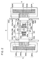
- Fig. 2 illustrates the optical head 2 and the linear motor 5 as the top plan view thereof.
- Fig. 3 shows cross sections of the optical head 2, the magnetic head 3, the disk 1 and the linear motor 5 (along the radial direction of disk).
- the optical head 2 has an unrepresented laser source, which emits a light beam.
- the objective lens 103 focuses the light beam to form a fine spot on a recording layer la in the disk 1.
- Focusing coils 105 and tracking coils 104 are mounted on a lens holder 107 for holding the objective lens 103 in a supported state by plate springs 108.
- a magnetic force acts between the coils and actuator magnets 109 or actuator yokes 106 fixed on a base 100.
- the magnetic force moves the objective lens to scan the beam thereby so that the fine spot may accurately trace a recording track formed on the recording layer la in disk 1, performing so-called tracking operation and focusing operation.
- the thus arranged actuator is mounted on a carriage 101.
- the linear motor 5 is constructed of linear motor yokes 200 to each of which a linear motor magnet 201 is attached, guides 203, and linear motor coils 202 attached to the carriage 101 for the actuator.
- a current is supplied to the linear motor coils 202, a magnetic force acts between the coils and the linear motor magnets 201 or the linear motor yokes 200.
- the magnetic force moves the carriage 101 in the radial direction of disk 1 to perform the seek operation.
- the carriage 101 is arranged to move on the guide rails 203 through rollers 102.
- the magnetic head 3 is composed of a U-shaped core 3a made of a magnetic material, a coil 3b wound around a main pole of the core 3a, and a slider 3c made of a hard material such as ceramics.
- the main pole and opposed pole of core 3a are arranged to face the disk.
- a current modulated according to the information signal is supplied to the coil 3b in magnetic head 3, whereby a bias field modulated according to the information signal is applied from the main pole to the recording layer la in disk 1 in the direction normal thereto.
- the optical head 2 focuses the light beam to form a fine spot irradiating a region to which the bias field is applied on the recording layer 1a.
- the temperature increases in the portion irradiated by the light beam in the recording layer la to suddenly decrease the coercive force therein.
- magnetization is recorded corresponding to the direction of applied bias field.
- the thus magnetized portion leaves the irradiated portion by the light beam, whereby the temperature again decreases. With the temperature decrease, the coercive force suddenly increases to maintain the recorded magnetization. In this manner, information is recorded in a pattern of magnetization corresponding to the information signal.
- electromagnetic drive means is used in general as the actuator or the linear motor for optical head in magneto-optical recording apparatus.
- magnetism could leak from magnets in the drive means, and the leaking magnetism sometimes acts near the magnetic head in recording the information signal. It was pointed out heretofore as a problem that such leaking field had components in the direction perpendicular to the disk which was added as offset to the modulated field generated by the magnetic head and that poor signal recording could result if the recording of information signal was carried out in the state that the field with offset was applied to the disk.
- a solution to this problem was already proposed (as in Japanese Laid-open Patent Application No. 3-259444).
- the poor signal recording is caused not only by the perpendicular components of the leaking field acting near the magnetic head to the disk but also by the magnetization induced inside the core by horizontal components.
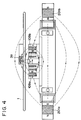
- FIG. 4 shows a case in which a pair of actuator magnets 109 and a pair of linear motor magnets 201 are arranged with opposed faces being opposite magnetic poles (i.e., such that N-pole of right magnet 109b or 201b is opposed to S-pole of left magnet 109a or 201a), in which broken lines represent schematic lines of magnetic force of leaking fields from the magnets.
- Fig. 5 is an enlarged drawing to show the state of the leaking fields near the core 3a in the magnetic head shown in Fig. 4.
- the direction of leaking fields as shown by broken lines is parallel to the disk 1 in the vicinity of the core 3a but there are little perpendicular components to the disk 1.
- magnetization is induced inside the core 3a while distributed on the sides of main pole 3mp and opposed pole 3sp as shown by signs + and - in Fig. 5.
- a magnetic field caused by this magnetization has lines of magnetic force as shown by solid lines in Fig. 5, which leave the ends of main pole 3mp of core 3a and reach the ends of the opposed pole 3sp.
- This magnetic field acts in the perpendicular direction to the portion irradiated by the light beam in the recording layer la in disk 1 immediately below the main pole 3mp. Consequently, even if the leaking fields from the actuator magnets and from the linear motor magnets have only the parallel components but no perpendicular components to the disk, the magnetic field caused by the magnetization of core acts also in the perpendicular direction to the disk, which is added as offset in recording the information signal and therefore could be a cause of the poor signal recording.
- the shape of core is asymmetric with respect to the main pole.
- the shape of core is not symmetric with respect to the main pole in most cases because of issues in production.
- the core is usually formed approximately in a U shape, as shown, including a ring head. Therefore, such problem is very serious.
- the above problem is rarely caused by a radial component on the disk (which is a component perpendicular to the plane of Fig. 4 or Fig. 5) among the parallel components to the disk in the leaking field.
- the above problem is mainly caused by a tangential component to the disk (which is a parallel component to the plane of Fig. 4 or Fig. 5).
- a magneto-optical recording apparatus comprises an actuator for electromagnetically driving an objective lens for focusing a light beam to form a fine spot on a magneto-optical disk so as to effect focusing and tracking, a magnetic head for applying a magnetic field to a portion irradiated by the light beam on the magneto-optical disk, and a linear motor for electromagnetically driving the objective lens and the magnetic head in a united or synchronized manner to effect the seek operation in the radial direction of magneto-optical disk, in which the magnetic head is provided with a substantially U-shaped core having a main pole facing the magneto-optical disk and an opposed pole opposed to the main pole and in which a direction of a leaking field produced by the actuator and the linear motor is substantially parallel near the magnetic head to a diagonal line connecting between a corner of the opposed pole of the core and a corner located diagonal thereto.
- This arrangement can surely prevent the poor information recording due to the influence of leaking field.
- the actuator magnets and the linear motor magnets are arranged such that leaking fields appearing from the actuator and from the linear motor have parallel components to the magneto-optical disk, which cancel each other at least in the vicinity of the magnetic head, whereby the poor information recording due to the influence of leaking field can be surely prevented.
- Fig. 6 shows an example in which a pair of actuator magnets 109 are arranged to have mutually opposed faces as same magnetic poles (N-poles opposed to each other in the present embodiment) and a pair of linear motor magnets 201 are arranged to have mutually opposed faces as different magnetic poles (N-pole of right magnet 201b and S-pole of left magnet 201a opposed to each other in the present embodiment), in which broken lines show approximate lines of magnetic force of leaking fields.
- a leaking field from the actuator magnets 109 is perpendicular to the disk 1 near the core 3a in a magnetic head (as directed upward) and a leaking field from the linear motor magnets 201 is parallel to the disk 1 near the core 3a in the magnetic head (as directed from right to left). Consequently, a composite field of the leaking fields from the actuator magnets 109 and from the linear motor magnets 201 is oblique from right bottom to left top, as shown in Fig. 7 (which shows an enlarged state near the core 3a).
- the direction of the composite field is approximately parallel to a diagonal line A connecting between a bottom corner of opposed pole 3sp of core 3a and a top corner located diagonal thereto in the core 3a.
- magnetization is induced inside the core 3a as distributed as shown by signs - and + in Fig. 7 near the corner of opposed pole 3sp and near the corner located diagonal thereto.
- This magnetization produces a magnetic field with lines of magnetic force as shown by the solid lines in Fig. 7, which are concentrated near the corner of opposed pole 3sp and near the corner located diagonal thereto where the above magnetization is distributed.
- the magnetization produces no magnetic field at the free end of main pole 3mp where the magnetization distribution is rare.
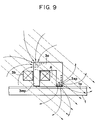
- FIG. 8 shows an example in which a pair of actuator magnets 109 are arranged to have mutually opposed faces as different magnetic poles (S-pole of right magnet 109b and N-pole of left magnet 109a opposed to each other in the present embodiment) and a pair of linear motor magnets are arranged to have mutually opposed faces as same magnetic poles (S-poles opposed to each other in the present embodiment), in which broken lines represent approximate lines of magnetic force of leaking fields.
- a leaking field from actuator magnets 109 is parallel to the disk 1 near the core 3a in magnetic head (as directed from left to right) and a leaking field from linear motor magnets 201 is perpendicular to the disk 1 near the core 3a in magnetic head (as directed downward). Consequently, a composite field of the leaking fields from the actuator magnets 109 and from the linear motor magnets 201 is oblique from left top to right bottom as shown in Fig. 9 (which shows an enlarged state near the core). Also in this example, similarly as in the previous embodiment, the direction of the composite field is approximately parallel to a diagonal line A connecting between the bottom corner of opposed pole 3sp of core 3a and the top corner located diagonal thereto.
- magnetization is induced inside the core 3a as distributed as shown by signs + and - in Fig. 9 near the bottom corner of opposed pole 3sp and near the top corner located diagonal thereto.
- This magnetization produces a magnetic field having lines of magnetic force as shown by the solid lines in Fig. 9, which are concentrated near the corner of opposed pole 3sp and near the corner located diagonal thereto where the above magnetization is distributed.
- the important point is that the direction of composite field of leaking fields from the actuator magnets and from the linear motor magnets is substantially parallel to the diagonal line connecting between the corner of opposed pole 3sp and the corner located diagonal thereto in the vicinity of the core in magnetic head, but it is inessential whether the direction of magnetic field is directed from left top to right bottom or from right bottom to left top.
- the embodiment shown in Fig. 6 may be modified such that the S-poles in the actuator magnet 109 are arranged to be opposed each other, and the S-pole of the right magnet 201b in the linear motor magnet 201 is opposed to the N-pole of the left magnet 201a in the linear motor magnet 201.
- the embodiment shown in Fig. 8 may be modified such that the N-poles in the linear motor magnet 201 are mutually opposed and the N-pole of the right magnet 109b in the actuator magnet 109 is opposed to the S-pole of the left magnet 109a in the actuator magnet 109.
- the optimum direction of composite field is not always parallel to the diagonal line connecting between the corner of opposed pole and the corner located diagonal thereto.
- the optimum direction of field is related to the shape of core and should be considered to drop within the range of about ⁇ 30° with respect to the diagonal line. For example, in case a ratio of height to width of core is 1:1, the optimum direction of composite field of leaking fields is about 20° closer to the disk than the diagonal line, approaching the parallel direction to the disk (whereby the incident angle of magnetic field is about 25° to the disk).
- actuator and linear motor as described was shown as an example and that the arrangement of the present invention can be applicable to any of various conventional constructions of actuator and linear motor. Specifically, the invention can be applied to an example employing an actuator and a linear motor each having at least a pair of permanent magnets located on the both sides of magnetic head. This example has a great degree of freedom in designing.
- the example permits the permanent magnets to be properly arranged in position, whereby such an arrangement can be easily achieved that one pair of permanent magnets produce a leaking field approximately parallel to the disk near the magnetic head while another pair of permanent magnets produce a leaking field approximately perpendicular to the disk near the magnetic head and that a composite field of the leaking fields produced by the two pairs of permanent magnets is approximately parallel to a diagonal line connecting a corner of opposed pole of core and a corner located diagonal thereto near the magnetic head.
- FIG. 10 shows an example in which a pair of actuator magnets 109 are arranged to have mutually opposed faces as different magnetic poles (S-pole of right magnet 109b and N-pole of left magnet 109a opposed to each other in the present embodiment) and a pair of linear motor magnets 201 also have mutually opposed faces as different magnetic poles which are reversed in pole location from that of the above actuator magnets 109 (i.e., N-pole of right magnet 201b and S-pole of left magnet 201a opposed to each other), in which broken lines represent approximate lines of magnetic force of leaking fields.
- a leaking field from the actuator magnets 109 is parallel to the disk 1 near the core 3a in magnetic head (as directed from left to right) and a leaking field from the linear motor magnets 201 is also parallel to the disk 1 near the core 3a in magnetic head but opposite in direction to the direction of leaking field from the actuator magnets 109 (thus the field from the linear motor magnets 201 is directed from right to left). Further, the leaking field from the actuator magnets 109 is arranged to have a strength approximately equal to that of the leaking field from the linear motor magnets 201 near the core 3a in magnetic head.
- the present embodiment is so arrangement that both the leaking fields from the actuator magnets and from the linear motor magnets are parallel to the disk near the core in magnetic head and have no perpendicular components
- another arrangement different from the arrangement in the present embodiment can be employed.
- leaking fields from the actuator magnets and from the linear motor magnets may have both parallel components and perpendicular components to the disk near the core in magnetic head.
- the parallel components of leaking fields to the disk should be arranged to cancel each other as in the above embodiment and influence of the perpendicular components can be avoided by also using well-known means (for example by providing a magnet near the magnetic head to cancel the magnetic field).
- the present invention is more effective in particular for apparatus having a leaking field with tangential components to the disk among parallel components to the disk.
- a magneto-optical recording apparatus comprises an actuator for electromagnetically driving an objective lens for focusing a light beam to form a fine spot on a magneto-optical disk so as to effect focusing and tracking, a magnetic head for applying a magnetic field to a portion irradiated by the light beam on the magneto-optical disk, and a linear motor for electromagnetically driving the objective lens and the magnetic head in a united or synchronized manner to effect the seek operation in the radial direction of magneto-optical disk, in which the magnetic head is provided with a substantially U-shaped core having a main pole facing the magneto-optical disk and an opposed pole opposed to the main pole and in which a direction of a leaking field produced by the actuator and the linear motor is substantially parallel near the magnetic head to a diagonal line connecting between a corner of the opposed pole of the core and a corner located diagonal thereto.
- the actuator magnets and the linear motor magnets are arranged such that the leaking fields from the actuator and from the linear motor are formed to cancel at least parallel components to the magneto-optical disk near the magnetic head.
- the leaking fields do not induce magnetization at the distal end of main pole of core, so that there is no magnetic field acting as offset in the irradiated portion by the light beam on disk in recording the information signal, thus enabling excellent information recording.
- a requirement is that a composite field of the leaking field from the actuator magnets and the leaking field from the linear motor magnets is oblique in the vicinity of core 3a.
- the present invention is of course applicable to apparatus employing a ring head with a gap provided in a part of magnetic path.
Landscapes
- Recording Or Reproducing By Magnetic Means (AREA)
Applications Claiming Priority (3)
| Application Number | Priority Date | Filing Date | Title |
|---|---|---|---|
| JP355331/92 | 1992-12-21 | ||
| JP4355331A JP2980273B2 (ja) | 1992-12-21 | 1992-12-21 | 光磁気記録装置 |
| JP35533192 | 1992-12-21 |
Publications (3)
| Publication Number | Publication Date |
|---|---|
| EP0604159A2 true EP0604159A2 (fr) | 1994-06-29 |
| EP0604159A3 EP0604159A3 (fr) | 1994-12-14 |
| EP0604159B1 EP0604159B1 (fr) | 1999-08-25 |
Family
ID=18443315
Family Applications (1)
| Application Number | Title | Priority Date | Filing Date |
|---|---|---|---|
| EP93310297A Expired - Lifetime EP0604159B1 (fr) | 1992-12-21 | 1993-12-20 | Dispositif d'enregistrement magnéto-optique |
Country Status (4)
| Country | Link |
|---|---|
| US (1) | US5563853A (fr) |
| EP (1) | EP0604159B1 (fr) |
| JP (1) | JP2980273B2 (fr) |
| DE (1) | DE69326128T2 (fr) |
Families Citing this family (9)
| Publication number | Priority date | Publication date | Assignee | Title |
|---|---|---|---|---|
| US5745470A (en) * | 1995-05-31 | 1998-04-28 | Kabushiki Kaisha Toshiba | Head moving apparatus which cancels leakage flux |
| JP3070516B2 (ja) * | 1997-04-28 | 2000-07-31 | 日本電気株式会社 | 光ディスク装置 |
| JP2000030203A (ja) | 1998-05-07 | 2000-01-28 | Canon Inc | 磁気ヘッド用コイル、光磁気記録用磁気ヘッドおよび光磁気記録装置 |
| JP3507360B2 (ja) | 1998-05-07 | 2004-03-15 | キヤノン株式会社 | 磁気ヘッド用平面コイル部品、光磁気記録用磁気ヘッドおよび光磁気記録装置 |
| DE19822256C2 (de) * | 1998-05-18 | 2002-07-11 | Zeiss Carl Jena Gmbh | Anordnung zur direkten Steuerung der Bewegung eines Zoomsystems in einem Stereomikroskop |
| JP2000048422A (ja) | 1998-07-30 | 2000-02-18 | Canon Inc | 光磁気記録用磁気ヘッドおよび光磁気記録装置 |
| JP2001067748A (ja) | 1999-08-31 | 2001-03-16 | Canon Inc | 光磁気記録ヘッドおよび光磁気記録装置 |
| JP2001229589A (ja) | 2000-02-16 | 2001-08-24 | Canon Inc | 光磁気記録媒体及び光磁気記録装置 |
| JP2004227712A (ja) * | 2003-01-24 | 2004-08-12 | Canon Inc | 磁気ヘッド支持機構 |
Family Cites Families (12)
| Publication number | Priority date | Publication date | Assignee | Title |
|---|---|---|---|---|
| US4658390A (en) * | 1983-04-18 | 1987-04-14 | Sharp Kabushiki Kaisha | Optical focus position control in an optical memory system |
| JP2637415B2 (ja) * | 1987-03-03 | 1997-08-06 | オリンパス光学工業株式会社 | 光磁気記録再生装置 |
| JPH02126403A (ja) * | 1988-11-07 | 1990-05-15 | Mitsubishi Electric Corp | 光磁気記録再生装置 |
| US5126983A (en) * | 1989-04-12 | 1992-06-30 | Olympus Optical Co., Ltd. | Apparatus for optically recording information on opto-magnetic record medium having a minimized leakage magnetic field |
| JPH0312003A (ja) * | 1989-06-09 | 1991-01-21 | Nec Corp | 光磁気ディスク装置 |
| JPH0319161A (ja) * | 1989-06-16 | 1991-01-28 | Ricoh Co Ltd | 光磁気記録装置 |
| JPH03113758A (ja) * | 1989-09-22 | 1991-05-15 | Pioneer Electron Corp | 光磁気ディスクプレーヤ |
| JPH07118106B2 (ja) * | 1990-03-08 | 1995-12-18 | パイオニア株式会社 | 光磁気記録再生装置 |
| JP2877889B2 (ja) * | 1990-04-13 | 1999-04-05 | パイオニア株式会社 | 光磁気記録再生装置 |
| JPH0467364A (ja) * | 1990-07-03 | 1992-03-03 | Canon Inc | 磁気ヘッドアクチュエータ |
| JPH04222903A (ja) * | 1990-12-25 | 1992-08-12 | Olympus Optical Co Ltd | 光磁気ドライブ装置 |
| JPH04310653A (ja) * | 1991-04-08 | 1992-11-02 | Ricoh Co Ltd | 光ディスクドライブ装置 |
-
1992
- 1992-12-21 JP JP4355331A patent/JP2980273B2/ja not_active Expired - Fee Related
-
1993
- 1993-12-20 EP EP93310297A patent/EP0604159B1/fr not_active Expired - Lifetime
- 1993-12-20 DE DE69326128T patent/DE69326128T2/de not_active Expired - Fee Related
-
1995
- 1995-11-02 US US08/556,833 patent/US5563853A/en not_active Expired - Fee Related
Also Published As
| Publication number | Publication date |
|---|---|
| EP0604159A3 (fr) | 1994-12-14 |
| DE69326128T2 (de) | 2000-03-30 |
| US5563853A (en) | 1996-10-08 |
| DE69326128D1 (de) | 1999-09-30 |
| JP2980273B2 (ja) | 1999-11-22 |
| JPH06195606A (ja) | 1994-07-15 |
| EP0604159B1 (fr) | 1999-08-25 |
Similar Documents
| Publication | Publication Date | Title |
|---|---|---|
| US4613962A (en) | Tracking device with linear motor | |
| KR0185972B1 (ko) | 광 픽업 헤드 장치 | |
| US5165088A (en) | Optical pickup with bilateral and vertical symmetry | |
| US5563853A (en) | Magneto-optical recording apparatus that compensates for magnetic fields leaking from an objective lens actuator and a linear motor | |
| JP2637415B2 (ja) | 光磁気記録再生装置 | |
| US4823219A (en) | Carriage recording head sandwiched by electromagnetic coil sections | |
| KR100775944B1 (ko) | 변위 가능형 시준렌즈용 액추에이터를 구비한 광학 주사장치 및 광학 재생장치 | |
| US5226030A (en) | Magneto-optical recording and reproducing device | |
| US5220544A (en) | Magnetic optical disk player having improved magnetic field orientations | |
| EP0355963B1 (fr) | Dispositif de commande des composants optiques pour tête de lecture optique | |
| JPH0232692B2 (fr) | ||
| US5333124A (en) | Magnetic optical disk player having improved servoresponse sensitivity | |
| JP2706265B2 (ja) | 光学ヘッド装置 | |
| JPS6260148A (ja) | 光磁気情報記録再生装置 | |
| KR100819938B1 (ko) | 광학 주사장치 및 그 주사장치를 구비한 광학 재생장치 | |
| JP2560977Y2 (ja) | 光磁気ディスク用ヘッド装置 | |
| JPS61287048A (ja) | 光学系駆動装置 | |
| JPH04222903A (ja) | 光磁気ドライブ装置 | |
| JPH04310653A (ja) | 光ディスクドライブ装置 | |
| JP3105628B2 (ja) | 光学式ピックアップのアクチュエータ | |
| JPS63144430A (ja) | 光学系駆動装置 | |
| JPH0419847A (ja) | 光磁気ディスク装置用リニアモーター | |
| JPH0419846A (ja) | 対物レンズ駆動装置 | |
| JPH07161090A (ja) | 外部磁界発生装置 | |
| JPH04345942A (ja) | 光磁気記録再生装置 |
Legal Events
| Date | Code | Title | Description |
|---|---|---|---|
| PUAI | Public reference made under article 153(3) epc to a published international application that has entered the european phase |
Free format text: ORIGINAL CODE: 0009012 |
|
| AK | Designated contracting states |
Kind code of ref document: A2 Designated state(s): DE FR GB IT NL |
|
| PUAL | Search report despatched |
Free format text: ORIGINAL CODE: 0009013 |
|
| AK | Designated contracting states |
Kind code of ref document: A3 Designated state(s): DE FR GB IT NL |
|
| 17P | Request for examination filed |
Effective date: 19950428 |
|
| 17Q | First examination report despatched |
Effective date: 19970421 |
|
| GRAG | Despatch of communication of intention to grant |
Free format text: ORIGINAL CODE: EPIDOS AGRA |
|
| GRAG | Despatch of communication of intention to grant |
Free format text: ORIGINAL CODE: EPIDOS AGRA |
|
| GRAG | Despatch of communication of intention to grant |
Free format text: ORIGINAL CODE: EPIDOS AGRA |
|
| GRAH | Despatch of communication of intention to grant a patent |
Free format text: ORIGINAL CODE: EPIDOS IGRA |
|
| GRAH | Despatch of communication of intention to grant a patent |
Free format text: ORIGINAL CODE: EPIDOS IGRA |
|
| GRAA | (expected) grant |
Free format text: ORIGINAL CODE: 0009210 |
|
| AK | Designated contracting states |
Kind code of ref document: B1 Designated state(s): DE FR GB IT NL |
|
| PG25 | Lapsed in a contracting state [announced via postgrant information from national office to epo] |
Ref country code: NL Free format text: LAPSE BECAUSE OF FAILURE TO SUBMIT A TRANSLATION OF THE DESCRIPTION OR TO PAY THE FEE WITHIN THE PRESCRIBED TIME-LIMIT Effective date: 19990825 Ref country code: IT Free format text: LAPSE BECAUSE OF FAILURE TO SUBMIT A TRANSLATION OF THE DESCRIPTION OR TO PAY THE FEE WITHIN THE PRE;WARNING: LAPSES OF ITALIAN PATENTS WITH EFFECTIVE DATE BEFORE 2007 MAY HAVE OCCURRED AT ANY TIME BEFORE 2007. THE CORRECT EFFECTIVE DATE MAY BE DIFFERENT FROM THE ONE RECORDED.SCRIBED TIME-LIMIT Effective date: 19990825 |
|
| REF | Corresponds to: |
Ref document number: 69326128 Country of ref document: DE Date of ref document: 19990930 |
|
| ET | Fr: translation filed | ||
| NLV1 | Nl: lapsed or annulled due to failure to fulfill the requirements of art. 29p and 29m of the patents act | ||
| PLBE | No opposition filed within time limit |
Free format text: ORIGINAL CODE: 0009261 |
|
| STAA | Information on the status of an ep patent application or granted ep patent |
Free format text: STATUS: NO OPPOSITION FILED WITHIN TIME LIMIT |
|
| 26N | No opposition filed | ||
| REG | Reference to a national code |
Ref country code: GB Ref legal event code: IF02 |
|
| PGFP | Annual fee paid to national office [announced via postgrant information from national office to epo] |
Ref country code: GB Payment date: 20031208 Year of fee payment: 11 |
|
| PGFP | Annual fee paid to national office [announced via postgrant information from national office to epo] |
Ref country code: FR Payment date: 20031222 Year of fee payment: 11 |
|
| PGFP | Annual fee paid to national office [announced via postgrant information from national office to epo] |
Ref country code: DE Payment date: 20031223 Year of fee payment: 11 |
|
| PG25 | Lapsed in a contracting state [announced via postgrant information from national office to epo] |
Ref country code: GB Free format text: LAPSE BECAUSE OF NON-PAYMENT OF DUE FEES Effective date: 20041220 |
|
| PG25 | Lapsed in a contracting state [announced via postgrant information from national office to epo] |
Ref country code: DE Free format text: LAPSE BECAUSE OF NON-PAYMENT OF DUE FEES Effective date: 20050701 |
|
| GBPC | Gb: european patent ceased through non-payment of renewal fee |
Effective date: 20041220 |
|
| PG25 | Lapsed in a contracting state [announced via postgrant information from national office to epo] |
Ref country code: FR Free format text: LAPSE BECAUSE OF NON-PAYMENT OF DUE FEES Effective date: 20050831 |
|
| REG | Reference to a national code |
Ref country code: FR Ref legal event code: ST |