EP0604316A1 - Vorrichtung zur Verriegelung der Typenräder einer Frankiermaschine - Google Patents
Vorrichtung zur Verriegelung der Typenräder einer Frankiermaschine Download PDFInfo
- Publication number
- EP0604316A1 EP0604316A1 EP93403144A EP93403144A EP0604316A1 EP 0604316 A1 EP0604316 A1 EP 0604316A1 EP 93403144 A EP93403144 A EP 93403144A EP 93403144 A EP93403144 A EP 93403144A EP 0604316 A1 EP0604316 A1 EP 0604316A1
- Authority
- EP
- European Patent Office
- Prior art keywords
- drum
- stirrup
- unlocking
- tilting
- knobs
- Prior art date
- Legal status (The legal status is an assumption and is not a legal conclusion. Google has not performed a legal analysis and makes no representation as to the accuracy of the status listed.)
- Granted
Links
Images
Classifications
-
- G—PHYSICS
- G07—CHECKING-DEVICES
- G07B—TICKET-ISSUING APPARATUS; FARE-REGISTERING APPARATUS; FRANKING APPARATUS
- G07B17/00—Franking apparatus
- G07B17/00459—Details relating to mailpieces in a franking system
- G07B17/00508—Printing or attaching on mailpieces
-
- G—PHYSICS
- G07—CHECKING-DEVICES
- G07B—TICKET-ISSUING APPARATUS; FARE-REGISTERING APPARATUS; FRANKING APPARATUS
- G07B17/00—Franking apparatus
- G07B17/00459—Details relating to mailpieces in a franking system
- G07B17/00508—Printing or attaching on mailpieces
- G07B2017/00516—Details of printing apparatus
- G07B2017/00524—Printheads
- G07B2017/00548—Mechanical printhead
Definitions
- the present invention relates to franking machines, the print head of which is with a printing drum carrying printing rollers. It relates more particularly in such machines, to a device for locking in position the print wheels.
- These printing wheels are, in known manner, rotatably mounted on the drum to allow them to be adjusted in position, in the absence of a franking operation. They are also slightly protruding on the periphery of the drum and rotatable with it, for printing fixed and variable postage information at each rotation of the drum.
- the dials are used to print variable value and postage date information.
- the printing drum therefore carries two sets of wheels for this variable information, which protrude from the drum through suitable openings in a plate engraved with postal stickers.
- This engraved plate marries the periphery of the drum and carries the fixed postage information, in the form of imprints of the postage sticker and of the home office sticker, or another defined form.
- This same drum generally carries, in addition, another engraved plate called advertising similar to the first but often retractable mounted, which is assigned to the printing of fixed advertising information.
- other printing means such as one or more retractable pads are associated with the drum.
- knobs are generally coupled to a motorized or manual control assembly with so-called driving pinions driving, by a kinematic connection, so-called pinions driven on the wheels.
- the motorized control unit is then connected to a control card itself connected to a data input means, for example a keyboard with display screen on the machine.
- the object of the present invention is, once this adjustment has been made, to lock the racks and the printing knobs during their rotation with the drum at each printing cycle.
- said unlocking finger is a centering finger of another member of the franking machine which is intended to cooperate with a guide opening which is made accordingly in the body of the printing drum.
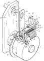
- the rotary printing drum 1 which normally equips the head of a franking machine.
- the drum 1 is assumed to carry six coaxial printing wheels 2. When these wheels are not locked, it is possible to modify their setting, that is to say to modify the number or the letter which they print, by turning these knobs on themselves around their common axis 3.
- each wheel 2 is secured to a coaxial toothed wheel 4 which can, when it is unlocked as will be seen below. after, be driven in rotation by a kinematic link itself controlled from the keyboard of the franking machine.
- knobs 2 are locked in position during the rotation of the printing drum, so that their setting cannot be modified, accidentally or not, during the printing operation of the values carried by these knobs. It is of course also necessary that they can be unlocked when the drum is in the rest position, and they can only be unlocked in this rest position.
- the locking must be positive and therefore without risks. This would not be the case, for example, if it depended solely on a return spring that could accidentally break while the print drum was being rotated.
- the device of the invention which will now be described and which equips the drum 1, makes it possible to satisfy these requirements.
- This locking device basically comprises a locking stirrup 5 which is pivotally mounted around an axis 6 fixed on the drum 1 and parallel to the axis 3 of the knurls 2.
- This tilting stirrup 5 has as many locking teeth 7 as there are knurls 2, ie five teeth 7 in the simplified example which is shown here. These teeth 7 are shaped and arranged to respectively engage in a tooth of the toothed wheel 4 associated with each wheel 2, thereby locking each of these wheels in position, when the stirrup 5 is tilted forward under the action of a powerful return spring 8 which is stretched between a stud 9 secured to the drum 1 and another stud 10 which is secured to an arm 11 of the stirrup 5, this stud 10 being placed on this arm 11, under the axis 6 so that the action of the spring 8 tends to cause the stirrup 5 to tilt forwards and therefore to engage the locking teeth 7 in the toothed wheels 4.
- a powerful return spring 8 which is stretched between a stud 9 secured to the drum 1 and another stud 10 which is secured to an arm 11 of the stirrup 5, this stud 10 being placed on this arm 11, under the axis 6 so that the action of the spring 8 tends to cause the stirrup 5 to
- a first free end 14 of this lever 12 comes to bear against a stop 15 integral with the stirrup 5.
- the other free end 16 of the lever 12 has a lateral bulge 17 intended to cooperate with an external control finger 18 with a conical end 19. This finger passes through a guide orifice 20 formed in the body of the printing drum 1.
- This arm 11 has, as shown, its free end 24 permanently engaged in a notch 25 of a locking safety pull tab 26 which is slidably mounted, by means of a slide 27 secured to the drum 1, on one of the generators of said drum 1 .
- the tilting, shown in dotted lines, of the arm 11 can only be done by sliding, as indicated by the arrows, the pull tab 26 along said generatrix of the drum which is coaxial with it.
- the free end 29 of the pull tab 26 which is opposite to that 28 which is adjacent to the notch 25 and which forms the retaining stop for this pull tab, is extended by a jumper 30 in "inverted U" shape.
- This jumper 30 is designed to ride without friction a conjugated flange 31 which is part of the frame 22 for supporting the drum 1 and which is coaxial with this. latest .
- An opening or notch 32 is provided in this flange 31 and is positioned there such that the jumper 30 comes to overlap this opening when the drum 1 is in its rest position. None then prevents the sliding of the safety zipper 26 in its slide 27, so that the knobs can be unlocked to adjust them in position.
- the jumper 30 positively overlaps the fixed flange 31.
- the arm 11 is then completely locked in its position which corresponds to the locking of the rollers 2 by the stirrup 5 because the puller 26 can in no case slide along its longitudinal axis.
- the locking of the knobs 2 is then positive because it is ensured even in the event of failure of the return spring 8.
- the unlocking control finger 18 may be a finger only provided for this purpose, but preferably it is positively incorporated in the franking machine in which it simultaneously plays the role of guide finger: this is for example the case when this machine has a removable head containing the printing drum which is designed to mate with a fixed base which in particular includes the control keyboard.
- the finger 18 then also serves, in cooperation with the guide opening 20 of the tab 1A, as a relative centering finger of the head and the base.
- it serves as a guide finger for a set of driving pinions, with associated motors, which are positioned in a tilting module included in the base, this module being tilted towards the head only for the adjustment operations of the knobs and then being guided by cooperation between the finger 18 and the guide opening 20 of the tab 1A of the drum.
Landscapes
- Engineering & Computer Science (AREA)
- Computer Security & Cryptography (AREA)
- Physics & Mathematics (AREA)
- General Physics & Mathematics (AREA)
- Devices For Checking Fares Or Tickets At Control Points (AREA)
Applications Claiming Priority (2)
| Application Number | Priority Date | Filing Date | Title |
|---|---|---|---|
| FR9215497A FR2699711B1 (fr) | 1992-12-22 | 1992-12-22 | Dispositif de verrouillage de molettes d'une machine à affranchir. |
| FR9215497 | 1992-12-22 |
Publications (2)
| Publication Number | Publication Date |
|---|---|
| EP0604316A1 true EP0604316A1 (de) | 1994-06-29 |
| EP0604316B1 EP0604316B1 (de) | 1996-11-27 |
Family
ID=9436932
Family Applications (1)
| Application Number | Title | Priority Date | Filing Date |
|---|---|---|---|
| EP93403144A Expired - Lifetime EP0604316B1 (de) | 1992-12-22 | 1993-12-22 | Vorrichtung zur Verriegelung der Typenräder einer Frankiermaschine |
Country Status (4)
| Country | Link |
|---|---|
| US (1) | US5385090A (de) |
| EP (1) | EP0604316B1 (de) |
| DE (1) | DE69306233T2 (de) |
| FR (1) | FR2699711B1 (de) |
Citations (6)
| Publication number | Priority date | Publication date | Assignee | Title |
|---|---|---|---|---|
| US4160899A (en) * | 1977-12-27 | 1979-07-10 | Pitney-Bowes, Inc. | Detent remover for a postage meter |
| US4345521A (en) * | 1981-01-14 | 1982-08-24 | Pitney Bowes Inc. | Inhibiting means for postage register parcel identification system |
| US4398458A (en) * | 1981-03-23 | 1983-08-16 | Francotyp Gesellschaft Mbh | Adjustment device for postage metering and value stamping machines |
| US4421023A (en) * | 1982-05-20 | 1983-12-20 | Pitney Bowes Inc. | Printer control systems for electronic postage meter |
| US4702164A (en) * | 1984-10-04 | 1987-10-27 | Pitney Bowes Inc. | Value selector security system |
| US4723486A (en) * | 1984-11-05 | 1988-02-09 | Societe D'etude Et De Construction D'appareils De Precision (S.E.C.A.P.) | Device for automatic angular positioning of a plurality of indexable rotary machine elements, and a machine comprising a device of this type, especially a postal franking machine |
Family Cites Families (5)
| Publication number | Priority date | Publication date | Assignee | Title |
|---|---|---|---|---|
| US4127064A (en) * | 1977-03-14 | 1978-11-28 | Hi-Speed Checkweigher Co., Inc. | Large type rotary printer |
| US4220082A (en) * | 1979-05-03 | 1980-09-02 | Esselte Pendaflex Corporation | Print wheel selection mechanism |
| FR2488187A1 (fr) * | 1980-08-08 | 1982-02-12 | Shinshu Seiki Kk | Imprimante de petite taille |
| US4601240A (en) * | 1984-10-04 | 1986-07-22 | Pitney Bowes Inc. | Print drum security system |
| US4936209A (en) * | 1988-12-29 | 1990-06-26 | Pitney Bowes Inc. | Electronic postage meter with zip code location designation |
-
1992
- 1992-12-22 FR FR9215497A patent/FR2699711B1/fr not_active Expired - Fee Related
-
1993
- 1993-12-22 US US08/171,666 patent/US5385090A/en not_active Expired - Fee Related
- 1993-12-22 DE DE69306233T patent/DE69306233T2/de not_active Expired - Fee Related
- 1993-12-22 EP EP93403144A patent/EP0604316B1/de not_active Expired - Lifetime
Patent Citations (6)
| Publication number | Priority date | Publication date | Assignee | Title |
|---|---|---|---|---|
| US4160899A (en) * | 1977-12-27 | 1979-07-10 | Pitney-Bowes, Inc. | Detent remover for a postage meter |
| US4345521A (en) * | 1981-01-14 | 1982-08-24 | Pitney Bowes Inc. | Inhibiting means for postage register parcel identification system |
| US4398458A (en) * | 1981-03-23 | 1983-08-16 | Francotyp Gesellschaft Mbh | Adjustment device for postage metering and value stamping machines |
| US4421023A (en) * | 1982-05-20 | 1983-12-20 | Pitney Bowes Inc. | Printer control systems for electronic postage meter |
| US4702164A (en) * | 1984-10-04 | 1987-10-27 | Pitney Bowes Inc. | Value selector security system |
| US4723486A (en) * | 1984-11-05 | 1988-02-09 | Societe D'etude Et De Construction D'appareils De Precision (S.E.C.A.P.) | Device for automatic angular positioning of a plurality of indexable rotary machine elements, and a machine comprising a device of this type, especially a postal franking machine |
Also Published As
| Publication number | Publication date |
|---|---|
| FR2699711A1 (fr) | 1994-06-24 |
| DE69306233D1 (de) | 1997-01-09 |
| DE69306233T2 (de) | 1997-04-17 |
| FR2699711B1 (fr) | 1995-02-10 |
| US5385090A (en) | 1995-01-31 |
| EP0604316B1 (de) | 1996-11-27 |
Similar Documents
| Publication | Publication Date | Title |
|---|---|---|
| EP2701944B1 (de) | Selbstdrehender kindersitz zur montage auf einem fahrzeugsitz | |
| FR2870795A1 (fr) | Siege de vehicule et vehicule muni d'un tel siege | |
| EP1894770B1 (de) | Kraftfahrzeugsitz für ein Kind, drehbar zwischen einer Gebrauchsposition und mindestens einer Einstiegsposition, mit einem Haken mit doppeltem Verriegelungsmodus | |
| EP0013647A1 (de) | Wahlvorrichtung, insbesondere für die Gangschaltung eines Fahrrads, und seine Verwendung bei einer Gangschaltung | |
| FR2731662A1 (fr) | Siege de vehicule monte coulissant et a dossier rabattable en avant | |
| EP0069687A1 (de) | Steuervorrichtung zum sicheren Vorwählen und Einhalten von Positionen, insbesondere für Gangschaltungen von Fahrrädern und ähnlichen Fahrzeugen | |
| FR2811362A1 (fr) | Systeme de serrure a combinaison | |
| FR2725946A1 (fr) | Cale a rapporter sur un plan porteur presentant des perforations | |
| EP1518744B1 (de) | Rückenlehnegelenkbeschlag mit zeitlich abgestufter Winkelverstellung | |
| FR2482647A1 (fr) | Serrure a combinaison pour bagages, verrouillable meme hors position de combinaison | |
| FR2526072A1 (fr) | Serrure a combinaison | |
| EP0604316B1 (de) | Vorrichtung zur Verriegelung der Typenräder einer Frankiermaschine | |
| FR2496020A1 (fr) | Ferrure d'articulation pour sieges, notamment pour sieges de vehicules automobiles | |
| EP0047699B1 (de) | Kippbarer Sitz mit umklappbarer Rückenlehne für Fahrzeuge | |
| EP0181804A1 (de) | Vorrichtung zur automatischen Winkeleinstellung einer Mehrzahl von rotierenden schaltbaren Maschinenteilen und Maschine, insbesondere Frankiermaschine die eine solche Vorrichtung enthält | |
| CA1285784C (fr) | Installation de consignation de chariots | |
| WO2003029072A1 (fr) | Bicyclette pliable et procede de pliage | |
| EP0020979B1 (de) | Verfahren und Vorrichtung zum Kuppeln und Trennen eines Motors und eines Druckelementes | |
| EP0604317B1 (de) | Vorrichtung zum Einstellen der Typenräder einer Frankiermaschine | |
| FR2665782A1 (fr) | Dispositif de reglage de molettes d'impression dans un machine a affranchir. | |
| EP0263003A1 (de) | Gelenk, welches eine Entkupplung über einen bestimmten Winkelwert erlaubt und eine grosse Verstellung der Rückenlehne gegenüber der Sitzfläche eines Sitzes zulässt | |
| FR2733132A1 (fr) | Dispositif de reglage de l'inclinaison d'un element articule sur un chassis, notamment d'une nacelle de siege pour enfant sur un chassis | |
| EP0883498B1 (de) | Markierstempel mit programmierbar bewegten prägerädern | |
| EP1750980B1 (de) | Verfahren zum anheben eines sitzes eines kraftfahrzeuges und die entsprechende vorrichtung | |
| BE535569A (de) |
Legal Events
| Date | Code | Title | Description |
|---|---|---|---|
| PUAI | Public reference made under article 153(3) epc to a published international application that has entered the european phase |
Free format text: ORIGINAL CODE: 0009012 |
|
| AK | Designated contracting states |
Kind code of ref document: A1 Designated state(s): DE FR GB NL |
|
| 17P | Request for examination filed |
Effective date: 19940914 |
|
| GRAG | Despatch of communication of intention to grant |
Free format text: ORIGINAL CODE: EPIDOS AGRA |
|
| 17Q | First examination report despatched |
Effective date: 19960214 |
|
| GRAH | Despatch of communication of intention to grant a patent |
Free format text: ORIGINAL CODE: EPIDOS IGRA |
|
| GRAH | Despatch of communication of intention to grant a patent |
Free format text: ORIGINAL CODE: EPIDOS IGRA |
|
| GRAA | (expected) grant |
Free format text: ORIGINAL CODE: 0009210 |
|
| AK | Designated contracting states |
Kind code of ref document: B1 Designated state(s): DE FR GB NL |
|
| PG25 | Lapsed in a contracting state [announced via postgrant information from national office to epo] |
Ref country code: NL Free format text: LAPSE BECAUSE OF FAILURE TO SUBMIT A TRANSLATION OF THE DESCRIPTION OR TO PAY THE FEE WITHIN THE PRESCRIBED TIME-LIMIT Effective date: 19961127 |
|
| REF | Corresponds to: |
Ref document number: 69306233 Country of ref document: DE Date of ref document: 19970109 |
|
| GBT | Gb: translation of ep patent filed (gb section 77(6)(a)/1977) |
Effective date: 19970106 |
|
| NLV1 | Nl: lapsed or annulled due to failure to fulfill the requirements of art. 29p and 29m of the patents act | ||
| PLBE | No opposition filed within time limit |
Free format text: ORIGINAL CODE: 0009261 |
|
| 26N | No opposition filed | ||
| PGFP | Annual fee paid to national office [announced via postgrant information from national office to epo] |
Ref country code: FR Payment date: 19991111 Year of fee payment: 7 |
|
| PGFP | Annual fee paid to national office [announced via postgrant information from national office to epo] |
Ref country code: DE Payment date: 19991129 Year of fee payment: 7 |
|
| PGFP | Annual fee paid to national office [announced via postgrant information from national office to epo] |
Ref country code: GB Payment date: 19991214 Year of fee payment: 7 |
|
| PG25 | Lapsed in a contracting state [announced via postgrant information from national office to epo] |
Ref country code: GB Free format text: LAPSE BECAUSE OF NON-PAYMENT OF DUE FEES Effective date: 20001222 |
|
| GBPC | Gb: european patent ceased through non-payment of renewal fee |
Effective date: 20001222 |
|
| PG25 | Lapsed in a contracting state [announced via postgrant information from national office to epo] |
Ref country code: FR Free format text: LAPSE BECAUSE OF NON-PAYMENT OF DUE FEES Effective date: 20010831 |
|
| REG | Reference to a national code |
Ref country code: FR Ref legal event code: ST |
|
| PG25 | Lapsed in a contracting state [announced via postgrant information from national office to epo] |
Ref country code: DE Free format text: LAPSE BECAUSE OF NON-PAYMENT OF DUE FEES Effective date: 20011002 |