EP0604328A1 - Ensemble optique athermalisé passif avec anneau laminé de fibres pour compensation - Google Patents
Ensemble optique athermalisé passif avec anneau laminé de fibres pour compensation Download PDFInfo
- Publication number
- EP0604328A1 EP0604328A1 EP93420490A EP93420490A EP0604328A1 EP 0604328 A1 EP0604328 A1 EP 0604328A1 EP 93420490 A EP93420490 A EP 93420490A EP 93420490 A EP93420490 A EP 93420490A EP 0604328 A1 EP0604328 A1 EP 0604328A1
- Authority
- EP
- European Patent Office
- Prior art keywords
- beam source
- collimating
- support
- compensation
- thermal
- Prior art date
- Legal status (The legal status is an assumption and is not a legal conclusion. Google has not performed a legal analysis and makes no representation as to the accuracy of the status listed.)
- Ceased
Links
- 230000003287 optical effect Effects 0.000 title claims abstract description 30
- 239000000835 fiber Substances 0.000 title claims abstract description 16
- 239000002131 composite material Substances 0.000 claims abstract description 11
- 238000010276 construction Methods 0.000 claims abstract description 7
- 239000000463 material Substances 0.000 claims description 7
- 239000004734 Polyphenylene sulfide Substances 0.000 claims description 4
- 229920000069 polyphenylene sulfide Polymers 0.000 claims description 4
- 229920000049 Carbon (fiber) Polymers 0.000 claims description 3
- 239000004917 carbon fiber Substances 0.000 claims description 3
- 239000011159 matrix material Substances 0.000 claims description 3
- OKTJSMMVPCPJKN-UHFFFAOYSA-N Carbon Chemical compound [C] OKTJSMMVPCPJKN-UHFFFAOYSA-N 0.000 claims description 2
- 229910002804 graphite Inorganic materials 0.000 claims description 2
- 239000010439 graphite Substances 0.000 claims description 2
- 239000004065 semiconductor Substances 0.000 claims description 2
- 238000013461 design Methods 0.000 description 4
- 230000000694 effects Effects 0.000 description 3
- 238000013459 approach Methods 0.000 description 2
- 230000033001 locomotion Effects 0.000 description 2
- 229910000619 316 stainless steel Inorganic materials 0.000 description 1
- XAGFODPZIPBFFR-UHFFFAOYSA-N aluminium Chemical compound [Al] XAGFODPZIPBFFR-UHFFFAOYSA-N 0.000 description 1
- 229910052782 aluminium Inorganic materials 0.000 description 1
- 230000000712 assembly Effects 0.000 description 1
- 238000000429 assembly Methods 0.000 description 1
- 238000005452 bending Methods 0.000 description 1
- 239000004020 conductor Substances 0.000 description 1
- 230000008602 contraction Effects 0.000 description 1
- 239000002657 fibrous material Substances 0.000 description 1
- 239000011261 inert gas Substances 0.000 description 1
- 238000004519 manufacturing process Methods 0.000 description 1
- 238000000034 method Methods 0.000 description 1
- 238000012986 modification Methods 0.000 description 1
- 230000004048 modification Effects 0.000 description 1
- 229920000642 polymer Polymers 0.000 description 1
- 238000009877 rendering Methods 0.000 description 1
- 238000012552 review Methods 0.000 description 1
- 230000035945 sensitivity Effects 0.000 description 1
Images

Classifications
-
- G—PHYSICS
- G02—OPTICS
- G02B—OPTICAL ELEMENTS, SYSTEMS OR APPARATUS
- G02B7/00—Mountings, adjusting means, or light-tight connections, for optical elements
- G02B7/02—Mountings, adjusting means, or light-tight connections, for optical elements for lenses
- G02B7/028—Mountings, adjusting means, or light-tight connections, for optical elements for lenses with means for compensating for changes in temperature or for controlling the temperature; thermal stabilisation
-
- G—PHYSICS
- G02—OPTICS
- G02B—OPTICAL ELEMENTS, SYSTEMS OR APPARATUS
- G02B19/00—Condensers, e.g. light collectors or similar non-imaging optics
- G02B19/0004—Condensers, e.g. light collectors or similar non-imaging optics characterised by the optical means employed
- G02B19/0009—Condensers, e.g. light collectors or similar non-imaging optics characterised by the optical means employed having refractive surfaces only
- G02B19/0014—Condensers, e.g. light collectors or similar non-imaging optics characterised by the optical means employed having refractive surfaces only at least one surface having optical power
-
- G—PHYSICS
- G02—OPTICS
- G02B—OPTICAL ELEMENTS, SYSTEMS OR APPARATUS
- G02B19/00—Condensers, e.g. light collectors or similar non-imaging optics
- G02B19/0033—Condensers, e.g. light collectors or similar non-imaging optics characterised by the use
- G02B19/0047—Condensers, e.g. light collectors or similar non-imaging optics characterised by the use for use with a light source
- G02B19/0052—Condensers, e.g. light collectors or similar non-imaging optics characterised by the use for use with a light source the light source comprising a laser diode
-
- G—PHYSICS
- G02—OPTICS
- G02B—OPTICAL ELEMENTS, SYSTEMS OR APPARATUS
- G02B27/00—Optical systems or apparatus not provided for by any of the groups G02B1/00 - G02B26/00, G02B30/00
- G02B27/09—Beam shaping, e.g. changing the cross-sectional area, not otherwise provided for
-
- G—PHYSICS
- G02—OPTICS
- G02B—OPTICAL ELEMENTS, SYSTEMS OR APPARATUS
- G02B27/00—Optical systems or apparatus not provided for by any of the groups G02B1/00 - G02B26/00, G02B30/00
- G02B27/09—Beam shaping, e.g. changing the cross-sectional area, not otherwise provided for
- G02B27/0938—Using specific optical elements
- G02B27/0994—Fibers, light pipes
-
- H—ELECTRICITY
- H01—ELECTRIC ELEMENTS
- H01S—DEVICES USING THE PROCESS OF LIGHT AMPLIFICATION BY STIMULATED EMISSION OF RADIATION [LASER] TO AMPLIFY OR GENERATE LIGHT; DEVICES USING STIMULATED EMISSION OF ELECTROMAGNETIC RADIATION IN WAVE RANGES OTHER THAN OPTICAL
- H01S5/00—Semiconductor lasers
- H01S5/005—Optical components external to the laser cavity, specially adapted therefor, e.g. for homogenisation or merging of the beams or for manipulating laser pulses, e.g. pulse shaping
-
- H—ELECTRICITY
- H01—ELECTRIC ELEMENTS
- H01S—DEVICES USING THE PROCESS OF LIGHT AMPLIFICATION BY STIMULATED EMISSION OF RADIATION [LASER] TO AMPLIFY OR GENERATE LIGHT; DEVICES USING STIMULATED EMISSION OF ELECTROMAGNETIC RADIATION IN WAVE RANGES OTHER THAN OPTICAL
- H01S5/00—Semiconductor lasers
- H01S5/02—Structural details or components not essential to laser action
- H01S5/022—Mountings; Housings
- H01S5/0225—Out-coupling of light
- H01S5/02253—Out-coupling of light using lenses
-
- H—ELECTRICITY
- H01—ELECTRIC ELEMENTS
- H01S—DEVICES USING THE PROCESS OF LIGHT AMPLIFICATION BY STIMULATED EMISSION OF RADIATION [LASER] TO AMPLIFY OR GENERATE LIGHT; DEVICES USING STIMULATED EMISSION OF ELECTROMAGNETIC RADIATION IN WAVE RANGES OTHER THAN OPTICAL
- H01S5/00—Semiconductor lasers
- H01S5/02—Structural details or components not essential to laser action
- H01S5/024—Arrangements for thermal management
-
- H—ELECTRICITY
- H01—ELECTRIC ELEMENTS
- H01S—DEVICES USING THE PROCESS OF LIGHT AMPLIFICATION BY STIMULATED EMISSION OF RADIATION [LASER] TO AMPLIFY OR GENERATE LIGHT; DEVICES USING STIMULATED EMISSION OF ELECTROMAGNETIC RADIATION IN WAVE RANGES OTHER THAN OPTICAL
- H01S5/00—Semiconductor lasers
- H01S5/02—Structural details or components not essential to laser action
- H01S5/024—Arrangements for thermal management
- H01S5/02407—Active cooling, e.g. the laser temperature is controlled by a thermo-electric cooler or water cooling
- H01S5/02415—Active cooling, e.g. the laser temperature is controlled by a thermo-electric cooler or water cooling by using a thermo-electric cooler [TEC], e.g. Peltier element
Definitions
- the present invention relates to means for effecting temperature-compensation of focal length in an optical assembly.
- Certain optical assemblies such as those found in laser beam output scanners require a stable monochromatic collimated light beam provided by a beam source, such as a laser diode, and a collimating lens.
- a beam source such as a laser diode
- the beam source must maintain a predetermined beam quality over a wide ambient temperature range.
- the relative position between the collimating lens and beam source known as the back focal length, must be maintained over a substantial range of ambient temperature variation.
- the allowable variance of this back focal length depends on the resolution of the scanner.
- the successful implementation of a very high resolution (e.g., 1,000 dpi) laser beam output scanner may, for example, tolerate no more than 20 microinches of back focal length deviation.
- the beam source and lens are mounted in a mechanical structure that attempts to maintain the back focal length while the apparatus undergoes temperature-induced structural changes.
- the athermalization (i.e., thermal compensation) of the beam source is effected either passively or actively.
- Passive compensation systems typically rely on the differences in coefficients of thermal expansions of the various elements in the optical system such that there is minimal net focus shift with temperature.
- the conventional approach is to employ concentric tube systems, which, if constructed from common materials, are too large or bulky.
- U.S. Patent No. 4,730,335 discloses a series of interlocking tubes each carrying a single optical element of an optically-pumped solid-state laser.
- the accuracy of a passive system will depend upon the CTE of the materials chosen for the construction of certain components of the system.
- a preferred embodiment of an apparatus for providing athermalized collimation of a light beam source by a light beam collimating means may be constructed according to the present invention to include beam source support means for fixing the beam source at a predetermined position thereon and for thereby defining a light beam optical axis; collimating means support for aligning the collimating means at a beam collimating means position on the optical axis; and thermal compensation means operatively connected between the beam source support means and the collimating means support.
- the thermal compensation means is operable to selectively displace the collimating means along the optical axis and thereby displace the collimating means.
- the thermal compensation means comprises a composite laminate construction of fiber strands, wherein the coefficient of thermal expansion a of the thermal compensation means is determined by the alignment of the fiber strands.
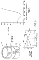
- Figures 1 and 2 are simplified side sectional views of an optical assembly constructed according to the present invention.
- Figure 3 is a simplified diagrammatic model useful in the analysis of the support tube in the optical assembly of Figure 1.
- Figure 4 is a simplified graphical representation of the change in coefficient of thermal expansion (CTE) according to wrap angle in the fibers of the compensation ring in the optical assembly of Figure1.
- CTE coefficient of thermal expansion
- Figure 5 is a graphical representation of the change in focal distance of the assembly of Figure 1 according to ambient temperature.
- a preferred embodiment of the present invention may be constructed as an athermalized optical assembly 20 for use in providing a collimated light beam 22 of essentially constant quality over a wide range of operating temperature.
- a front plate 23 holds a collimating lens 24, located in the lens barrel 26, the combination of which are supported by a compensation ring 27 aligned with the optical axis of a light beam 22 from a beam source 25.
- the beam source 25 is preferably in the form of a semiconductor laser diode fixed in a beam source mount 29 that is integral with a base plate 28. Radial and angular alignment of the lens 24 to the beam source 25 is maintained due to the coaxially aligned, cylindrical geometry of the front plate 23, base plate 28, beam source mount 29, and compensation ring 27.
- the beam source mount 29 and thus the beam source 25 are cooled by a thermal element, preferably in the form of a thermo-electric cooler (TEC) module 40 and heatsink 41 to maintain the beam source at a constant temperature for optimum performance.
- the thermal element is mounted to the back surface of the beam source mount 29.
- the thermal element includes a central passage 42 for the provision of appropriate power and control signal conductors (not shown) to the beam source 25.
- a preferred beam source 25 is a laser diode commercially available as the Hitachi Model HL7806G laser diode.
- the thermal element 40 is preferably a thermoelectric cooler (TEC) module 40 commercially available as the Marlow Industries Model SD1507 (modified to include a center hole for wire routing) that is clamped or cemented between the beam source mount 29 and a black anodized aluminum radial fin heat sink 41.
- the collimating lens 24 is preferably a lens commercially available from Eastman Kodak Company as the Model Q-28 collimating lens.
- the front plate 23 and base plate 28 is preferably constructed of no. 316 stainless steel. Insulating means (not shown) would also be preferred between the base plate and any external frame members to thermally isolate the entire optical assembly 20. With the exception of the particular teachings herein, the assembly 20 is contemplated as being manufactured, aligned, and focussed according to optical techniques known in the art.
- the pertinent design parameters of the preferred embodiment will be understood.
- L, h1, h2 are fixed by the space limitations, and vary with each application.
- the front plate 23 and base plate 28 are separated by a compensation ring 27 having a particular composite laminate construction.
- the laminate thickness is constructed with minimal thickness to reduce bending moments in either plates.
- Multiple layers of laminae fiber orientations are configured to yield a selectable range of positive or negative coefficients of thermal expansion (CTE) that heretofore have been difficult or impossible to achieve in conventional apparatus. Accordingly, the designer of a passively athermalized optical assembly, in following the teachings of the present invention, will find a greater range of CTE values available in the embodiments described herein.
- Figure 3 illustrates a preferred embodiment of the compensation ring 27.
- Figure 4 illustrates the range of a3 (the coefficient of thermal expansion for the compensation ring) that may be selected according to the wrap angle q of the fiber strands 27S in the component fiber layers 27A, 27B, and 27C.
- This composite tube construction allows one to select the desired value of a3 for the compensation ring 27 by varying the wrap angles of the strands in the inner layer 27A and the outer layer 27C while maintaining the strands of the middle layer 27B in a zero wrap angle (i.e., oriented in parallel with the longitudinal axis of the compensation ring).
- the compensation ring is preferably a composite made of plural carbon fibers having a modulus of 33msi, with a Polyphenylene Sulfide matrix, in a precision wrap configuration. Such a matrix may be formed as a layup with unidirectional graphite/polyphenylene sulfide layers.
- the aforementioned composite material is commercially available from Polymer Composites Incorporated. However, it is contemplated that other similar fiber materials, and other fiber/laminate combinations, will yield similar (although potentially less optimal) results.
- a3 (dZ-h1a1-h2a2) / L
- Figure 5 illustrates the effect of the resulting lens motion and focal shift on the effective focal distance over the operating range of the optical assembly 20.
- the system optical focus shift (illustrated as line A) includes the effects of changes in lens focal length and the relative beam source position.
- the expansion or contraction of the compensation ring 27 causes a collimating lens position shift (line B) that exactly compensates the focus shift (line A), whereby the focal distance (line C) of the collimated light beam 22, and hence the beam spot size at the optical assembly focal plane (not shown), will be maintained over the entire operating range T1 - T2 of the optical assembly.
- the collimating lens position shift (line B) is linear; although a positive shift is illustrated, the shift may be either positive or negative according to the selection of the wrap angles discussed hereinabove.
- the contemplated optical assembly may be constructed so as to fully compensate for focus shifts at temperatures below (e.g., T1) and above (e.g., T2) the normal operating value (T0).
- An athermalized optical assembly constructed according to the present invention affords the following, and other, benefits and advantages.
- the components of the assembly may be easily produced and can be successfully designed to minimize component sensitivity to manufacturing tolerances.
- the assembly may be standardized in a compact size that is nonetheless suitable for addressing a wide range of thermal compensation requirements.
- the compact design has less mass, thus allowing faster thermal response.
- the present invention allows optimal thermal compensation by accurate control of a3, the coefficient of thermal expansion of the compensation ring.
- a continuous range of both positive and negative CTE's are available for a3 and therefore the preferred embodiment offers greater thermal compensation accuracy and control.
- the assembly may be constructed so as to be filled with inert gas before final lens alignment, and thus offers both a degree of mechanical protection and a sealed environment for the beam source.
Landscapes
- Physics & Mathematics (AREA)
- General Physics & Mathematics (AREA)
- Optics & Photonics (AREA)
- Optical Couplings Of Light Guides (AREA)
- Optical Head (AREA)
Applications Claiming Priority (2)
| Application Number | Priority Date | Filing Date | Title |
|---|---|---|---|
| US07/996,226 US5270869A (en) | 1992-12-23 | 1992-12-23 | Passively athermalized optical assembly incorporating laminate fiber compensation ring |
| US996226 | 1997-12-22 |
Publications (1)
| Publication Number | Publication Date |
|---|---|
| EP0604328A1 true EP0604328A1 (fr) | 1994-06-29 |
Family
ID=25542644
Family Applications (1)
| Application Number | Title | Priority Date | Filing Date |
|---|---|---|---|
| EP93420490A Ceased EP0604328A1 (fr) | 1992-12-23 | 1993-12-10 | Ensemble optique athermalisé passif avec anneau laminé de fibres pour compensation |
Country Status (3)
| Country | Link |
|---|---|
| US (1) | US5270869A (fr) |
| EP (1) | EP0604328A1 (fr) |
| JP (1) | JPH06215397A (fr) |
Cited By (2)
| Publication number | Priority date | Publication date | Assignee | Title |
|---|---|---|---|---|
| US6594204B1 (en) | 1999-03-31 | 2003-07-15 | Sony Corporation | Lens holder, method for manufacturing lens holder, metal die for producing lens holder and objective lens device |
| EP2302432A1 (fr) | 2009-09-25 | 2011-03-30 | JENOPTIK Optical Systems GmbH | Dispositif de déplacement axial en fonction de la température de composants optiques |
Families Citing this family (17)
| Publication number | Priority date | Publication date | Assignee | Title |
|---|---|---|---|---|
| US5444520A (en) * | 1993-05-17 | 1995-08-22 | Kyocera Corporation | Image devices |
| US5469454A (en) * | 1994-05-02 | 1995-11-21 | University Of Central Florida | Mode locked laser diode in a high power solid state regenerative amplifier and mount mechanism |
| US5655189A (en) * | 1994-05-27 | 1997-08-05 | Kyocera Corporation | Image device having thermally stable light emitting/receiving arrays and opposing lenses |
| US5991102A (en) * | 1994-11-25 | 1999-11-23 | Asahi Kogaku Kogyo Kabushiki Kaisha | Beam protecting device |
| US5848082A (en) * | 1995-08-11 | 1998-12-08 | Sdl, Inc. | Low stress heatsink and optical system |
| US5993934A (en) * | 1997-08-06 | 1999-11-30 | Eastman Kodak Company | Near zero CTE carbon fiber hybrid laminate |
| US6465774B1 (en) | 2000-06-30 | 2002-10-15 | Honeywell International Inc. | Method and system for versatile optical sensor package |
| US6643299B1 (en) * | 2000-07-17 | 2003-11-04 | Calmar Optcom, Inc. | Bi-metal and other passive thermal compensators for fiber-based devices |
| KR20030010148A (ko) * | 2001-07-25 | 2003-02-05 | 주식회사 하이닉스반도체 | 이미지 센서 |
| GB2405993A (en) * | 2003-09-11 | 2005-03-16 | Agilent Technologies Inc | An arrangement for dissipating heat in an electro-optical system |
| JP2007123799A (ja) * | 2005-08-24 | 2007-05-17 | Fujifilm Corp | レーザー光源ユニットを備えた光学装置及び画像記録装置 |
| DE102006046416B4 (de) * | 2005-10-04 | 2009-03-12 | Carl Zeiss Ag | Vorrichtung zur Temperaturkompensation eines optischen Systems |
| DE102008047277A1 (de) * | 2008-09-16 | 2010-04-15 | Hella Kgaa Hueck & Co. | Optische Einrichtung, insbesondere Bilderfassungskamera zur Anwendung in einem Kraftfahrzeug |
| US10054757B2 (en) * | 2013-09-03 | 2018-08-21 | Veoneer Sweden Ab | Camera module for a motor vehicle and method of mounting a camera module |
| CN109975940A (zh) * | 2017-12-27 | 2019-07-05 | 群光电子股份有限公司 | 自动补偿焦距的摄像装置 |
| DE102019107146B4 (de) * | 2019-01-30 | 2021-02-25 | Jenoptik Optical Systems Gmbh | Athermale Laseroptik aus Kunststoff |
| CN113534575A (zh) * | 2020-04-21 | 2021-10-22 | 晋城三赢精密电子有限公司 | 镜头模组及电子装置 |
Citations (8)
| Publication number | Priority date | Publication date | Assignee | Title |
|---|---|---|---|---|
| JPS58203405A (ja) * | 1982-05-22 | 1983-11-26 | Minolta Camera Co Ltd | レンズ系の温度補償機構 |
| US4661959A (en) * | 1984-02-17 | 1987-04-28 | Ricoh Company, Ltd. | Lasing device |
| US4720168A (en) * | 1985-01-10 | 1988-01-19 | Ricoh Company, Ltd. | Laser beam collimating apparatus |
| EP0318970A1 (fr) * | 1987-12-02 | 1989-06-07 | Canon Kabushiki Kaisha | Elément laser |
| US4948221A (en) * | 1988-08-30 | 1990-08-14 | Eastman Kodak Company | Athermalized optical head |
| EP0454174A1 (fr) * | 1990-04-27 | 1991-10-30 | Omron Corporation | Dispositif semi-conducteur électroluminescent comprenant une lentille en échelon de Fresnel |
| JPH04104271A (ja) * | 1990-08-24 | 1992-04-06 | Ricoh Co Ltd | 光源装置及びそれを用いた画像形成装置 |
| GB2254959A (en) * | 1991-04-15 | 1992-10-21 | Combined Optical Ind Ltd | Lens mounting |
Family Cites Families (12)
| Publication number | Priority date | Publication date | Assignee | Title |
|---|---|---|---|---|
| GB127800A (en) * | 1918-10-09 | 1919-06-12 | Optique & De Mecanique De Haut | Improved Apparatus for Rendering the True or Apparent Focal Length of Objectives Independent of Changes of Temperature. |
| ZA711015B (en) * | 1970-03-10 | 1971-12-29 | Parkson Corp | Process for preparing superphosphoric acid |
| JPS5419757A (en) * | 1977-07-14 | 1979-02-14 | Olympus Optical Co Ltd | Lens prevented from being out of focus due to temperature change |
| JPS5915204A (ja) * | 1982-07-17 | 1984-01-26 | Canon Inc | レ−ザユニツト |
| JPS5915205A (ja) * | 1982-07-17 | 1984-01-26 | Canon Inc | レ−ザユニツト |
| US4525745A (en) * | 1982-10-22 | 1985-06-25 | General Electric Company | Temperature compensation for TV projection lens and CRT assembly |
| JPS5994891A (ja) * | 1982-11-24 | 1984-05-31 | Hitachi Ltd | 半導体レ−ザ装置 |
| US4656635A (en) * | 1985-05-01 | 1987-04-07 | Spectra-Physics, Inc. | Laser diode pumped solid state laser |
| US4730335A (en) * | 1986-06-26 | 1988-03-08 | Amoco Corporation | Solid state laser and method of making |
| JPS63155012A (ja) * | 1986-12-19 | 1988-06-28 | Toshiba Corp | 非球面レンズの取付方法 |
| SE458072B (sv) * | 1987-07-03 | 1989-02-20 | Ericsson Telefon Ab L M | Anordning foer att vid varierande temperatur haalla en optisk lins i oenskat laege i en linsfattning |
| US4993801A (en) * | 1989-12-27 | 1991-02-19 | Eastman Kodak Company | Optical head |
-
1992
- 1992-12-23 US US07/996,226 patent/US5270869A/en not_active Expired - Lifetime
-
1993
- 1993-11-05 JP JP5276922A patent/JPH06215397A/ja active Pending
- 1993-12-10 EP EP93420490A patent/EP0604328A1/fr not_active Ceased
Patent Citations (8)
| Publication number | Priority date | Publication date | Assignee | Title |
|---|---|---|---|---|
| JPS58203405A (ja) * | 1982-05-22 | 1983-11-26 | Minolta Camera Co Ltd | レンズ系の温度補償機構 |
| US4661959A (en) * | 1984-02-17 | 1987-04-28 | Ricoh Company, Ltd. | Lasing device |
| US4720168A (en) * | 1985-01-10 | 1988-01-19 | Ricoh Company, Ltd. | Laser beam collimating apparatus |
| EP0318970A1 (fr) * | 1987-12-02 | 1989-06-07 | Canon Kabushiki Kaisha | Elément laser |
| US4948221A (en) * | 1988-08-30 | 1990-08-14 | Eastman Kodak Company | Athermalized optical head |
| EP0454174A1 (fr) * | 1990-04-27 | 1991-10-30 | Omron Corporation | Dispositif semi-conducteur électroluminescent comprenant une lentille en échelon de Fresnel |
| JPH04104271A (ja) * | 1990-08-24 | 1992-04-06 | Ricoh Co Ltd | 光源装置及びそれを用いた画像形成装置 |
| GB2254959A (en) * | 1991-04-15 | 1992-10-21 | Combined Optical Ind Ltd | Lens mounting |
Non-Patent Citations (2)
| Title |
|---|
| PATENT ABSTRACTS OF JAPAN vol. 16, no. 345 (P - 1392) 27 July 1992 (1992-07-27) * |
| PATENT ABSTRACTS OF JAPAN vol. 8, no. 55 (P - 260) 13 March 1984 (1984-03-13) * |
Cited By (6)
| Publication number | Priority date | Publication date | Assignee | Title |
|---|---|---|---|---|
| US6594204B1 (en) | 1999-03-31 | 2003-07-15 | Sony Corporation | Lens holder, method for manufacturing lens holder, metal die for producing lens holder and objective lens device |
| SG97873A1 (en) * | 1999-03-31 | 2003-08-20 | Sony Corp | Lens holder, method for manufacturing lens holder, metal die for producing lens holder and objective lens device |
| CN100354682C (zh) * | 1999-03-31 | 2007-12-12 | 索尼株式会社 | 透镜夹及其制备方法、生产透镜夹的金属模和物镜装置 |
| EP2302432A1 (fr) | 2009-09-25 | 2011-03-30 | JENOPTIK Optical Systems GmbH | Dispositif de déplacement axial en fonction de la température de composants optiques |
| DE102009043161A1 (de) | 2009-09-25 | 2011-04-07 | Jenoptik Optical Systems Gmbh | Vorrichtung zur temperaturabhängigen axialen Verschiebung optischer Komponenten |
| US8223446B2 (en) | 2009-09-25 | 2012-07-17 | Jenoptik Optical Systems Gmbh | Device for temperature-dependent axial movement of optical components |
Also Published As
| Publication number | Publication date |
|---|---|
| US5270869A (en) | 1993-12-14 |
| JPH06215397A (ja) | 1994-08-05 |
Similar Documents
| Publication | Publication Date | Title |
|---|---|---|
| US5270869A (en) | Passively athermalized optical assembly incorporating laminate fiber compensation ring | |
| US5210650A (en) | Compact, passively athermalized optical assembly | |
| EP0604335B1 (fr) | Source de faisceau athermalisée et ensemble collimateur | |
| US5313333A (en) | Method and apparatus for combined active and passive athermalization of an optical assembly | |
| US5557474A (en) | Passive thermal compensation method and apparatus | |
| US11424598B2 (en) | Low cost optical pump laser package | |
| US5570238A (en) | Thermally compensating lens mount | |
| US5901262A (en) | Optical coupling module and method for producing the same | |
| US5383168A (en) | Actively athermalized optical head assembly | |
| US20040114648A1 (en) | Laser apparatus in which laser diodes and corresponding collimator lenses are fixed to multiple steps provided in block | |
| US5974065A (en) | Semiconductor laser module | |
| US4948221A (en) | Athermalized optical head | |
| US5317875A (en) | Thermally-controlled rotary displacement actuator operable for precise displacement of an optical or mechanical element | |
| US20070002418A1 (en) | Collimating lens with temperature compensation and an optical scanning apparatus using the same | |
| US6208448B1 (en) | Scanning optical apparatus | |
| JPS62109385A (ja) | 半導体レ−ザ装置 | |
| JPH10333070A (ja) | 光走査光学系及びそれを用いた画像形成装置 | |
| Tecza et al. | SPIFFI image slicer: revival of image slicing with plane mirrors | |
| JPS61212861A (ja) | 光源装置 | |
| US6327294B1 (en) | Solid-state laser apparatus | |
| US6975441B2 (en) | Scanning optical system | |
| JP3275467B2 (ja) | 光源装置 | |
| Goering et al. | Integration of high power laser diodes with microoptical components in a compact pumping source for visible fiber laser | |
| JPH04134326A (ja) | 短波長レーザ光源およびその製造方法 | |
| US20240228067A1 (en) | Thermomechanical structure for focal plane of a space observation instrument |
Legal Events
| Date | Code | Title | Description |
|---|---|---|---|
| PUAI | Public reference made under article 153(3) epc to a published international application that has entered the european phase |
Free format text: ORIGINAL CODE: 0009012 |
|
| AK | Designated contracting states |
Kind code of ref document: A1 Designated state(s): AT BE CH DE DK ES FR GB GR IE IT LI LU MC NL PT SE |
|
| 17P | Request for examination filed |
Effective date: 19941126 |
|
| GRAG | Despatch of communication of intention to grant |
Free format text: ORIGINAL CODE: EPIDOS AGRA |
|
| 17Q | First examination report despatched |
Effective date: 19970304 |
|
| STAA | Information on the status of an ep patent application or granted ep patent |
Free format text: STATUS: THE APPLICATION HAS BEEN REFUSED |
|
| 18R | Application refused |
Effective date: 19970828 |