EP0604690A1 - Dispositif d'étiquetage dans le moule pour moules à double cavité - Google Patents
Dispositif d'étiquetage dans le moule pour moules à double cavité Download PDFInfo
- Publication number
- EP0604690A1 EP0604690A1 EP92311855A EP92311855A EP0604690A1 EP 0604690 A1 EP0604690 A1 EP 0604690A1 EP 92311855 A EP92311855 A EP 92311855A EP 92311855 A EP92311855 A EP 92311855A EP 0604690 A1 EP0604690 A1 EP 0604690A1
- Authority
- EP
- European Patent Office
- Prior art keywords
- labels
- mold
- labeller
- mold half
- label
- Prior art date
- Legal status (The legal status is an assumption and is not a legal conclusion. Google has not performed a legal analysis and makes no representation as to the accuracy of the status listed.)
- Ceased
Links
- 230000009977 dual effect Effects 0.000 title claims abstract description 17
- 239000000969 carrier Substances 0.000 claims abstract description 17
- 239000012530 fluid Substances 0.000 claims description 24
- 238000000151 deposition Methods 0.000 claims description 2
- 238000000034 method Methods 0.000 claims 6
- 238000010276 construction Methods 0.000 description 4
- 238000000465 moulding Methods 0.000 description 2
- 238000000071 blow moulding Methods 0.000 description 1
- 230000007812 deficiency Effects 0.000 description 1
- 230000000694 effects Effects 0.000 description 1
Images



Classifications
-
- B—PERFORMING OPERATIONS; TRANSPORTING
- B29—WORKING OF PLASTICS; WORKING OF SUBSTANCES IN A PLASTIC STATE IN GENERAL
- B29C—SHAPING OR JOINING OF PLASTICS; SHAPING OF MATERIAL IN A PLASTIC STATE, NOT OTHERWISE PROVIDED FOR; AFTER-TREATMENT OF THE SHAPED PRODUCTS, e.g. REPAIRING
- B29C49/00—Blow-moulding, i.e. blowing a preform or parison to a desired shape within a mould; Apparatus therefor
- B29C49/24—Lining or labelling
- B29C49/2408—In-mould lining or labelling
-
- B—PERFORMING OPERATIONS; TRANSPORTING
- B29—WORKING OF PLASTICS; WORKING OF SUBSTANCES IN A PLASTIC STATE IN GENERAL
- B29C—SHAPING OR JOINING OF PLASTICS; SHAPING OF MATERIAL IN A PLASTIC STATE, NOT OTHERWISE PROVIDED FOR; AFTER-TREATMENT OF THE SHAPED PRODUCTS, e.g. REPAIRING
- B29C49/00—Blow-moulding, i.e. blowing a preform or parison to a desired shape within a mould; Apparatus therefor
- B29C49/24—Lining or labelling
- B29C2049/2443—Means for feeding the lining or label into the mould, preform or parison, e.g. grippers
- B29C2049/2454—Means for feeding the lining or label into the mould, preform or parison, e.g. grippers for placing labels at the same time in two opposite mould cavities
Definitions
- This invention relates in general to new and useful improvements in the application of labels to a mold, such as a blow mold, and more particularly to the simultaneous application of two labels to a dual cavity mold half. Most particularly, the invention relates to the solution of a problem of the labels, as carried by a twin label magazine, being too wide and spaced too far from one another to be able to be moved between the open mold halves for depositing into the dual cavities of a mold half.
- the two label magazines it is proposed to place the two label magazines as close together as possible, and after the label applying apparatus picks up the two labels and as the labels are being moved transversely into the space between the paths of the open mold halves, moving the labels relative to one another together. With the two labels so closely disposed adjacent one another, the two labels are then pivoted so as to face the mold half having the two cavities into which the labels are to be placed. Following this, the labels are separated to match the spacing of the cavities after which the labels are deposited within the cavities. Then as the carriers for the labels are returned to pick up the next pair of labels, the carriers are moved together into positions for again being aligned with the label magazines and picking up a new set of labels.
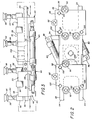
- Fig. 1 is an elevational view of a labeller formed in accordance with this invention.
- Fig. 2 is a rear elevational view of the labeller of Fig. 1 and shows further details thereof.
- Fig. 3 is a top plan view of the label carrier portion only of the labeller.
- Fig. 4 is an elevational view taken between an open mold and schematically shows how two labels are simultaneously placed within an upper mold half in accordance with this invention.
- Figs. 5-8 are schematic elevational views similar to Fig. 4 showing the sequence placing labels within cavities of an outer or upper dual cavity mold half.
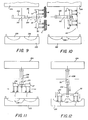
- Figs. 9-12 are schematic elevational views similar to Figs. 5-8, respectively, and shows the manner in which the labeller applies two labels to a dual cavity lower or inner mold half.
- the labeller 20 includes a support member best shown in Figs. 1-3 and identified by the numeral 22.
- the support member 22 includes a central mounting portion 24 and a pair of support legs 26, 28 extending in opposite directions.
- the support legs 26, 28, in turn, have slidably mounted thereon carriers 30, 32, respectively.
- each of the support legs 26, 28 are generally U-shaped in outline so as to provide a pair of spaced slide members 34, 36, respectively. This facilitates the sliding movement of the respective carriers 30, 32 thereon.
- the carriers 30, 32 are of like construction and each of the two carriers include a primary member in the form of a block 38 having a notched underside for having received therein the respective support leg 26 or 28.
- Each of the carriers 30, 32 also include a lower member 40 which is best shown in Fig. 1.
- Each lower member 40 includes a pair of longitudinal bars 42 which are secured to the underside of the block 38 by way of fasteners 44 to form a slide assembly.
- the bars 42 are joined together by a transverse member 46 which, in turn, carries a lower bracket or ear 48.
- the transverse member 46 is notched as at 50 to provide clearance above a portion of the ear 48 as is best shown in Fig. 1.
- a mounting plate 52 which has extending outwardly therefrom a bracket 54.
- the bracket 54 has coupled thereto by way of a fastener 56 a mounting bracket 58 of an extensible fluid motor 60.
- the fluid motor 60 also includes a piston rod 62 which carries a bifurcated fitting 64 which is pivotally connected to the ear 48 by way of a pivot pin 66.
- the support member 22 In order to limit outward movement of the carrier 30 on the support member 22, the support member 22 carries a pair of fixed stops 68 which are engageable by stop 70 carried by the carrier 30, as is best shown in Fig. 1.
- the other side of the support member 22 is provided with a mounting plate 72 which carries a bracket 74 to which there is pivotally connected by way of a pivot pin 76 a mounting ear 78 on the end of a second extensible fluid motor generally identified by the numeral 80.
- the fluid motor 80 includes a piston rod 82 which carries a bifurcated fitting 84 which is connected by way of a pivot pin 86 to the associated ear 48.
- the stroke of the fluid motor 80 is less than that of the fluid motor 60 as is the travel of the carrier 32 as compared to the carrier 30.
- the carrier 32 carries suitable stops 88 which are engageable with stops 90 carried by the support member 22 to limit the outward movement of the carrier 32.
- each of the blocks 38 carry mounting fittings 92 which, in turn, has extending therefrom a length of pipe 94 which carries a suction head 96 which may incorporate a suitable bellows 98.
- Each of the blocks 38 is provided with internal passages (not shown) which connect an inlet 100 to each of the fittings.
- the inlets 100 are connected to a vacuum source (not shown) by way of a conventional type of control (not shown).
- the central portion 24 of the support member 22 is offset as is best shown in Fig. 3 and is provided with a bore 102 which receives a piston rod 104 of an extensible fluid motor generally identified by the numeral 106 as is best shown in Fig. 4.
- the fluid motor 106 includes a cylinder 108 having a pivotal mount (not shown) mounting the fluid motor 106 for pivoting about an axis 110.
- the pivotal mount includes a control arm 112 which has connected thereto by way of a pivot pin 114 a bifurcated end 116 of a piston rod 118 of yet another extensible fluid motor 120.
- the labeller 20 is mounted with respect to open mold halves 122, 124.
- the mold halves 122, 124 form one mold of a plurality of molds of a blow molding machine wherein the molds are mounted in a ferris wheel like arrangement.
- the inner mold (mold 122) is stationary and the outer mold (mold 124) is radially movable between a closed position cooperating with the inner mold 122 and an open position as shown in Fig. 4.
- the mold halves 122, 124 move along a predetermined path of travel.
- each of the mold halves 122, 124 is part of a dual cavity mold with the cavities being identified by the numeral 126. It will be seen that the cavities 126 must be spaced apart within their respective mold halves and that the total width of labels L as they are being applied to the cavities 126 are such that they cannot be moved into the limited space between the open mold halves 122, 124, rotated into alignment with the cavities 126 and then moved into the cavities. The construction of the labeller 20 overcomes this deficiency.
- labels L are provided in stacks within a pair of side-by-side label magazines generally identified by the letter M.
- a lowermost one of the magazines M is positioned so that a label dispensed therefrom will be disposed only slightly above the face of the mold half 122.
- the construction of the magazines M is such that the spacing between labels L in two stacks is too great to enter in between the rotating mold halves 122, 124.
- the support member 22 when the labels are to be deposited into the cavities 126 of the outer mold half 124, the support member 22 is vertically disposed with the carrier 30 disposed uppermost. Further, the lower carrier 32 is positioned in horizontal alignment with the lower of the magazines M as is clearly shown in Fig. 4.
- the fluid motor 60 is actuated to move the carrier 30 upwardly into alignment with the labels L carried by the upper magazines M. This is schematically shown in Fig. 4.
- the fluid motor 60 is again actuated so as to move the carrier 30 down and thus move the upper labels L down to the position closely adjacent the lower labels L as is also shown in Fig. 4.
- the spacing of the labels L is now one which permits turning or rotation of the labeller to align the labels L with the cavities 126 as is schematically shown in Fig. 7.
- the label pickup is schematically shown in Fig. 5 while the movement of the upper label towards the lower label is clearly shown in Fig. 6.
- the labels L are brought into position generally opposing the outer mold 124, the labels L are closely adjacent one another and not aligned with the cavities 126.
- the fluid motors 60, 80 are then actuated as is schematically shown in Figs. 7 and 8 to move the labels L apart and into alignment with the cavities 126.
- the fluid motor 106 is then actuated to advance the carriers 30, 32 towards the respective cavities 126 and to position the labels within the respective cavities 126.
- the pickup heads 96 are suction heads and starting with the time that a label is to be picked up by the pickup heads 96, a vacuum is drawn in the pickup heads and this vacuum is maintained until the labels L are positioned within the respective cavities 126 at which time the vacuum is discontinued and, preferably, air under pressure is directed to the pickup heads 96 to force the labels against the surfaces of the cavities 126.
- the cavities 126 may have associated therewith suitable vacuum means for maintaining the labels L positioned therein.
- Figs. 9-12 are similar to Figs. 5-8, respectively, but relate to the placing of labels within the dual cavity inner mold half 122.
- the pivot axis 110 for the fluid motor 106 is closer to the inner mold half 122 in Figs. 5-8 while it is closer to the outer mold half 124 in Figs. 9-12.
- the position of the support member 22 has been rotated 180° in Fig. 9 from its position of Fig. 5 so that the carrier 30, which was previously uppermost, is now lowermost while the carrier 32 is disposed uppermost.
- the magazines M are disposed more closely adjacent the outermost mold half 124, in relationship the opposite of that shown in Fig. 4.
- the fluid motor 106 is rotated in a clockwise direction to apply the labels L as opposed to the counterclockwise direction shown in Fig. 6.
- the operation of the labeller 20 to apply the labels L to the inner mold half 122 is basically the same as that previously described with respect to the application of labels to the outer mold half 124.
- FIGs. 5-12 are schematic views and that while the fluid motor 106 is illustrated in each of these views, for purposes of clarity, the fluid motors 60, 80 and 120 have been omitted.
Landscapes
- Engineering & Computer Science (AREA)
- Manufacturing & Machinery (AREA)
- Mechanical Engineering (AREA)
- Blow-Moulding Or Thermoforming Of Plastics Or The Like (AREA)
- Moulds For Moulding Plastics Or The Like (AREA)
Priority Applications (2)
| Application Number | Priority Date | Filing Date | Title |
|---|---|---|---|
| US07/607,041 US5198247A (en) | 1990-10-31 | 1990-10-31 | In-mold labellers for a dual cavity mold |
| EP92311855A EP0604690A1 (fr) | 1990-10-31 | 1992-12-30 | Dispositif d'étiquetage dans le moule pour moules à double cavité |
Applications Claiming Priority (2)
| Application Number | Priority Date | Filing Date | Title |
|---|---|---|---|
| US07/607,041 US5198247A (en) | 1990-10-31 | 1990-10-31 | In-mold labellers for a dual cavity mold |
| EP92311855A EP0604690A1 (fr) | 1990-10-31 | 1992-12-30 | Dispositif d'étiquetage dans le moule pour moules à double cavité |
Publications (1)
| Publication Number | Publication Date |
|---|---|
| EP0604690A1 true EP0604690A1 (fr) | 1994-07-06 |
Family
ID=26132319
Family Applications (1)
| Application Number | Title | Priority Date | Filing Date |
|---|---|---|---|
| EP92311855A Ceased EP0604690A1 (fr) | 1990-10-31 | 1992-12-30 | Dispositif d'étiquetage dans le moule pour moules à double cavité |
Country Status (2)
| Country | Link |
|---|---|
| US (1) | US5198247A (fr) |
| EP (1) | EP0604690A1 (fr) |
Families Citing this family (11)
| Publication number | Priority date | Publication date | Assignee | Title |
|---|---|---|---|---|
| IT1260295B (it) * | 1992-11-13 | 1996-04-03 | Moreno Minghetti | Macchina ad elevata produzione per la termoformatura per soffiaggio di contenitori od altri corpi cavi, in materia termoplastica. |
| US5919498A (en) * | 1995-12-05 | 1999-07-06 | R & B Machine Tool Company | Apparatus for applying labels to blow-molded articles |
| US5908590A (en) * | 1995-12-28 | 1999-06-01 | Sekisui Plastics Co., Ltd. | Process and apparatus for manufacturing a foamed resin container with a label |
| US5690783A (en) * | 1997-01-15 | 1997-11-25 | Eastman Kodak Company | Mechanism for repositioning label applicator head before applying label to interior of carton |
| US6264876B1 (en) * | 1998-07-08 | 2001-07-24 | Thomas P. Ballay | In-mold labeling cylindrical bottles |
| DE60019767T2 (de) * | 1999-08-20 | 2006-03-09 | Fountain Technologies B.V. I.O. | Verfahren und vorrichtung zum herstellen von gegenständen und zum einbringen von etiketten in eine form |
| DE19952375A1 (de) * | 1999-10-30 | 2001-05-10 | Espera Werke Gmbh | Vorrichtung zum Anbringen von Haftetiketten auf Warenpackungen |
| NL1019324C2 (nl) * | 2001-11-07 | 2003-05-08 | Novem Internat B V | Werkwijze en inrichting voor het plaatsen van labels. |
| US20060070704A1 (en) * | 2004-10-06 | 2006-04-06 | Tropicana Products, Inc. | Vaccum support and transfer of flexible material |
| NL2005581C2 (nl) * | 2010-10-26 | 2012-04-27 | Polymac B V | Werkwijze en inrichting voor het aanbrengen van een etiket in een matrijs. |
| SE538284C2 (sv) * | 2014-08-11 | 2016-04-26 | Hl Inv Ab | Anordning och förfarande för hantering av etiketter i en IML-process |
Citations (3)
| Publication number | Priority date | Publication date | Assignee | Title |
|---|---|---|---|---|
| FR2389580A1 (fr) * | 1977-05-05 | 1978-12-01 | Heye Hermann | |
| EP0137588A1 (fr) * | 1983-07-19 | 1985-04-17 | Continental Plastic Containers, Inc. | Dispositif pour insérer des étiquettes |
| US4582474A (en) * | 1985-04-02 | 1986-04-15 | Plastipak Packaging, Inc. | In-mold label dispenser of blow molding machine |
Family Cites Families (7)
| Publication number | Priority date | Publication date | Assignee | Title |
|---|---|---|---|---|
| US4355967A (en) * | 1980-09-30 | 1982-10-26 | The Continental Group, Inc. | Label applying device |
| US4838776A (en) * | 1983-08-18 | 1989-06-13 | Hasl Siegfried C | Label transferring apparatus for blow molding machines |
| US4479644A (en) * | 1983-07-19 | 1984-10-30 | Continental Plastic Containers, Inc. | In-mold labeler |
| US4679997A (en) * | 1985-11-25 | 1987-07-14 | Owens-Illinois, Inc. | Apparatus for delivering labels to blow molds of a plastic container blowing machine and removing the blown containers with the labels thereon |
| US4917592A (en) * | 1988-03-31 | 1990-04-17 | Owens-Illinois Plastic Products, Inc. | Apparatus for applying labels to blow molded articles |
| KR950011145B1 (ko) * | 1988-06-27 | 1995-09-28 | 도요 세이깡 가부시끼가시야 | 로터리 블로우 성형기의 라벨 점착 장치 |
| US5026266A (en) * | 1988-12-16 | 1991-06-25 | Toppan Publishing Co., Ltd. | Label feeder for a mold for plastics moldings |
-
1990
- 1990-10-31 US US07/607,041 patent/US5198247A/en not_active Expired - Fee Related
-
1992
- 1992-12-30 EP EP92311855A patent/EP0604690A1/fr not_active Ceased
Patent Citations (3)
| Publication number | Priority date | Publication date | Assignee | Title |
|---|---|---|---|---|
| FR2389580A1 (fr) * | 1977-05-05 | 1978-12-01 | Heye Hermann | |
| EP0137588A1 (fr) * | 1983-07-19 | 1985-04-17 | Continental Plastic Containers, Inc. | Dispositif pour insérer des étiquettes |
| US4582474A (en) * | 1985-04-02 | 1986-04-15 | Plastipak Packaging, Inc. | In-mold label dispenser of blow molding machine |
Also Published As
| Publication number | Publication date |
|---|---|
| US5198247A (en) | 1993-03-30 |
Similar Documents
| Publication | Publication Date | Title |
|---|---|---|
| EP0343155B1 (fr) | Distributeur d'etiquettes dans le moule pour moulage par soufflage | |
| AU587805B2 (en) | In-mold label dispenser for plastic blow molding machine | |
| US5198247A (en) | In-mold labellers for a dual cavity mold | |
| AU645649B2 (en) | In-mold labeling apparatus with rotary label transfer and method | |
| JPS62500845A (ja) | グリッパ−・ヘッド | |
| CA1255468A (fr) | Debiteur d'etiquettes sous moule pour le moulage par soufflage | |
| CA2392583C (fr) | Etiquetage dans le moule en moulage par systeme rotatif | |
| CA2392581C (fr) | Systeme rotatif de moulage par soufflage de matieres plastiques permettant l'etiquetage dans le moule | |
| US6182940B1 (en) | Spacer for stacking glass plates, method for attaching the spacer to the glass plate and apparatus for attaching the spacer to the glass plate | |
| US4802832A (en) | In-mold labeling accessory for a blow molding machine | |
| EP0299953B1 (fr) | Distributeur d'etiquettes a l'interieur d'un moule pour machine de moulage par soufflage | |
| JPH03126520A (ja) | プラスチック吹込成形機の金型にラベルを施す装置および方法 | |
| US4721451A (en) | In-mold label dispenser for plastic blow molding | |
| US5256365A (en) | In-molding labeling method | |
| US4737098A (en) | In-mold labeling apparatus | |
| US4838776A (en) | Label transferring apparatus for blow molding machines | |
| US4769205A (en) | In-mold labeling method | |
| EP0471749B1 (fr) | Distributeur d'etiquettes dans le moule a un seul actuateur, pour tete de distribution et support d'etiquettes | |
| CA1234661A (fr) | Appareil de transfert d'etiquettes pour machines de moulage par soufflage | |
| CA2058205C (fr) | Appareil et methode de decoration dans le moule | |
| US6644647B2 (en) | Apparatus and method for transferring labels from a label magazine for in-mold labeling prior to blow molding | |
| US4944665A (en) | Rotary arm label transfer apparatus in combination with molding apparatus | |
| US4729731A (en) | Linear actuator for label transfer device | |
| WO1985004310A1 (fr) | Appareil de transfert d'etiquettes a bras rotatif et verin lineaire |
Legal Events
| Date | Code | Title | Description |
|---|---|---|---|
| PUAI | Public reference made under article 153(3) epc to a published international application that has entered the european phase |
Free format text: ORIGINAL CODE: 0009012 |
|
| AK | Designated contracting states |
Kind code of ref document: A1 Designated state(s): AT BE CH DE DK ES FR GB GR IE IT LI LU MC NL PT SE |
|
| 17P | Request for examination filed |
Effective date: 19940801 |
|
| 17Q | First examination report despatched |
Effective date: 19950620 |
|
| GRAG | Despatch of communication of intention to grant |
Free format text: ORIGINAL CODE: EPIDOS AGRA |
|
| STAA | Information on the status of an ep patent application or granted ep patent |
Free format text: STATUS: THE APPLICATION HAS BEEN REFUSED |
|
| 18R | Application refused |
Effective date: 19970208 |