EP0604811A2 - Procédé et dispositif pour la récupération de données dans un système de communication utilisant des rafales - Google Patents
Procédé et dispositif pour la récupération de données dans un système de communication utilisant des rafales Download PDFInfo
- Publication number
- EP0604811A2 EP0604811A2 EP93120028A EP93120028A EP0604811A2 EP 0604811 A2 EP0604811 A2 EP 0604811A2 EP 93120028 A EP93120028 A EP 93120028A EP 93120028 A EP93120028 A EP 93120028A EP 0604811 A2 EP0604811 A2 EP 0604811A2
- Authority
- EP
- European Patent Office
- Prior art keywords
- bit
- preamble
- data
- clocks
- clock
- Prior art date
- Legal status (The legal status is an assumption and is not a legal conclusion. Google has not performed a legal analysis and makes no representation as to the accuracy of the status listed.)
- Withdrawn
Links
Images
Classifications
-
- H—ELECTRICITY
- H04—ELECTRIC COMMUNICATION TECHNIQUE
- H04L—TRANSMISSION OF DIGITAL INFORMATION, e.g. TELEGRAPHIC COMMUNICATION
- H04L7/00—Arrangements for synchronising receiver with transmitter
- H04L7/04—Speed or phase control by synchronisation signals
- H04L7/041—Speed or phase control by synchronisation signals using special codes as synchronising signal
- H04L7/042—Detectors therefor, e.g. correlators, state machines
Definitions
- This invention refers to a method and a device for data recovery in burst mode communication systems, which include a preamble that contains a previously defined sequence and in which this preamble is digitized with a fixed number of samples per bit for subsequent processing to obtain the data and clock signals.
- This method is especially applicable to burst mode communication systems in which, for requirements of the system, it is desirable to synchronize the data clock in order to recover the data in a very short time.
- This article shows a block diagram of a fast bit synchronization circuit in which four bit rate clocks are generated with uniformly distributed phases and which are used for the sampling of the incoming data so that, subsequently, a detector circuit can determine which of the differently phased clocks best adapt to the incoming data.
- the operating principle is based, as shown in figure 6 of the article mentioned, on carrying out an exclusive-OR function with two consecutive samples to detect the transitions of the data.
- the results of the preceding operations are progressively stored in a register, decoding of which serves to select the clock with best phase.
- bit synchronism is achieved after several bit periods.
- the bursts must contain a preamble with a defined sequence of a certain number of bits, the first stage being to sample, with n samples per bit, the preamble corresponding to the received burst with the same number, n, of bit clocks obtained from a single master clock and which have different phases.
- This sampled preamble of the burst is correlated with a certain number of representations of the previous defined sequence of the preamble, sampled with the same number n of samples per bit, in which each representation is delayed a sample clock period with respect to the preceding one.
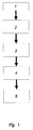
- the method of the invention is characterized in that the succession of steps shown in the flowchart of figure 1 in which, on block 1, which represents the preamble of the received burst, a sampling process 2 is carried out with n samples per bit, by means of n bit clocks with different phases, in order to proceed with a correlation 3 of this sampled burst preamble 1, with a set of digitized representations in order to obtain, in this way, the same number of correlation results as there are representations and then proceed to the decision 4 for the optimum phase clock, among the n available clocks, and of the first received data bit, based on which is the result with greatest correlation.
- regeneration 5 takes place of the received data sampled at the optimum moment, in accordance with the decision 4 taken in the previous stage.
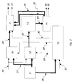
- the incoming data 22, that include a preamble with a defined sequence of m bits, are applied to a first digitizer 12 to which are also applied the n bit clocks 21 for digitizing of this preamble.
- a timing generator 15 that receives a burst start indication signal 27 and part of the n clocks 36, and that generates, in turn, a first control signal 28 to enable the first digitizer 12 during a time window in which the defined sequence of the burst preamble is expected.
- the digitized preamble 23 appears at the output of the first digitizer 12 for correlation in a multiple correlator 13 with a certain number of representations of the known sequence of the burst preamble, also sampled n times per bit and in which each representation is delayed one sample with respect to the preceding one.
- a selector 14 that decides, based on which of these is the largest, the optimum phase clock 25 for the subsequent regeneration of the received data.
- the selector 14 also generates an advance 34 or retard 35 signal of the burst preamble with respect to the central representation used in the multiple correlator 13 and a first data bit indication signal 33. These burst preamble advance 34 or retard 35 signals are activated, respectively, when the representation that produces the greatest correlation has been shifted a certain number of samples to the right or to the left because of a delay that is greater or lesser than that expected in the reception of the corresponding burst.
- This device also incorporates a second digitizer 16 that is enabled by a second control signal 29, generated by the timing generator 15, for digitizing the incoming data 22 with the n bit clocks 21, once the preamble has been excluded.
- the digitized data 26 coming from the second digitizer 16 are applied over an n-line parallel bus to an output control circuit 17 that also receives the indication of optimum phase clock 25 and the indication of the first data bit 33 coming from the selector 14, together with a third control signal 30 from the timing generator 15; all the foregoing being used to present at its output the recovered data clock 31 and those data sampled at the optimum instant 32.
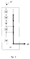
- figure 3 shows the composition of the generator 11 of the n clocks 21 with different phases, which is done by cascading n-1 delay stages 18, each one producing a delay equal to the bit clock period divided by n.
- the n clocks 21 are therefore the outputs of these n-1 delay stages 18 plus the input signal to the first stage 37 that comes from a bit master clock.
Landscapes
- Engineering & Computer Science (AREA)
- Computer Networks & Wireless Communication (AREA)
- Signal Processing (AREA)
- Synchronisation In Digital Transmission Systems (AREA)
- Dc Digital Transmission (AREA)
Applications Claiming Priority (2)
| Application Number | Priority Date | Filing Date | Title |
|---|---|---|---|
| ES09202649A ES2071554B1 (es) | 1992-12-30 | 1992-12-30 | Metodo y dispositivo de recuperacion de datos en sistemas de comunicacion a rafagas. |
| ES9202649 | 1992-12-30 |
Publications (2)
| Publication Number | Publication Date |
|---|---|
| EP0604811A2 true EP0604811A2 (fr) | 1994-07-06 |
| EP0604811A3 EP0604811A3 (en) | 1997-02-12 |
Family
ID=8279261
Family Applications (1)
| Application Number | Title | Priority Date | Filing Date |
|---|---|---|---|
| EP93120028A Withdrawn EP0604811A3 (en) | 1992-12-30 | 1993-12-11 | Method and device for data recovery in burst mode communication systems. |
Country Status (6)
| Country | Link |
|---|---|
| US (1) | US5479451A (fr) |
| EP (1) | EP0604811A3 (fr) |
| JP (1) | JPH077499A (fr) |
| AU (1) | AU670144B2 (fr) |
| CA (1) | CA2108799A1 (fr) |
| ES (1) | ES2071554B1 (fr) |
Cited By (3)
| Publication number | Priority date | Publication date | Assignee | Title |
|---|---|---|---|---|
| EP0577848A4 (en) * | 1992-01-29 | 1997-08-06 | Fujitsu Ltd | Circuit for detecting object signal from input signal |
| EP0809376A3 (fr) * | 1996-05-21 | 2002-09-04 | Nokia Corporation | Méthode de synchronisation d'un récepteur avec correction d'erreur d'horloge et de fréquence |
| EP1049286A3 (fr) * | 1999-04-28 | 2004-06-30 | Texas Instruments Incorporated | Synchronisation de trames à échantillonnage multiple |
Families Citing this family (13)
| Publication number | Priority date | Publication date | Assignee | Title |
|---|---|---|---|---|
| JPH0715744B2 (ja) * | 1985-08-13 | 1995-02-22 | 日立マクセル株式会社 | 磁気記録媒体 |
| US5652771A (en) * | 1995-01-04 | 1997-07-29 | Hughes Electronics | Time tracking based on a Taylor series of an expected signal |
| AU719844B2 (en) * | 1995-10-12 | 2000-05-18 | Next Level Communications | Burst mode preamble |
| GB2310116B (en) * | 1996-02-08 | 2000-06-07 | Nokia Mobile Phones Ltd | Method and apparatus for clock recovery |
| KR100193837B1 (ko) * | 1996-08-24 | 1999-06-15 | 윤종용 | 시분할다윈접속 디지탈 이동통신 시스템의 주파수 교정 버스트 검출방법 |
| US5864585A (en) | 1996-10-07 | 1999-01-26 | Erisman; David | Cosine segment communications system |
| US6498667B1 (en) | 1999-09-10 | 2002-12-24 | Quantum Bridge Communications, Inc. | Method and system for packet transmission over passive optical network |
| US6122335A (en) * | 1999-10-01 | 2000-09-19 | Quantum Bridge Communications, Inc. | Method and apparatus for fast burst mode data recovery |
| US6592272B1 (en) | 1999-10-22 | 2003-07-15 | Quantum Bridge Communications, Inc. | Burst mode transmission over multiple optical wavelengths |
| US6587500B1 (en) | 1999-12-17 | 2003-07-01 | Telefonaktiebolaget Lm Ericsson (Publ) | Symbol sampling time settlement of a hard decision radio receiver |
| US6990123B1 (en) | 2000-01-24 | 2006-01-24 | Quantum Bridge Communications Inc. | Method and apparatus for redundant transmission over TDMA optical networks |
| KR100839488B1 (ko) * | 2006-08-30 | 2008-06-19 | 삼성전자주식회사 | 기준 클럭이 불필요한 클럭 데이터 복원 회로 |
| KR102472946B1 (ko) * | 2016-02-26 | 2022-12-05 | 에스케이하이닉스 주식회사 | 신호 복원 회로 |
Family Cites Families (10)
| Publication number | Priority date | Publication date | Assignee | Title |
|---|---|---|---|---|
| US4660164A (en) * | 1983-12-05 | 1987-04-21 | The United States Of America As Represented By The Secretary Of The Navy | Multiplexed digital correlator |
| US4918406A (en) * | 1986-12-31 | 1990-04-17 | Raytheon Company | Timing recovery scheme for burst communication systems having a VCO with injection locking circuitry |
| GB2206267B (en) * | 1987-06-24 | 1991-09-25 | Plessey Co Plc | Novel correlator for synchronisation detection |
| US4829543A (en) * | 1987-12-04 | 1989-05-09 | Motorola, Inc. | Phase-coherent TDMA quadrature receiver for multipath fading channels |
| JPH0716206B2 (ja) * | 1988-08-05 | 1995-02-22 | 日本電気株式会社 | 信号検出器 |
| CA2018855C (fr) * | 1989-06-14 | 1993-09-21 | Shousei Yoshida | Demodulateur de salves a circuits d'extraction de porteuses et de signaux d'horloge incorpores a une sequence de symboles alternatifs |
| US4959846A (en) * | 1989-09-11 | 1990-09-25 | Raynet Corporation | Clock recovery apparatus including a clock frequency adjuster |
| DE4038561A1 (de) * | 1990-10-02 | 1992-04-09 | F & O Elektronic Systems Gmbh | Verfahren zur getakteten korrelations- und signalverarbeitung mittels risc-prozessor fuer drahtlose empfaenger in von sendern ausgestrahlten digitalen rahmennetzen, mobilfunknetzen und gleichwertigen einrichtungen und vorrichtung hierzu |
| EP0520127A1 (fr) * | 1991-06-28 | 1992-12-30 | ALCATEL BELL Naamloze Vennootschap | Circuit numérique de synchronisation utilisant une ligne de rétard accordée et branchée |
| US5347548A (en) * | 1992-06-19 | 1994-09-13 | Motorola Inc. | Circuit for simultaneous recovery of bit clock and frame synchronization |
-
1992
- 1992-12-30 ES ES09202649A patent/ES2071554B1/es not_active Expired - Lifetime
-
1993
- 1993-10-20 CA CA002108799A patent/CA2108799A1/fr not_active Abandoned
- 1993-11-29 US US08/158,708 patent/US5479451A/en not_active Expired - Fee Related
- 1993-12-11 EP EP93120028A patent/EP0604811A3/en not_active Withdrawn
- 1993-12-13 AU AU52376/93A patent/AU670144B2/en not_active Ceased
- 1993-12-21 JP JP32266993A patent/JPH077499A/ja active Pending
Cited By (3)
| Publication number | Priority date | Publication date | Assignee | Title |
|---|---|---|---|---|
| EP0577848A4 (en) * | 1992-01-29 | 1997-08-06 | Fujitsu Ltd | Circuit for detecting object signal from input signal |
| EP0809376A3 (fr) * | 1996-05-21 | 2002-09-04 | Nokia Corporation | Méthode de synchronisation d'un récepteur avec correction d'erreur d'horloge et de fréquence |
| EP1049286A3 (fr) * | 1999-04-28 | 2004-06-30 | Texas Instruments Incorporated | Synchronisation de trames à échantillonnage multiple |
Also Published As
| Publication number | Publication date |
|---|---|
| JPH077499A (ja) | 1995-01-10 |
| EP0604811A3 (en) | 1997-02-12 |
| ES2071554A1 (es) | 1995-06-16 |
| US5479451A (en) | 1995-12-26 |
| AU5237693A (en) | 1994-07-14 |
| AU670144B2 (en) | 1996-07-04 |
| ES2071554B1 (es) | 1996-01-16 |
| CA2108799A1 (fr) | 1994-07-01 |
Similar Documents
| Publication | Publication Date | Title |
|---|---|---|
| US5479451A (en) | Method and device for data recovery in burst mode communication system | |
| US5414730A (en) | Asynchronous samples data demodulation system | |
| US4418393A (en) | Matched filter spread spectrum code recovery apparatus | |
| US4881059A (en) | Manchester code receiver | |
| US4740962A (en) | Synchronizer for time division multiplexed data | |
| US5654991A (en) | Fast acquisition bit timing loop method and apparatus | |
| US5495509A (en) | High processing gain acquisition and demodulation apparatus | |
| US5379323A (en) | DQPSK delay detection circuit | |
| US5267264A (en) | Synchronization and matching method for a binary baseband transmission system | |
| US4606050A (en) | System for detecting and recovering a transmitted signal | |
| US6263011B1 (en) | Receiver for spread spectrum communication system capable of shortening acquisition time | |
| SE516144C2 (sv) | Tidssynkronisering av en mottagare i ett digitalt radiotelefonsystem | |
| US5802121A (en) | Synchronization device for digital communications | |
| US6219345B1 (en) | Timing estimation in mobile communication systems using parabolic interpolator | |
| US6130906A (en) | Parallel code matched filter | |
| CN1197313C (zh) | 用于对移动无线信道的信道冲击响应进行估值的方法 | |
| AU592935B2 (en) | An arrangement for fast frame synchronization | |
| US5689524A (en) | PN code synchronizing method and transmitter and receiver in spread spectrum communication systems | |
| JP2003188769A (ja) | 同期捕捉方法および装置 | |
| WO1999013586A1 (fr) | Systeme et procede permettant la conversion entre un bus mrt a plusieurs bits et un bus mrt a un seul bit par le biais de logique numerique | |
| JP2947074B2 (ja) | フレーム同期検出回路 | |
| US4352194A (en) | System and method for frequency discrimination | |
| US4542504A (en) | Shared data receiver | |
| US7643535B1 (en) | Compatible preparation and detection of preambles of direct sequence spread spectrum (DSSS) and narrow band signals | |
| GB2206267A (en) | Correlator for synchronisation detection |
Legal Events
| Date | Code | Title | Description |
|---|---|---|---|
| PUAI | Public reference made under article 153(3) epc to a published international application that has entered the european phase |
Free format text: ORIGINAL CODE: 0009012 |
|
| AK | Designated contracting states |
Kind code of ref document: A2 Designated state(s): BE DE FR GB IT NL SE |
|
| PUAL | Search report despatched |
Free format text: ORIGINAL CODE: 0009013 |
|
| AK | Designated contracting states |
Kind code of ref document: A3 Designated state(s): BE DE FR GB IT NL SE |
|
| 17P | Request for examination filed |
Effective date: 19970723 |
|
| 17Q | First examination report despatched |
Effective date: 19990423 |
|
| STAA | Information on the status of an ep patent application or granted ep patent |
Free format text: STATUS: THE APPLICATION IS DEEMED TO BE WITHDRAWN |
|
| 18D | Application deemed to be withdrawn |
Effective date: 20000310 |