EP0605216B1 - Antriebsteuerung mit Normalisierung eines Tintenstrahldruckkopfes - Google Patents
Antriebsteuerung mit Normalisierung eines Tintenstrahldruckkopfes Download PDFInfo
- Publication number
- EP0605216B1 EP0605216B1 EP93310497A EP93310497A EP0605216B1 EP 0605216 B1 EP0605216 B1 EP 0605216B1 EP 93310497 A EP93310497 A EP 93310497A EP 93310497 A EP93310497 A EP 93310497A EP 0605216 B1 EP0605216 B1 EP 0605216B1
- Authority
- EP
- European Patent Office
- Prior art keywords
- control signal
- value
- test
- control
- marking
- Prior art date
- Legal status (The legal status is an assumption and is not a legal conclusion. Google has not performed a legal analysis and makes no representation as to the accuracy of the status listed.)
- Expired - Lifetime
Links
- 238000010606 normalization Methods 0.000 title description 21
- 238000012360 testing method Methods 0.000 claims description 69
- 238000000034 method Methods 0.000 claims description 28
- 230000006870 function Effects 0.000 claims description 7
- 230000001419 dependent effect Effects 0.000 claims description 4
- 230000004044 response Effects 0.000 claims description 3
- 230000007423 decrease Effects 0.000 claims description 2
- 230000007704 transition Effects 0.000 claims 8
- 239000003086 colorant Substances 0.000 claims 3
- 239000012530 fluid Substances 0.000 claims 1
- 238000004519 manufacturing process Methods 0.000 description 7
- 239000000463 material Substances 0.000 description 6
- 238000005259 measurement Methods 0.000 description 3
- 238000012986 modification Methods 0.000 description 3
- 230000004048 modification Effects 0.000 description 3
- 230000003287 optical effect Effects 0.000 description 3
- 230000008878 coupling Effects 0.000 description 2
- 238000010168 coupling process Methods 0.000 description 2
- 238000005859 coupling reaction Methods 0.000 description 2
- 238000003384 imaging method Methods 0.000 description 2
- 230000000694 effects Effects 0.000 description 1
- RDYMFSUJUZBWLH-UHFFFAOYSA-N endosulfan Chemical compound C12COS(=O)OCC2C2(Cl)C(Cl)=C(Cl)C1(Cl)C2(Cl)Cl RDYMFSUJUZBWLH-UHFFFAOYSA-N 0.000 description 1
- 210000003127 knee Anatomy 0.000 description 1
- 238000012886 linear function Methods 0.000 description 1
- 239000011159 matrix material Substances 0.000 description 1
- 230000005499 meniscus Effects 0.000 description 1
- 230000000630 rising effect Effects 0.000 description 1
- 238000012163 sequencing technique Methods 0.000 description 1
- 238000012546 transfer Methods 0.000 description 1
Images

Classifications
-
- B—PERFORMING OPERATIONS; TRANSPORTING
- B41—PRINTING; LINING MACHINES; TYPEWRITERS; STAMPS
- B41J—TYPEWRITERS; SELECTIVE PRINTING MECHANISMS, i.e. MECHANISMS PRINTING OTHERWISE THAN FROM A FORME; CORRECTION OF TYPOGRAPHICAL ERRORS
- B41J2/00—Typewriters or selective printing mechanisms characterised by the printing or marking process for which they are designed
- B41J2/005—Typewriters or selective printing mechanisms characterised by the printing or marking process for which they are designed characterised by bringing liquid or particles selectively into contact with a printing material
- B41J2/01—Ink jet
- B41J2/015—Ink jet characterised by the jet generation process
- B41J2/04—Ink jet characterised by the jet generation process generating single droplets or particles on demand
- B41J2/045—Ink jet characterised by the jet generation process generating single droplets or particles on demand by pressure, e.g. electromechanical transducers
- B41J2/04501—Control methods or devices therefor, e.g. driver circuits, control circuits
- B41J2/04506—Control methods or devices therefor, e.g. driver circuits, control circuits aiming at correcting manufacturing tolerances
-
- B—PERFORMING OPERATIONS; TRANSPORTING
- B41—PRINTING; LINING MACHINES; TYPEWRITERS; STAMPS
- B41J—TYPEWRITERS; SELECTIVE PRINTING MECHANISMS, i.e. MECHANISMS PRINTING OTHERWISE THAN FROM A FORME; CORRECTION OF TYPOGRAPHICAL ERRORS
- B41J2/00—Typewriters or selective printing mechanisms characterised by the printing or marking process for which they are designed
- B41J2/005—Typewriters or selective printing mechanisms characterised by the printing or marking process for which they are designed characterised by bringing liquid or particles selectively into contact with a printing material
- B41J2/01—Ink jet
- B41J2/015—Ink jet characterised by the jet generation process
- B41J2/04—Ink jet characterised by the jet generation process generating single droplets or particles on demand
- B41J2/045—Ink jet characterised by the jet generation process generating single droplets or particles on demand by pressure, e.g. electromechanical transducers
- B41J2/04501—Control methods or devices therefor, e.g. driver circuits, control circuits
- B41J2/04581—Control methods or devices therefor, e.g. driver circuits, control circuits controlling heads based on piezoelectric elements
-
- B—PERFORMING OPERATIONS; TRANSPORTING
- B41—PRINTING; LINING MACHINES; TYPEWRITERS; STAMPS
- B41J—TYPEWRITERS; SELECTIVE PRINTING MECHANISMS, i.e. MECHANISMS PRINTING OTHERWISE THAN FROM A FORME; CORRECTION OF TYPOGRAPHICAL ERRORS
- B41J2/00—Typewriters or selective printing mechanisms characterised by the printing or marking process for which they are designed
- B41J2/005—Typewriters or selective printing mechanisms characterised by the printing or marking process for which they are designed characterised by bringing liquid or particles selectively into contact with a printing material
- B41J2/01—Ink jet
- B41J2/015—Ink jet characterised by the jet generation process
- B41J2/04—Ink jet characterised by the jet generation process generating single droplets or particles on demand
- B41J2/045—Ink jet characterised by the jet generation process generating single droplets or particles on demand by pressure, e.g. electromechanical transducers
- B41J2/04501—Control methods or devices therefor, e.g. driver circuits, control circuits
- B41J2/04588—Control methods or devices therefor, e.g. driver circuits, control circuits using a specific waveform
-
- B—PERFORMING OPERATIONS; TRANSPORTING
- B41—PRINTING; LINING MACHINES; TYPEWRITERS; STAMPS
- B41J—TYPEWRITERS; SELECTIVE PRINTING MECHANISMS, i.e. MECHANISMS PRINTING OTHERWISE THAN FROM A FORME; CORRECTION OF TYPOGRAPHICAL ERRORS
- B41J2/00—Typewriters or selective printing mechanisms characterised by the printing or marking process for which they are designed
- B41J2/005—Typewriters or selective printing mechanisms characterised by the printing or marking process for which they are designed characterised by bringing liquid or particles selectively into contact with a printing material
- B41J2/01—Ink jet
- B41J2/07—Ink jet characterised by jet control
- B41J2/125—Sensors, e.g. deflection sensors
-
- B—PERFORMING OPERATIONS; TRANSPORTING
- B41—PRINTING; LINING MACHINES; TYPEWRITERS; STAMPS
- B41J—TYPEWRITERS; SELECTIVE PRINTING MECHANISMS, i.e. MECHANISMS PRINTING OTHERWISE THAN FROM A FORME; CORRECTION OF TYPOGRAPHICAL ERRORS
- B41J29/00—Details of, or accessories for, typewriters or selective printing mechanisms not otherwise provided for
- B41J29/38—Drives, motors, controls or automatic cut-off devices for the entire printing mechanism
- B41J29/393—Devices for controlling or analysing the entire machine ; Controlling or analysing mechanical parameters involving printing of test patterns
Definitions
- This invention relates to ink jet printers and, more specifically, to normalizing the ink jets of a multi-orificed ink jet print head in order to obtain optimum performance from each jet of the print head.
- U. S. Patent 5,124,716 discloses a multi-orifice ink jet print head for ejecting ink drops onto a print medium, such as paper.
- the multi-orificed ink jet print head 25 is shown with associated elements in FIG. 1.
- An acoustic driver such as a piezoelectric transducer 32, is coupled to a diaphragm 34 for ejecting ink drops from an ink chamber 12, through a nozzle orifice 18, and onto a print medium 19.
- the piezoelectric transducer 32 comprises first and second conductive electrodes separated by a layer of insulating piezoelectric material.
- a control signal provided by a signal source 36 is applied to the transducer and the diaphragm 34 is displaced according to the voltage of the control signal.
- FIG. 2 shows a known unnormalized waveform of a control signal that may be provided by the signal source 56 for driving the piezoelectric transducer 32.
- the signal has a positive pulse of +Vo volts which lasts for about 5 ⁇ s and then returns to 0 volts.
- the signal remains at 0 volts for a period of time T1.
- a negative pulse of -Vo volts follows the period T1 and lasts for a second period T2 before returning to 0 volts.
- the piezoelectric transducer displaces the diaphragm away from the cavity interior, and ink from reservoir 14 is drawn into the cavity 12.
- the diaphragm is displaced for compressing the cavity and an ink drop is ejected from the orifice 18 onto the print medium 19.
- the print head 25 shuttles back and forth along the X-axis parallel to the plane of the print medium surface and the print medium advances along the Y-axis perpendicular to the X-axis while the jets of the print head eject drops onto the print medium.
- the quality of the resulting image depends upon the size and velocity of the drops produced by each jet of the array of jets of the print head. Drop size affects the color density of an image while velocity affects the placement of dots with respect to other dots in the image.
- each jet of the print head performs similarly to the other jets of the print head and each print head is manufactured with optimum parameters for ejecting ink. However, because of limited controls during manufacturing, performance variations exist.
- U.S. Patent 5,212,497 to Stanley et al. discloses a normalization technique wherein the drop ejection velocity of a jet is monitored by using a strobe imaging device to strobe ejected drops while adjusting the attenuation of the output signal provided by a signal source to produce the control signal applied to the jet's piezoelectric transducer.
- changing the amplitude of the control signal V cntrl changes the amount by which the acoustic driver 32 displaces the diaphragm 34 of the ink jet and thus affects drop ejection velocity.
- the control signal received by the piezoelectric transducer is controlled by adjusting a potentiometer R POT , which contributes to the series resistance (R POT + R SA ) of a divider network 36.
- R POT the series resistance
- R SA the series resistor
- the resistor trim normalization technique requires a significant amount of time for performing the normalization steps for all of the jets of the multiple-jet-array print head.
- the divider network dissipates power when attenuating the control signal and therefore consumes extra energy when used to attenuate the control signal and affect jet performance.
- a method of normalizing performance of an image forming marking element having an adjustable operating parameter wherein a quantifiable performance characteristic of the marking element depends on the value of the parameter.
- the method comprises the steps of operating the marking element with the operating parameter set to at least one test value and quantifying a value of said performance characteristic of the marking element, calculating a value of the operating parameter based on a desired value of said performance characteristic, said at least one test value of the operating parameter, and said value of the performance characteristic, and adjusting the operating parameter to its calculated value.
- This normalization may be done electronically or manually.
- a method of characterizing relative performance characteristics of an array of at least two image forming marking elements, each having an adjustable operating parameter comprises the steps of forming a test image with each marking element of the array with the operating parameter of each marking element set to at least one predetermined value, measuring a quality of each test image representative of each marking element, and quantifying a relative performance characteristic according to the differences in measured qualities between test images representative of the marking elements.
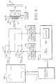
- FIG. 4 shows a signal source 56 generating two signals Vpp and Vss.
- Vpp is a positive going pulse train, with one pulse for each time any of the jets in the print head could need to eject ink.
- Vss is a negative going pulse train, with a single negative pulse following a fixed delay after the end of each positive Vpp pulse.
- For each jet there is a FET switch 70 connecting Vpp to V cntrl which drives the piezoelectric transducer 32 for that jet.
- FET switch 72 connecting Vss to V cntrl for that jet.
- Diodes 71 and 73 are connected across FET switches 70 and 72 respectively.
- the FET switches 70 and 72 are controlled from jet logic 76 through level translators 74 and 75 respectively.
- the level translators convert the standard 0 to 5 volt logic levels from jet logic 76 to the appropriate levels for driving the gates of FET's 70 and 72.
- Latch 82 within jet logic 76 holds the normalization value in a memory location for that jet.
- Blocks 70 through 76 are replicated once for each jet.
- control logic 77 sends timing, sequencing, and data signals to signal source 56 and to control logic 77. There may be more than one control logic block 77 for a print head, but typically each control logic block 77 will drive multiple jet logic blocks 76 and therefore control multiple jets.
- V cntrl the piezoelectric transducer driving voltage, for a given jet is controlled as follows: During the idle times between Vpp and Vss pulses, FET switch 72 is left on to keep V cntrl at zero volts. Since Vpp and Vss are both at zero volts in between pulses, either or both of the FET switches 70 and 72 could be turned on. (Even if neither of the FET switches 70 and 72 were on, V cntrl would remain near zero volts because of diodes 71 and 73.) If the jet is not to fire during a Vpp and Vss pulse pair, then FET switch 70 is kept off during the Vpp pulse and FET switch 72 is kept off during the Vss pulse.
- the opposite FET switch (72 during the Vpp pulse and 70 during the Vss pulse) may be turned on to help maintain zero volts on V cntrl . If the jet is to fire during a Vpp and Vss pulse pair, then FET switch 72 is kept off during the Vpp pulse and FET switch 70 is kept off during the Vss pulse. FET switch 70 is turned on before the Vpp pulse starts and is turned off during the rising edge of the Vpp pulse.
- the turn-off time is a function of the value stored in latch 82 within jet logic 76. The larger the value in latch 82, the later FET switch 70 is turned off, and therefore the higher voltage on V cntrl at the time it is turned off.
- V cntrl Since the piezoelectric transducer 32 presents a mostly capacitive load on V cntrl , the voltage on V cntrl will substantially maintain the voltage it had at the time FET switch 70 turned off. As Vpp ramps back down to zero volts at the end of its pulse, diode 71 will conduct to pull V cntrl back down near zero.
- the Vss pulse is handled similarly. Before the start of the Vss pulse, FET switch 72 is turned on. It is turned off during the leading (falling) edge of the Vss pulse at a time determined by the value in latch 82. It should be noted that a different latch could be used if separate control of the positive and negative pulse amplitudes is required.
- each leading edge of each Vpp and Vss pulse decreases at a knee part way through the leading edge. This allows a given time resolution for turning off FET switches 70 and 72 to result in finer voltage resolution on V cntrl .
- each jet within a print head has its associated jet logic 76 and latch 82, each jet can be driven with a different V cntrl amplitude by storing different values in each of the latches 82. If the values stored in latches 82 are selected such that each jet performs close to an optimum operation point, then the print head can be normalized with this drive method.
- latches 82 When generating the normalization data, latches 82 are loaded with a predetermined test value or values, and the desired characteristics of the jet are measured. The best value, or an approximation of that value, for latch 82 for each jet is determined from the measured characteristics, and this data is stored in non-volatile memory within the printer or head. When the printer is operated, the data from this non-volatile memory is loaded into latches 82 to cause each jet to be driven with near its optimum voltage level. Alternatively, latches 82 could be the non-volatile memory avoiding the loading step each time the printer is turned on or used.
- normalization is effected by adjusting dot size to produce a desired color density.
- Color density may be measured by comparing the intensity of light reflected by a test image with the intensity of incident light.
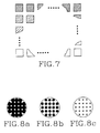
- the intensity of light reflected by the print medium bearing the test image depends on the proportion of the area of the print medium that remains exposed. This proportion is dependent on the imaged pattern and characteristics of the printer. For a nominal 25% fill shown in FIG. 8, the desired actual test image area coverage is at least ⁇ /8 or about 39%.
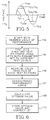
- FIG. 6 shows a flow chart for explaining the one particular normalization mode.
- the normalization mode has a primary objective of normalizing the jet for ejecting ink drops of a given drop size, so that the jet provides a desired color density when used to produce an image on the print medium.
- a desired color density is defined.
- a servo controller simultaneously controls the position of the print head 25 and the printing medium 19 while ejecting drops from the different jets of the multi-jet-array print head onto the print medium in order to create the test images as shown in FIG. 7.
- the jets are each tested at various test control values during the production of these test images.
- a first set of test patterns is made with each jet set to a first test control value provided by a normalization controller (not shown), whereupon a new test control value is stored in each of the latches and a new set of test patterns is generated on the print medium. This may be repeated for third and fourth or more test control values, dependent upon the shape of the characteristic curve.
- the print medium bears an array of test images wherein each test image represents one jet tested with its particular parameter set to a particular test control value.
- FIGS. 8a, 8b and 8c Enlarged views of FIG. 7 are shown in FIGS. 8a, 8b and 8c.
- FIG. 8b When the ink drops are the correct size, FIG. 8b, they occupy the desired percentage of the area of the test image.
- FIG. 8a When the ink drops ejected by the jet are too large, FIG. 8a, the dots occupy a greater proportion of the test image area and the test image produces a low intensity of reflected light.
- FIG. 8c the dots occupy a lesser proportion of the test image area and the intensity of light reflected is higher.
- the different test control values used during normalization can cover a sufficient range that at least one test image has a fill ratio greater than the desired percentage and at least one has a fill ratio less than the desired percentage.
- each test image of the print medium is examined by an optical scanning device, for example a Hewlett-Packard Scanner Jet IIc trade mark scanner or a JX 450 trade mark scanner from Sharp Electronics, Inc., for obtaining its color density.
- the color density is determined according to a reflection index, which is a ratio of an average reflected light intensity received from the test image in proportion to an incident light intensity as projected onto the test image.
- a characteristic curve is then derived in step 107 which defines a "color density versus test control value" relationship.
- step 108 an optimum control value is determined for each jet according to the characteristic curve, the test results, test control values of the jet and the desired image color density specified in step 102.
- the optimum control values are written (in step 110) into previously assigned non-volatile memory locations of, for example, a printer controller (not shown), by an appropriate apparatus, such as a CPU (not shown).
- the optimum control values are read from the memory array and the control latch 82 of each jet is loaded with its optimum control value. With the print head thus normalized, the ink jet printer will produce images of substantially ideal color density.
- a nominal performance curve for a nominal jet may be obtained by collecting a number of test data points, from a number of different jets, from a number of different manufacturing lots, which are tested over a wide range of test control values.
- the nominal curve is generated from a greater number of control values than would normally be used afterwards for normalizing a single jet as described with reference to FIG. 6.
- the nominal curve may then be adapted to each particular jet by using a scaling factor.
- the scaling factor is obtained according to the unique test results of each jet tested at the given test control values.
- the number of test control values used is only that which is necessary for obtaining the scaling factor and might be only two or three, or could be as few as one.
- the nominal curve is then scaled to produce a characteristic curve for the particular jet.
- An optimum control value that produces the desired image color density is then obtained using this characteristic curve for the individual jet. If necessary, an offset could be employed in place of or in conjunction with the scaling factor.
- a mathematical relationship can be used for characterizing the "color density versus control test value" relationship.
- the mathematical relationship may be a polynomial equation with the order of the polynomial being less than the number of test control values used during normalization, even as simple as a linear equation, from which the optimum control value would be extrapolated or interpolated.
- the coefficients taken from either the simple linear equation or the polynomial equation characterize the tested jets.
- the jet might be tested by ejecting an ink drop and making a measurement of the projection path of the ejected ink drop.
- the jet's projection path would be tested according to different control test values. Based on the test results, an optimum control value would be calculated for providing an optimum ink drop projection path.
- Measurements need not be limited to quantifying parameters of a printed image on a print medium.
- the measurement might employ the strobe technique as used in the resistor trim normalization method described above to collect at least one performance characteristic value of the image forming marking element when driven at least one test control value.
- the strobe technique described above could also be used in its entirety to determine the necessary drive voltage for each jet to obtain the desired performance characteristics. The drive voltage is then used to determine the control values to feed to the multiplicity of latches 82 to normalize the performance of the print head.
- Desired control or drive voltages can also be obtained by scanning the optical density of the test image. These voltages can then be used to calculate the required resistances to laser trim the resistors integral to print heads, such as those utilized in the Phaser III color printers trade mark sold by Tektronix, Inc.
- adjustable operating parameters discussed herein with regard to controlling the normalization of a print head include, but are not limited to, voltage, pulse width, delay time between pulses, and the rise and fall time of the pulses.
- the method can also be used to adjust more than one of these parameters by generating test images, for example, with each parameter independently varied while the others remain constant.
- quantifiable parameters discussed herein for controlling the print head normalization can include, but are not limited to, dot size, drop size, ejection velocity, drop time to target or receiving medium, dot placement, optical density, drop break off time, variation of drop size or velocity as a function of drop ejection frequency, peak negative pressure within the jet, PZT diaphragm deflection and ink meniscus resonance amplitude.
- time at which the FET switches 70 and 72 turn off need not be a linear function of the data value in latch 82.
- the latch value to turn-off time function could be modified to compensate for non-linearities in the leading edge ramp of Vss and Vpp, and/or for non linearities in the ink jet performance curve.
- the invention is not limited to the marking element being an ink jet, but is applicable also to the marking element for a bubble-jet printer, thermal transfer wax printer, or a dot matrix printer. Normalization also might involve determining different optimum control values for the positive and negative pulses, in which case the latch 82 could be used for positive pulses and a different latch (not shown) could be used for negative pulses.
Landscapes
- Ink Jet (AREA)
- Particle Formation And Scattering Control In Inkjet Printers (AREA)
- Dot-Matrix Printers And Others (AREA)
Claims (22)
- Verfahren zum Markieren eines Druckmediums (19) mit den folgenden Schritten:Betätigen eines Markierungselements (25) zum Auftragen eines Markierungsmediums auf das Druckmedium, wobei die Leistung des Markierungselements abhängig von einem optimalen Standard in Form eines Wertes eines meßbaren Leistungsparameters quantitativ bestimmbar ist;Betätigen eines Steuersignalmittels, das mit dem Markierungselement verbunden ist, um ein Steuersignal an das Markierungselement zu liefern, wobei das Markierungselement durch das Steuersignal aktiviert wird und der Leistungsparameter von der Amplitude des Steuersignals abhängig ist;Speichern eines bestimmten Steuerwertes in einem Signalspeicher (82) des Steuersignalmittels; undBestimmen der Amplitude des Steuersignals durch Betätigen des Steuersignalmittels in Abhängigkeit vom Steuerwert;
dadurch gekennzeichnet, daß die Betätigung des Steuersignalmittels die folgenden Schritte umfaßt:Eingabe eines Eingabesignals mit zumindest einem Übergang mit begrenzter Anstiegsgeschwindigkeit in eine Schaltvorrichtung (70, 72), und Aktivieren der Schaltvorrichtung zum Erzeugen des Steuersignals als Funktion des Steuerwerts durch selektives Verbinden des Eingabesignals mit dem Markierungselement und Trennen vom Markierungselement zu einem vom Steuerwert abhängigen Zeitpunkt, wobei die Amplitude des Steuersignals von dem Steuerwert und der Anstiegsgeschwindigkeit abhängig ist. - Verfahren nach Anspruch 1, bei dem das Eingabesignal einen Impuls umfaßt, der einen ersten Übergang von einem ersten Spannungspegel bis zu einer Spitzenspannung, vom Ende des ersten Übergangs an eine flache Spitzenspannung, und von der Spitzenspannung zum ersten Spannungspegel einen zweiten Übergang aufweist, und bei dem das Steuersignal so erzeugt wird, daß es gleich oder schwächer als das Eingabesignal ist, bei einem Spannungspegel, der dem Steuerwert entspricht.
- Verfahren nach Anspruch 2, bei dem das Eingabesignal weiterhin einen zweiten Impuls entgegengesetzter Polarität zum ersten Impuls aufweist sowie einen ersten Übergang vom ersten Spannungspegel zu einer Spitzenspannung entgegengesetzter Polarität, weiterhin eine flache Spitzenspannung vom Ende des ersten Übergangs an und einen zweiten Übergang von der Spitzenspannung entgegengesetzter Polarität zum ersten Spannungspegel.
- Verfahren nach einem der vorangehenden Ansprüche, bei dem das Markierungselement ein Ausstoßelement eines Tintenstrahldruckkopfes ist und bei dem das Steuersignal an einen Treiber (32) des Ausstoßelements angelegt wird, wodurch das Ausstoßelement gemäß dem Steuersignal Flüssigkeit ausstößt.
- Verfahren nach einem der vorangehenden Ansprüche, das einen Normalisierungsschritt einschließt, in dem der in dem Signalspeicher zu speichernde Steuerwert bestimmt wird, und das die folgenden Schritte umfaßt:(a) Betätigen des Markierungselements mit einem Teststeuerwert im Signalspeicher und quantitative Bestimmung eines entsprechenden Testwerts des Leistungsparameters des Markierungselements;(b) Berechnen des auf einem gewünschten Wert basierenden Steuerwerts, des Teststeuerwerts und des entsprechenden Testwerts des Leistungsparameters; und(c) Speichern des so berechneten Steuerwerts in dem Signalspeicher.
- Verfahren nach Anspruch 5, das den folgenden, zwischen den Schritten (a) und (b) durchzuführenden Schritt umfaßt, nämlich das Betätigen des Markierungselements mit zumindest einem anderen Teststeuerwert in dem Signalspeicher und quantitative Bestimmung zumindest eines anderen Testwertes des Leistungsparameters, wobei Schritt (b) das Berechnen des Steuerwertes auf der Basis des gewünschten Leistungsparameterwertes, der Teststeuerwerte und der entsprechenden quantitativ bestimmten Testwerte des Leistungsparameters umfaßt.
- Verfahren nach einem der Ansprüche 5 oder 6, bei dem das Markierungselement ein Markierungselement eines Druckkopfes ist, das eine Anordnung von M Markierungselementen aufweist, und das Verfahren das Durchführen der Schritte (a) bis (c) für jedes der M Markierungselemente umfaßt.
- Verfahren nach einem der Ansprüche 5 bis 7, bei dem Schritt (a) die Verwendung des Markierungselements umfaßt, um innerhalb eines Testbereichs ein Testbild auf einem Druckmedium zu erzeugen, sowie das Messen eines charakteristischen Merkmals des Testbildes zum Erhalt des Leistungsparameter-Testwerts.
- Verfahren nach Anspruch 8, bei dem das Markierungselement zum Auftragen einer bestimmten Farbe auf das Druckmedium verwendet wird, und bei dem das charakteristische Merkmal des Testbildes Farbdichte ist.
- Verfahren nach Anspruch 9, bei dem der Schritt des Messens des charakteristischen Merkmals des Testbildes das Ausleuchten des Testbereichs mit einfallendem Licht umfaßt, das Messen der Intensität mit der das Licht vom Testbereich reflektiert wird und das Berechnen der Farbdichte gemäß dem Intensitätsverhältnis zwischen reflektiertem und einfallendem Licht.
- Verfahren nach einem der Ansprüche 5 bis 10, das zwischen den Schritten (b) und (c) die Schritte des Zuweisens einer Speicherzelle zum Markierungselement umfaßt sowie das Schreiben von Korrekturdaten, die für den berechneten Wert des Steuerwerts in die Speicherzelle repräsentativ sind, und Verwenden der Korrekturdaten in der Speicherzelle zum Einstellen des Steuersignals.
- Verfahren nach Anspruch 11, bei dem der Schritt des Verwendens der Korrekturdaten das Auslesen der Korrekturdaten aus der Speicherzelle umfaßt.
- Verfahren nach einem der Ansprüche 5 bis 12, bei dem Schritt (a) das Laden eines Teststeuerwerts in den Signalspeicher umfaßt, sowie das Empfangen eines Eingabesignals, Erzeugen eines Steuersignals durch Verarbeiten des Eingabesignals gemäß dem in den Signalspeicher geladenen Teststeuerwert und das Steuern des Markierungselements gemäß dem Steuersignal.
- Verfahren nach Anspruch 5, bei dem der Normalisierungsschritt die folgenden Schritte umfaßt:(a) Betätigen des Markierungselements mit einem ersten Teststeuerwert in dem Signalspeicher und quantitatives Bestimmen eines ersten Wertes des Leistungsparameters des Markierungselements;(b) zumindest einmaliges Wiederholen von Schritt (a) mit zumindest einem anderen Teststeuerwert in dem Signalspeicher;(c) Bestimmen einer mathematischen Polynom-Beziehung zwischen den quantitativ bestimmten Werten des Leistungsparameters und den Teststeuerwerten, wobei die Polynomordnung niedriger als die Anzahl der Teststeuerwerte ist; und(d) Kennzeichnen des Markierungselement gemäß den Polynom-Koeffizienten.
- Vorrichtung zum Markieren eines Druckmediums, die die folgenden Bestandteile umfaßt:ein Markierungselement (25), das so betätigt werden kann, daß es ein Markierungsmedium auf das Druckmedium (19) auftragen kann, wobei die Leistung des Markierungselements abhängig von einem optimalen Leistungsstandard quantitativ durch einen Wert eines meßbaren Leistungsparameters bestimmbar ist,ein Steuersignalmittel, das mit dem Markierungselement verbunden ist und ein Steuersignal an das Markierungselement liefern kann, wodurch das Markierungselement auf das Steuersignal hin betriebsfähig ist, so daß der Wert des Leistungsparameters von der Amplitude des Steuersignals abhängig ist;wobei das Steuersignalmittel einen Signalspeicher (82) umfaßt, der einen Steuerwert speichern kann, und das Steuersignalmittel die Amplitude des Steuersignals in Abhängigkeit vom Steuerwert bestimmen kann,
dadurch qekennzeichnet, daß das Steuersignalmittel ein Schaltelement (70, 72) umfaßt, das ein Eingabesignal mit zumindest einem Übergang mit einer begrenzten Anstiegsgeschwindigkeit empfangen kann, wobei das Schaltelement das Steuersignal als Funktion des Steuerwertes durch selektives Verbinden des Eingabesignals mit dem Markierungselement und Trennen des Eingabesignals von diesem erzeugen kann, und zwar zu einem Zeitpunkt, der vom Steuerwert abhängig ist, wobei die Amplitude des Steuersignals von dem Steuerwert und der Anstiegsgeschwindigkeit abhängig ist. - Vorrichtung nach Anspruch 15, bei der das Schaltelement eine Zeitfunktionssteuerung umfaßt, die die Steuersignalamplitude durch den Trennzeitpunkt des Eingabesignals bestimmt.
- Vorrichtung nach Anspruch 16, bei der die Zeitfunktionssteuerung das Schaltelement ein- und ausschalten kann.
- Vorrichtung nach einem der Ansprüche 15 bis 17, bei der das Schaltelement zumindest einen ersten FET (70) und eine erste Diode (71) umfaßt, die über Dran und Source des ersten FET angeschlossen sind.
- Vorrichtung nach einem der Ansprüche 15 bis 18, die die folgenden Bestandteile umfaßt:(a) eine Tintenfarbquelle (14) zum Auftragen auf das Druckmedium und Bilden des Markierungsmediums;(b) einen Tintenstrahldruckkopf mit einer Vielzahl von Tintenausstoßelementen, die die Markierungselemente bilden, durch die das tintenfärbende Mittel zum Auftrag auf das Druckelement ausgestoßen wird; und(c) ein Steuersignalmittel, das mit dem Druckkopf verbunden ist, um das tintenfärbende Mittel aus der Mehrzahl von Tintenausstoßelementen auszustoßen, wobei das Steuersignalmittel ein entsprechendes Steuersignal für jedes der vielen Tintenausstoßelemente eingeben kann, wobei verschiedene der vielen Tintenausstoßelemente bei unterschiedlichen Steuersignalamplituden angetrieben werden, und das Steuersignalmittel weiterhin die Steuersignalamplituden mehrmals erhöhen oder verringern kann.
- Vorrichtung nach Anspruch 19, bei der das Steuersignalmittel die Steuersignalamplitude während des individuellen Markierens eines Druckmediums verändern kann.
- Vorrichtung nach Anspruch 19, bei der das Steuersignalmittel eine Speicherstelle aufweist, die den Signalspeicher für jedes der vielen Tintenausstoßelemente darstellt, wobei die Speicherstelle einen Steuerwert enthält, der den Steuersignal-Amplitudenwert entsprechend den einzelnen Tintenausstoßelementen darstellt.
- Vorrichtung nach einem der Ansprüche 15 bis 21, bei dem die Markierungselemente eine ausreichend kapazitive Ladung aufweisen, um die beim Abschalten der Steuersignale bestehende Spannung weitgehend beizubehalten.
Applications Claiming Priority (2)
| Application Number | Priority Date | Filing Date | Title |
|---|---|---|---|
| US07/997,003 US5502468A (en) | 1992-12-28 | 1992-12-28 | Ink jet print head drive with normalization |
| US997003 | 1992-12-28 |
Publications (3)
| Publication Number | Publication Date |
|---|---|
| EP0605216A2 EP0605216A2 (de) | 1994-07-06 |
| EP0605216A3 EP0605216A3 (de) | 1995-03-15 |
| EP0605216B1 true EP0605216B1 (de) | 1999-03-31 |
Family
ID=25543538
Family Applications (1)
| Application Number | Title | Priority Date | Filing Date |
|---|---|---|---|
| EP93310497A Expired - Lifetime EP0605216B1 (de) | 1992-12-28 | 1993-12-23 | Antriebsteuerung mit Normalisierung eines Tintenstrahldruckkopfes |
Country Status (4)
| Country | Link |
|---|---|
| US (1) | US5502468A (de) |
| EP (1) | EP0605216B1 (de) |
| JP (1) | JP3211918B2 (de) |
| DE (1) | DE69324225T2 (de) |
Cited By (1)
| Publication number | Priority date | Publication date | Assignee | Title |
|---|---|---|---|---|
| US6290316B1 (en) | 1997-05-21 | 2001-09-18 | Markem Technologies Limited | Method of printing |
Families Citing this family (41)
| Publication number | Priority date | Publication date | Assignee | Title |
|---|---|---|---|---|
| US5387976A (en) * | 1993-10-29 | 1995-02-07 | Hewlett-Packard Company | Method and system for measuring drop-volume in ink-jet printers |
| US6116714A (en) * | 1994-03-04 | 2000-09-12 | Canon Kabushiki Kaisha | Printing head, printing method and apparatus using same, and apparatus and method for correcting said printing head |
| JPH07264342A (ja) * | 1994-03-18 | 1995-10-13 | Ricoh Co Ltd | ファクシミリ装置 |
| JP3174226B2 (ja) * | 1994-10-28 | 2001-06-11 | キヤノン株式会社 | 記録ヘッド補正方法及びその装置及びその装置によって補正された記録ヘッド及びその記録ヘッドを用いた記録装置 |
| JPH08118727A (ja) * | 1994-10-28 | 1996-05-14 | Canon Inc | 記録ヘッド補正方法及びその装置及びその装置によって補正された記録ヘッド及びその記録ヘッドを用いた記録装置 |
| JPH08230190A (ja) * | 1995-02-23 | 1996-09-10 | Canon Inc | 記録ヘッド補正方法及びその装置及びその装置によって補正された記録ヘッド及びその記録ヘッドを用いた記録装置 |
| DE69515846T2 (de) * | 1995-05-09 | 2000-10-26 | Oce-Technologies B.V., Venlo | Tintenstrahlsystem |
| WO1999022938A1 (en) * | 1997-10-30 | 1999-05-14 | Xaarjet Ab | Ink jet printer |
| US6154227A (en) * | 1997-12-08 | 2000-11-28 | Hewlett-Packard Company | Apparatus and method for printing compensation |
| JP3604891B2 (ja) * | 1997-12-24 | 2004-12-22 | キヤノン株式会社 | 補正方法及び記録装置 |
| JPH11300965A (ja) | 1998-04-24 | 1999-11-02 | Brother Ind Ltd | インクジェットヘッドの駆動調整方法 |
| US6428134B1 (en) | 1998-06-12 | 2002-08-06 | Eastman Kodak Company | Printer and method adapted to reduce variability in ejected ink droplet volume |
| US5967045A (en) * | 1998-10-20 | 1999-10-19 | Imation Corp. | Ink delivery pressure control |
| EP1138489A1 (de) * | 2000-03-24 | 2001-10-04 | Seiko Epson Corporation | Flüssigkeitsstrahlverfahren und dazugehörige Flüssigkeitsstrahlvorrichtung |
| US7297896B2 (en) * | 2002-11-21 | 2007-11-20 | Hadco Santa Clara, Inc. | Laser trimming of resistors |
| US6972391B2 (en) * | 2002-11-21 | 2005-12-06 | Hadco Santa Clara, Inc. | Laser trimming of annular passive components |
| WO2004049401A2 (en) * | 2002-11-21 | 2004-06-10 | Sanmina-Sci Corporation | Laser trimming of resistors |
| US7019560B2 (en) * | 2003-01-13 | 2006-03-28 | Xerox Corporation | High voltage level translator |
| JP2005193221A (ja) * | 2003-02-25 | 2005-07-21 | Seiko Epson Corp | 駆動波形決定装置、電気光学装置および電子機器 |
| JP4654585B2 (ja) * | 2004-03-02 | 2011-03-23 | セイコーエプソン株式会社 | 液体噴射装置の駆動電圧設定方法、液体噴射ヘッド、及び、液体噴射装置 |
| CN1754697A (zh) * | 2004-09-29 | 2006-04-05 | 精工爱普生株式会社 | 液体喷出设备、驱动信号施加方法和液体喷出方法 |
| JP4734908B2 (ja) * | 2004-09-29 | 2011-07-27 | セイコーエプソン株式会社 | 液体吐出装置、及び駆動信号の印加方法 |
| US7766447B2 (en) * | 2007-04-30 | 2010-08-03 | Xerox Corporation | Banding adjustment method for multiple printheads |
| US7585044B2 (en) * | 2007-04-30 | 2009-09-08 | Xerox Corporation | Method for normalizing a printhead assembly |
| US8460947B2 (en) | 2008-09-24 | 2013-06-11 | Hewlett-Packard Development Company, L.P. | Fluid ejection device and method |
| US7815287B2 (en) * | 2008-09-24 | 2010-10-19 | Hewlett-Packard Development Company, L.P. | Fluid ejection device and method |
| US8393702B2 (en) * | 2009-12-10 | 2013-03-12 | Fujifilm Corporation | Separation of drive pulses for fluid ejector |
| US8356869B2 (en) * | 2010-06-25 | 2013-01-22 | Xerox Corporation | Body diode forward conduction prevention |
| US8662616B2 (en) * | 2011-11-08 | 2014-03-04 | Xerox Corporation | Method and system for adjusting printhead voltage parameters in an inkjet printer |
| JP6083107B2 (ja) * | 2011-12-15 | 2017-02-22 | セイコーエプソン株式会社 | 印刷装置および印刷物生産方法 |
| US9889649B2 (en) * | 2012-01-31 | 2018-02-13 | Canon Kabushiki Kaisha | Printing control device, printing control method, and storage medium |
| WO2013154586A1 (en) * | 2012-04-13 | 2013-10-17 | Hewlett-Packard Development Company, L.P. | Printhead with dual switched piezoelectric actuators |
| US9289982B2 (en) | 2012-04-28 | 2016-03-22 | Hewlett-Packard Development Company, L.P. | Dual-mode inkjet nozzle operation |
| US9016816B2 (en) * | 2013-06-10 | 2015-04-28 | Xerox Corporation | System and method for per drop electrical signal waveform modulation for ink drop placement in inkjet printing |
| GB2536262B (en) | 2015-03-11 | 2019-09-25 | Xaar Technology Ltd | Actuator drive circuit with trim control of pulse shape |
| DE102017205280A1 (de) * | 2017-03-29 | 2018-10-04 | Heidelberger Druckmaschinen Ag | Verfahren zum Einrichten und Betreiben einer Tintendruckmaschine für einen Druckauftrag |
| US10654287B2 (en) | 2017-10-19 | 2020-05-19 | Datamax-O'neil Corporation | Print quality setup using banks in parallel |
| US10507650B1 (en) | 2018-07-20 | 2019-12-17 | Xerox Corporation | Piezoelectric print head drive with energy recovery |
| US10500849B1 (en) * | 2018-08-31 | 2019-12-10 | Ricoh Company, Ltd. | Printhead waveform adjustment |
| WO2020162896A1 (en) | 2019-02-06 | 2020-08-13 | Hewlett-Packard Development Company, L.P. | Writing a nonvolatile memory to programmed levels |
| CN113365833B (zh) * | 2019-02-06 | 2022-09-23 | 惠普发展公司,有限责任合伙企业 | 将非易失性存储器写入为编程电平 |
Family Cites Families (15)
| Publication number | Priority date | Publication date | Assignee | Title |
|---|---|---|---|---|
| US4266232A (en) * | 1979-06-29 | 1981-05-05 | International Business Machines Corporation | Voltage modulated drop-on-demand ink jet method and apparatus |
| DE3856537T2 (de) * | 1987-11-16 | 2003-04-03 | Canon K.K., Tokio/Tokyo | Bildaufzeichnungsgerät |
| US4872028A (en) * | 1988-03-21 | 1989-10-03 | Hewlett-Packard Company | Thermal-ink-jet print system with drop detector for drive pulse optimization |
| JPH01299049A (ja) * | 1988-05-27 | 1989-12-01 | Fuji Xerox Co Ltd | インクジェット記録装置 |
| JPH02145346A (ja) * | 1988-11-29 | 1990-06-04 | Nec Corp | 圧電アクチエータ励振方式 |
| US5170177A (en) * | 1989-12-15 | 1992-12-08 | Tektronix, Inc. | Method of operating an ink jet to achieve high print quality and high print rate |
| EP0437106B1 (de) * | 1990-01-08 | 1995-01-25 | Tektronix Inc. | Verfahren und Gerät zum Drucken mit in der Grösse veränderbaren Tintentropfen unter Verwendung eines auf Anforderung reagierenden Tintenstrahl-Druckkopfes |
| JP2911545B2 (ja) * | 1990-05-30 | 1999-06-23 | キヤノン株式会社 | 画像記録装置 |
| JP2915085B2 (ja) * | 1990-05-25 | 1999-07-05 | キヤノン株式会社 | 画像形成装置および画像読取装置 |
| JP2915081B2 (ja) * | 1990-05-25 | 1999-07-05 | キヤノン株式会社 | 画像形成装置 |
| EP0461759B1 (de) * | 1990-05-11 | 1995-09-13 | Canon Kabushiki Kaisha | Aufzeichnungsgerät mit Aufzeichnungskopf |
| JPH0462063A (ja) * | 1990-06-26 | 1992-02-27 | Canon Inc | 画像記録装置 |
| US5155498A (en) * | 1990-07-16 | 1992-10-13 | Tektronix, Inc. | Method of operating an ink jet to reduce print quality degradation resulting from rectified diffusion |
| US5212497A (en) * | 1991-06-17 | 1993-05-18 | Tektronix, Inc. | Array jet velocity normalization |
| US5250956A (en) * | 1991-10-31 | 1993-10-05 | Hewlett-Packard Company | Print cartridge bidirectional alignment in carriage axis |
-
1992
- 1992-12-28 US US07/997,003 patent/US5502468A/en not_active Expired - Lifetime
-
1993
- 1993-12-23 EP EP93310497A patent/EP0605216B1/de not_active Expired - Lifetime
- 1993-12-23 DE DE69324225T patent/DE69324225T2/de not_active Expired - Lifetime
- 1993-12-27 JP JP35016593A patent/JP3211918B2/ja not_active Expired - Fee Related
Cited By (1)
| Publication number | Priority date | Publication date | Assignee | Title |
|---|---|---|---|---|
| US6290316B1 (en) | 1997-05-21 | 2001-09-18 | Markem Technologies Limited | Method of printing |
Also Published As
| Publication number | Publication date |
|---|---|
| EP0605216A2 (de) | 1994-07-06 |
| JPH0732651A (ja) | 1995-02-03 |
| DE69324225T2 (de) | 1999-07-29 |
| DE69324225D1 (de) | 1999-05-06 |
| JP3211918B2 (ja) | 2001-09-25 |
| US5502468A (en) | 1996-03-26 |
| EP0605216A3 (de) | 1995-03-15 |
Similar Documents
| Publication | Publication Date | Title |
|---|---|---|
| US5502468A (en) | Ink jet print head drive with normalization | |
| US6991309B2 (en) | Ink jet recording method and head | |
| US5418558A (en) | Determining the operating energy of a thermal ink jet printhead using an onboard thermal sense resistor | |
| EP0650837B1 (de) | Energieverwaltungsschema für einen Tintenstrahldrucker | |
| EP0931663B1 (de) | Tintenstrahldruckapparat und Verfahren zum Tintentropfchenpositionieren mit verbesserten Genauigkeit | |
| EP0747224B1 (de) | Messsystem der Menge ausgestossener Tinte während des Druckens | |
| EP1378360B1 (de) | Steuerungsverfahren für einen Tintenstrahldruckkopf, Tintenstrahldruckkopf der für die Anwendung des Verfahrens geeignet ist und Tintenstrahldrucker mit diesem Tintenstrahldruckkopf | |
| JP2008162261A (ja) | インクジェットヘッド駆動装置及びインクジェットヘッド駆動方法 | |
| US6322186B1 (en) | Image processing method and apparatus, and printing method and apparatus | |
| EP0867283B1 (de) | Verfahren zur Herstellung von Bildern mit gleichmässiger Druckdichte | |
| US6244682B1 (en) | Method and apparatus for establishing ink-jet printhead operating energy from an optical determination of turn-on energy | |
| JP2877971B2 (ja) | インクジェット記録装置 | |
| US6318831B1 (en) | Method and apparatus to provide adjustable excitement of a transducer in a printing system in order to compensate for different transducer efficiencies | |
| JPH11320853A (ja) | インクジェット記録装置及び記録方法 | |
| EP0854039B1 (de) | Verfahren und Vorrichtung zum Messen der Menge ausgestossener Tinte, Druckvorrichtung und Verfahren zum Messen der Menge ausgestossener Tinte in der Druckvorrichtung | |
| JPH06320729A (ja) | インクジェット記録ヘッドおよびその検査方法ならびに検査装置 | |
| US7188920B2 (en) | Image recording apparatus and image recording method | |
| JPH05124221A (ja) | 画像形成装置および該装置の調整方法 | |
| JP2000127376A (ja) | インクジェット記録方法、もしくはインクジェット記録ヘッド、もしくはインクジェット記録装置 | |
| JP2002321394A (ja) | インクジェット記録ヘッド及びインクジェット記録装置 | |
| JPH10175303A (ja) | インク吐出量の測定方法及びプリント装置及びプリント装置におけるインク吐出量の測定方法 |
Legal Events
| Date | Code | Title | Description |
|---|---|---|---|
| PUAI | Public reference made under article 153(3) epc to a published international application that has entered the european phase |
Free format text: ORIGINAL CODE: 0009012 |
|
| AK | Designated contracting states |
Kind code of ref document: A2 Designated state(s): DE FR GB IT |
|
| PUAL | Search report despatched |
Free format text: ORIGINAL CODE: 0009013 |
|
| AK | Designated contracting states |
Kind code of ref document: A3 Designated state(s): DE FR GB IT |
|
| 17P | Request for examination filed |
Effective date: 19950524 |
|
| 17Q | First examination report despatched |
Effective date: 19960523 |
|
| GRAG | Despatch of communication of intention to grant |
Free format text: ORIGINAL CODE: EPIDOS AGRA |
|
| GRAG | Despatch of communication of intention to grant |
Free format text: ORIGINAL CODE: EPIDOS AGRA |
|
| GRAH | Despatch of communication of intention to grant a patent |
Free format text: ORIGINAL CODE: EPIDOS IGRA |
|
| GRAH | Despatch of communication of intention to grant a patent |
Free format text: ORIGINAL CODE: EPIDOS IGRA |
|
| GRAA | (expected) grant |
Free format text: ORIGINAL CODE: 0009210 |
|
| AK | Designated contracting states |
Kind code of ref document: B1 Designated state(s): DE FR GB IT |
|
| PG25 | Lapsed in a contracting state [announced via postgrant information from national office to epo] |
Ref country code: IT Free format text: LAPSE BECAUSE OF FAILURE TO SUBMIT A TRANSLATION OF THE DESCRIPTION OR TO PAY THE FEE WITHIN THE PRESCRIBED TIME-LIMIT;WARNING: LAPSES OF ITALIAN PATENTS WITH EFFECTIVE DATE BEFORE 2007 MAY HAVE OCCURRED AT ANY TIME BEFORE 2007. THE CORRECT EFFECTIVE DATE MAY BE DIFFERENT FROM THE ONE RECORDED. Effective date: 19990331 |
|
| REF | Corresponds to: |
Ref document number: 69324225 Country of ref document: DE Date of ref document: 19990506 |
|
| ET | Fr: translation filed | ||
| PLBE | No opposition filed within time limit |
Free format text: ORIGINAL CODE: 0009261 |
|
| STAA | Information on the status of an ep patent application or granted ep patent |
Free format text: STATUS: NO OPPOSITION FILED WITHIN TIME LIMIT |
|
| 26N | No opposition filed | ||
| REG | Reference to a national code |
Ref country code: GB Ref legal event code: 732E |
|
| REG | Reference to a national code |
Ref country code: FR Ref legal event code: TP |
|
| REG | Reference to a national code |
Ref country code: GB Ref legal event code: IF02 |
|
| PGFP | Annual fee paid to national office [announced via postgrant information from national office to epo] |
Ref country code: DE Payment date: 20121122 Year of fee payment: 20 |
|
| PGFP | Annual fee paid to national office [announced via postgrant information from national office to epo] |
Ref country code: GB Payment date: 20121122 Year of fee payment: 20 |
|
| PGFP | Annual fee paid to national office [announced via postgrant information from national office to epo] |
Ref country code: FR Payment date: 20130130 Year of fee payment: 20 |
|
| REG | Reference to a national code |
Ref country code: DE Ref legal event code: R071 Ref document number: 69324225 Country of ref document: DE |
|
| REG | Reference to a national code |
Ref country code: GB Ref legal event code: PE20 Expiry date: 20131222 |
|
| PG25 | Lapsed in a contracting state [announced via postgrant information from national office to epo] |
Ref country code: GB Free format text: LAPSE BECAUSE OF EXPIRATION OF PROTECTION Effective date: 20131222 Ref country code: DE Free format text: LAPSE BECAUSE OF EXPIRATION OF PROTECTION Effective date: 20131224 |