EP0605471B1 - Pompe a disque en nutation - Google Patents
Pompe a disque en nutation Download PDFInfo
- Publication number
- EP0605471B1 EP0605471B1 EP92918927A EP92918927A EP0605471B1 EP 0605471 B1 EP0605471 B1 EP 0605471B1 EP 92918927 A EP92918927 A EP 92918927A EP 92918927 A EP92918927 A EP 92918927A EP 0605471 B1 EP0605471 B1 EP 0605471B1
- Authority
- EP
- European Patent Office
- Prior art keywords
- swash plate
- pump
- medium
- pump chamber
- pumped
- Prior art date
- Legal status (The legal status is an assumption and is not a legal conclusion. Google has not performed a legal analysis and makes no representation as to the accuracy of the status listed.)
- Expired - Lifetime
Links
Images
Classifications
-
- F—MECHANICAL ENGINEERING; LIGHTING; HEATING; WEAPONS; BLASTING
- F04—POSITIVE - DISPLACEMENT MACHINES FOR LIQUIDS; PUMPS FOR LIQUIDS OR ELASTIC FLUIDS
- F04C—ROTARY-PISTON, OR OSCILLATING-PISTON, POSITIVE-DISPLACEMENT MACHINES FOR LIQUIDS; ROTARY-PISTON, OR OSCILLATING-PISTON, POSITIVE-DISPLACEMENT PUMPS
- F04C9/00—Oscillating-piston machines or pumps
-
- F—MECHANICAL ENGINEERING; LIGHTING; HEATING; WEAPONS; BLASTING
- F04—POSITIVE - DISPLACEMENT MACHINES FOR LIQUIDS; PUMPS FOR LIQUIDS OR ELASTIC FLUIDS
- F04C—ROTARY-PISTON, OR OSCILLATING-PISTON, POSITIVE-DISPLACEMENT MACHINES FOR LIQUIDS; ROTARY-PISTON, OR OSCILLATING-PISTON, POSITIVE-DISPLACEMENT PUMPS
- F04C13/00—Adaptations of machines or pumps for special use, e.g. for extremely high pressures
- F04C13/005—Removing contaminants, deposits or scale from the pump; Cleaning
-
- F—MECHANICAL ENGINEERING; LIGHTING; HEATING; WEAPONS; BLASTING
- F04—POSITIVE - DISPLACEMENT MACHINES FOR LIQUIDS; PUMPS FOR LIQUIDS OR ELASTIC FLUIDS
- F04C—ROTARY-PISTON, OR OSCILLATING-PISTON, POSITIVE-DISPLACEMENT MACHINES FOR LIQUIDS; ROTARY-PISTON, OR OSCILLATING-PISTON, POSITIVE-DISPLACEMENT PUMPS
- F04C13/00—Adaptations of machines or pumps for special use, e.g. for extremely high pressures
-
- F—MECHANICAL ENGINEERING; LIGHTING; HEATING; WEAPONS; BLASTING
- F04—POSITIVE - DISPLACEMENT MACHINES FOR LIQUIDS; PUMPS FOR LIQUIDS OR ELASTIC FLUIDS
- F04C—ROTARY-PISTON, OR OSCILLATING-PISTON, POSITIVE-DISPLACEMENT MACHINES FOR LIQUIDS; ROTARY-PISTON, OR OSCILLATING-PISTON, POSITIVE-DISPLACEMENT PUMPS
- F04C9/00—Oscillating-piston machines or pumps
- F04C9/005—Oscillating-piston machines or pumps the piston oscillating in the space, e.g. around a fixed point
Definitions
- a swash plate pump on which the invention is based works according to the following principle.
- a swashplate shaft describing a double cone about the central axis of the drive shaft, is moved. Due to the inclined position of the swash plate shaft with respect to the center axis of the drive shaft, a swash plate standing perpendicular to the swash plate shaft executes a wobble movement around a wobble point lying on the center axis of the drive shaft.
- An intermediate wall penetrating the swash plate and extending in the axial direction of the drive shaft divides the pump chamber into a suction-side and a pressure-side part. The moving swashplate creates two rotating, variable-volume delivery spaces within the pump chamber.
- Such a swash plate pump is known from DE-B-1 090 966, in which the swash plate is arranged in a pump chamber whose housing wall surfaces opposite the swash plate are conical.
- the pump chamber level is perpendicular to the drive shaft level. Due to the swash plate arranged obliquely in the pump chamber, the conveying spaces of variable volume are formed on both sides of the swash plate.
- the swash plate moving in the pump chamber is designed as a circular ring which is arranged with its inner diameter on a spherical surface of a swash plate hub. This spherical surface is in correspondingly shaped counter surfaces of the pump housing enclosing the pump chamber are mounted.
- the invention specified in claim 1 is based on the problem of creating a swash plate pump with extremely high self-cleaning ability for the conveyance of time-critical, time-changing media, in particular foods or biological solutions.
- the advantages that can be achieved with the invention enable the use of this pump in biotechnology, food technology or in the conveyance of sensitive media. Due to the flow through the side rooms, it can be sterilized when installed. According to the invention, the entire space into which the conveying medium can penetrate from the pump chamber, in particular the side spaces, is incorporated into the line system of the pump or the conveying medium through lines, channels or the like and flows continuously or controllably through the conveying medium.
- the dwell time of a particle of the conveying medium can thus be influenced, deposits or crystallization of the same can be prevented or at least considerably restricted. Complete cleaning of all components that come into contact with the medium is guaranteed without disassembly. For cleaning, it is sufficient to have the pump deliver a rinsing liquid in order to remove all product residues from the housing.
- the side rooms each have at least one connection for the entry and exit of the medium.
- the appropriate sequence in the flow through the rooms can be selected. The formation of deposits is thus prevented to a certain extent in the sense of continuous cleaning. It is irrelevant whether the full flow flows through these side spaces or only a partial flow during operation of the pump. It is even possible to temporarily dispense with the flow through the side spaces in the normal operating state, depending on the pumped medium.
- the embodiment according to claim 5 significantly simplifies the manufacture of the pump and increases the tightness of the pump and thus its efficiency.
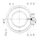
- the pump chamber is delimited by two side parts, an intermediate ring with a spherical inner surface and the spherical surface of the swash plate with a smaller diameter. With its spherical inner surface and the circular ring of the swash plate, the ring forms the dynamic sealing of the delivery chambers from one another. Due to the structural division of the pump chamber walls, only one component is provided with a spherical inner surface for the external sealing of the swash plate outer diameter. The parting line between the components of the pump chamber does not run in the spherical surface, but two parting lines are placed on the side surfaces.
- the spherical inner surface is a sealing surface for sealing the delivery chambers, and the outer diameter of the swash plate is moved over this surface. By shifting the parting line to the side surface, the best possible match of the outer contours is achieved to achieve the tightness.
- This design of the pump chamber with separate side surfaces and ring is made possible by a recess in the ring.
- the swashplate is inserted into the ring in a vertical orientation, placed concentrically and brought into the operational position by pivoting. An intermediate wall is then anchored at the location of the recess and sealed against the ring. The minimum width of the recess is determined from the width of the swash plate.
- the development according to claim 6 teaches, inter alia, the use of an intermediate wall in which elastic sealing elements are provided between the intermediate wall and the side walls for sealing against the side walls.
- This can be a vulcanized layer on the intermediate wall, it is but also independent sealing elements can be used.
- the partition is installed in the ring at the location of the recess after the swash plate is installed. It has a spherical surface with the same radius as the spherical surface carrying the swash plate and sits on it while maintaining a sealing gap.
- the partition is dimensioned so that there is still a space between it and the ring.
- An elastic seal is inserted in this to seal the partition against the ring. This elastic seal exerts a contact pressure on the adapter and creates a gap-free static seal on the side walls.
- the development according to claim 7 forms a double static seal of the pump chamber against the atmosphere. This increases the area of application of the pump for pumping aggressive or toxic media. If the second static seal applied by the pumped medium fails, the first static seal functions as additional protection.
- the development according to claim 8 enables high mobility of the second static seal through the use of an elastic membrane.
- the space enclosed between the first and second static seals can be filled with a liquid. Since liquids are considered incompressible and the volume of the space divided by the membrane remains constant, no pressure difference is built up on the membrane. Rather, the same pressure prevails on both sides of it and the membrane is only stressed by the wobble movement.
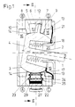
- FIG. 1 shows a swash plate pump, in which a swash plate shaft (1) is moved by a drive (not shown), describing a double-conical surface, about a wobble point (2).
- the wobble point (2) coincides with the center of the spherical surface (3) of the swash plate (4) and the spherical inner surface (5) of a ring (6).
- these surfaces delimit a pump chamber (11) of a first side part (9) on the drive side, which has a central opening, and a second side part (10).
- the swash plate shaft (1) can be connected to the swash plate (4) in different ways, for example welding, screwing or the like.
- the swash plate (4) can be made in one piece to achieve the greatest possible precision. Of course, a construction composed of several parts is also possible.
- the outer edge of the The circular ring (12) of the swash plate (4) is preferably designed with a contour corresponding to the spherical inner surface (5) in order to achieve a dynamic seal.
- the pump chamber (11) is sealed against the interior of the pump by dynamic sealing between the spherical surface (3) and the corresponding spherical surfaces (13, 14) of the side parts (9, 10).
- the swash plate (4) can also be supported at these points. Due to the gap of the dynamic seal on the spherical surfaces (3, 13, 14), the side spaces (15, 16) of the pump are acted upon by the pumped medium.
- the side space (15) acted upon by the pumped medium is closed off by means of a membrane (17).
- the membrane (17) is attached to the spherical surface (3) and on the side part (9) and is statically sealed there.
- the membrane (17) does not have to be designed to accommodate the pressure difference from the atmosphere.
- the pressure difference is in this embodiment of a further sealing element, e.g. in the form of a bellows (18) shown here.
- a space (19) through which there is no flow is located between the bellows (18) and the membrane (17). This can be filled with a control medium. Since the membrane (17) is elastic and deformable, the same hydrostatic pressure is established in the space (19) as in the side space (15) and the membrane (17) is only subjected to deformation.
- the bellows (18) absorbs the pressure difference and follows the wobbling movement of the swash plate (4) with elastic deformation of the folds. It statically seals the space (19) against the atmosphere and against the storage space (20) of the swash plate shaft (1).
- the bellows (18) is attached at one end to the tumbling part and at the other end to a fixed housing part, here for example in the form of a cover (21) with a central opening for the passage of the swash plate shaft (1).
- the bellows (18) secures the swash plate (4) against rotation around the Central axis of the bellows (18).
- this anti-rotation device can also be made in other known ways.
- the cover (21) also seals the membrane (17) and is connected to the side part (9).
- the side part (9) is provided with connections (C, D) through which the side space (15) can be fully included in the flow.
- Connections (A, B) are provided on the side part (10) for the flow through the side space (16).
- the sequence of the flow through the side spaces (15, 16) and the pump chamber (11) can be selected according to the respective operating conditions.
- the side spaces (15, 16) can be flowed through before the pumping medium enters the pump chamber (11) or after the pumping medium exits the pump chamber (11).
- the housing of the swash plate pump is held together by known means.
- a feature of the swash plate pump is the separation of the suction and pressure sides of the pump chamber (11) by an intermediate wall (22) arranged transversely to the pump chamber (11).
- the circular ring (12) of the swash plate (4) has a recess with at least the wall thickness of the intermediate wall (22). Since the wobble movement of the swash plate (4) in the pump chamber (11) is composed of two superimposed rotary movements about the two axes spanning the central axis of the pump chamber (11), the surfaces of the recess facing the partition wall lead to a relative movement the fixed partition (22). The minimum width of the recess depends on the shape of its surface. The surfaces of the recess do not have to have a sealing function with the intermediate wall (22). It is also possible to allow a greater play between the surfaces of the recess and the intermediate wall (22).
- the partition (22) sits with play on the spherical surface (3), is provided with a corresponding sealing surface (23) and is e.g. in the side parts (9, 10) anchored by dowel pins (24).
- An elastic coating (25) of the side flanks of the intermediate wall (22) ensures the static sealing by contacting the side surfaces (7, 8).
- other forms of static sealing are also conceivable.
- the side rooms (15, 16) as well as the room (19) and the storage room (20) can be provided with a monitoring device (not shown here). This enables an early detection of a seal leak.
- the space (19) in particular can be filled with a control medium, the change of which can be monitored with sensors.
- a medium that is compatible with the pumped medium is suitable as the control medium.
- the cleaning process is carried out by introducing a rinsing liquid into the side spaces (15, 16) and into the pump chamber (11). During the cleaning process, the cleaning liquid comes into contact with all surfaces and rooms affected by the medium.
- a rinsing liquid comes into contact with all surfaces and rooms affected by the medium.
- the Conveyor operation of the swash plate pump takes place when the side spaces (15, 16) flow through, a continuous self-cleaning process and limits the dwell time of a particle of the pumped medium in the pump. This enables the conveyance of sensitive, time-critical media.
Landscapes
- Engineering & Computer Science (AREA)
- Mechanical Engineering (AREA)
- General Engineering & Computer Science (AREA)
- Reciprocating Pumps (AREA)
- Lubrication Of Internal Combustion Engines (AREA)
- Details Of Reciprocating Pumps (AREA)
Claims (9)
- Pompe à disque en nutation, dans laquelle, à l'aide d'un axe de disque en nutation (1), un disque en nutation (4), dans une chambre de pompe (11) formée par deux surfaces latérales (7, 8) et, entre elles, des surfaces internes et externes (3, 5) sphériques placées sur des diamètres divers, effectue un mouvement de nutation, dans laquelle le disque en nutation (4) est muni d'une bague circulaire (12) placée sur une surface sphérique (3), dans laquelle une paroi intermédiaire (22) partageant la bague circulaire (12) du disque en nutation (4) et formant l'ouverture d'aspiration et de refoulement est placée dans le boîtier, avec au moins un premier espace latéral (16) placé à une face du disque en nutation à l'opposé d'un entraînement ainsi qu'avec un second espace latéral (15) placé à une face du disque en nutation dirigée vers l'entraînement, ces deux espaces étant, à partir de la chambre de pompe (11), remplis du liquide de refoulement après passage de joints dynamiques, un premier joint élastique statique (18) étant prévu pour fermer l'espace rempli de liquide de refoulement contre l'arbre du disque en nutation (1), caractérisée en ce que des espaces (15, 16) remplis de liquide de refoulement sont reliés à la zone d'aspiration et/ou de refoulement de la pompe et sont traversés par le liquide en continu ou de manière régulée dans le sens du courant de refoulement.
- Pompe à disque en nutation selon la revendication 1 caractérisée en ce que le liquide traverse un espace latéral avant d'entrer dans la chambre de pompe (11) et un autre espace latéral après être sorti de la chambre de pompe (11).
- Pompe à disque en nutation selon la revendication 1 caractérisée en ce que le liquide traverse les espaces latéraux avant d'entrer dans la chambre de pompe (11).
- Pompe à disque en nutation selon la revendication 1 caractérisée en ce que le liquide traverse les espaces latéraux après être sorti de la chambre de pompe (11).
- Pompe à disque en nutation selon la revendication 1 et une des revendications 2 à 4 caractérisée en ce que les surfaces latérales (7, 8) sont accolées à une bague (6) située entre elles à surface interne (5) sphérique et que la bague (6) possède, dans la surface interne (5) entre des ouvertures (27, 28) d'entrée et de sortie situées sur la circonférence, un évidement (26) dont la largeur correspond au moins à la largeur de la bague circulaire (12) du disque en nutation (4).
- Pompe à disque en nutation selon la revendication 5 caractérisée en ce que la paroi intermédiaire (22) présente, sur le côté tourné vers la surface sphérique (3) du disque en nutation (4), une surface sphérique (23) lui correspondant, en ce que la paroi intermédiaire (22) est reliée aux surfaces latérales (7, 8) de la chambre de pompe (11) et étanchéisée statiquement par rapport aux surface latérales (7, 8) et à la bague (6) par des éléments d'étanchéité élastiques (25, 29).
- Pompe à disque en nutation selon l'une ou plusieurs des revendications 1 à 6 caractérisée en ce qu'un second joint élastique (17) est placé en amont d'un premier joint (18) statique élastique, dans laquelle le second espace latéral (15) soumis à la pression du liquide est placé entre le joint dynamique sur les surfaces sphériques (3, 13) et le second joint statique élastique (17).
- Pompe à disque en nutation selon la revendication 7 caractérisée en ce que le second joint statique (17) est une membrane élastique.
- Pompe à disque en nutation selon les revendications 7 et 8 caractérisée en ce que l'espace (19) entre le premier et le second joint statique est rempli d'un liquide de contrôle et relié à un dispositif de surveillance.
Applications Claiming Priority (3)
| Application Number | Priority Date | Filing Date | Title |
|---|---|---|---|
| DE4131628A DE4131628A1 (de) | 1991-09-23 | 1991-09-23 | Taumelscheibenpumpe |
| DE4131628 | 1991-09-23 | ||
| PCT/EP1992/002076 WO1993006371A1 (fr) | 1991-09-23 | 1992-09-08 | Pompe a disque en nutation |
Publications (2)
| Publication Number | Publication Date |
|---|---|
| EP0605471A1 EP0605471A1 (fr) | 1994-07-13 |
| EP0605471B1 true EP0605471B1 (fr) | 1995-07-19 |
Family
ID=6441271
Family Applications (1)
| Application Number | Title | Priority Date | Filing Date |
|---|---|---|---|
| EP92918927A Expired - Lifetime EP0605471B1 (fr) | 1991-09-23 | 1992-09-08 | Pompe a disque en nutation |
Country Status (9)
| Country | Link |
|---|---|
| US (1) | US5454699A (fr) |
| EP (1) | EP0605471B1 (fr) |
| JP (1) | JP2742727B2 (fr) |
| KR (1) | KR100236027B1 (fr) |
| AT (1) | ATE125334T1 (fr) |
| CA (1) | CA2117201C (fr) |
| DE (2) | DE4131628A1 (fr) |
| DK (1) | DK0605471T3 (fr) |
| WO (1) | WO1993006371A1 (fr) |
Families Citing this family (14)
| Publication number | Priority date | Publication date | Assignee | Title |
|---|---|---|---|---|
| CZ155695A3 (en) * | 1992-12-16 | 1996-01-17 | Hofmann Manfred | Machine with whirling piston |
| DE4405945C2 (de) * | 1994-02-24 | 1998-07-09 | Klein Schanzlin & Becker Ag | Taumelscheibenpumpe mit durchströmten Seitenräumen |
| SE510007C2 (sv) * | 1994-11-03 | 1999-03-29 | Tetra Laval Holdings & Finance | Pump med vridbar och fram och åter rörlig kolv |
| US5980225A (en) * | 1996-07-05 | 1999-11-09 | Sundstrand Fluid Handling Corporation | Rotary pump having a drive shaft releasably connected to the rotor |
| KR100419142B1 (ko) * | 1999-03-18 | 2004-02-14 | 김종대 | 자이로 펌프 |
| RU2271475C2 (ru) * | 2004-02-24 | 2006-03-10 | Сергей Сергеевич Кочанов-Сорокин | Роторный насос |
| WO2007084014A1 (fr) * | 2006-01-18 | 2007-07-26 | Swashpump Technologies Limited | Ameliorations de pompes a plateau oscillant |
| SE531601C2 (sv) * | 2007-10-11 | 2009-06-02 | Itt Mfg Enterprises Inc | Pump, krängningsskivpump och sönderdelningsarrangemang i pumpar |
| NZ592364A (en) | 2008-10-23 | 2013-05-31 | Swashpump Technologies Ltd | Integrated swash plate pump and motor for compressible and elastic fluids such as explosive gases |
| NZ582354A (en) | 2009-12-24 | 2010-05-28 | Swashpump Technologies Ltd | Non-rotating nutating plate pump with compound spherical bearing |
| WO2019081967A1 (fr) * | 2017-10-26 | 2019-05-02 | Paul Zehnder | Machine à plateau oscillant avec entraînement |
| WO2019081966A1 (fr) | 2017-10-26 | 2019-05-02 | Paul Zehnder | Pompe à disque en nutation |
| DE202018106140U1 (de) | 2018-10-26 | 2018-11-07 | Paul Zehnder | Taumelscheibenpumpe |
| DE102021114237A1 (de) | 2021-06-01 | 2022-12-01 | Pumpsystems Gmbh | Taumelringpumpe für Lebensmittel |
Family Cites Families (10)
| Publication number | Priority date | Publication date | Assignee | Title |
|---|---|---|---|---|
| GB1143675A (fr) * | 1900-01-01 | |||
| US2329604A (en) * | 1941-07-14 | 1943-09-14 | Aro Equipment Corp | Fluid meter |
| DE1090966B (de) * | 1954-10-29 | 1960-10-13 | Richard T Cornelius | Taumelscheibenpumpe |
| GB861332A (en) * | 1959-03-02 | 1961-02-15 | Richard Thomas Cornelius | Pulsation reducing wabble pump structure |
| DE1277673B (de) * | 1965-11-12 | 1968-09-12 | Reginald Clarence Ford | Pumpe mit Nutationsscheibe |
| DE2617516A1 (de) * | 1976-04-22 | 1977-11-03 | Fritz Reis | Kolbenmaschine fuer stroemende medien |
| FI873787A7 (fi) * | 1987-09-04 | 1989-03-02 | Altukhova, Lilia Vsevolodovna | Foerbaettring roerande membranmaskin. |
| DE3831068A1 (de) * | 1988-09-13 | 1990-03-22 | Sihi Gmbh & Co Kg | Verfahren zur reinigung einer stoffbuchslosen, rotierend arbeitenden foerdereinrichtung fuer fluide |
| DE3905419A1 (de) * | 1989-02-22 | 1990-08-30 | Richter Chemie Technik Gmbh | Verfahren zur verminderung von mit foerderfluessigkeit gefuellten totraeumen in pumpen und pumpe mit vermindertem totraum |
| US5125809A (en) * | 1990-03-27 | 1992-06-30 | Product Research And Development | Wobble plate pump |
-
1991
- 1991-09-23 DE DE4131628A patent/DE4131628A1/de not_active Withdrawn
-
1992
- 1992-09-08 DE DE59202979T patent/DE59202979D1/de not_active Expired - Lifetime
- 1992-09-08 AT AT92918927T patent/ATE125334T1/de not_active IP Right Cessation
- 1992-09-08 JP JP5505738A patent/JP2742727B2/ja not_active Expired - Fee Related
- 1992-09-08 US US08/211,346 patent/US5454699A/en not_active Expired - Lifetime
- 1992-09-08 KR KR1019940700933A patent/KR100236027B1/ko not_active Expired - Fee Related
- 1992-09-08 CA CA002117201A patent/CA2117201C/fr not_active Expired - Fee Related
- 1992-09-08 EP EP92918927A patent/EP0605471B1/fr not_active Expired - Lifetime
- 1992-09-08 DK DK92918927.2T patent/DK0605471T3/da active
- 1992-09-08 WO PCT/EP1992/002076 patent/WO1993006371A1/fr not_active Ceased
Also Published As
| Publication number | Publication date |
|---|---|
| WO1993006371A1 (fr) | 1993-04-01 |
| DE4131628A1 (de) | 1993-03-25 |
| CA2117201A1 (fr) | 1993-04-01 |
| US5454699A (en) | 1995-10-03 |
| KR100236027B1 (ko) | 1999-12-15 |
| EP0605471A1 (fr) | 1994-07-13 |
| DE59202979D1 (de) | 1995-08-24 |
| JP2742727B2 (ja) | 1998-04-22 |
| CA2117201C (fr) | 2002-07-23 |
| DK0605471T3 (da) | 1995-12-04 |
| ATE125334T1 (de) | 1995-08-15 |
| KR940702589A (ko) | 1994-08-20 |
| JPH06506750A (ja) | 1994-07-28 |
Similar Documents
| Publication | Publication Date | Title |
|---|---|---|
| EP0605471B1 (fr) | Pompe a disque en nutation | |
| DE69123898T3 (de) | Drehanlage für flüssige Medien | |
| DE3878073T2 (de) | Fluessigkeitsverdichter. | |
| DE1901748C3 (de) | Hydraulische Rotationsschlauchpumpe | |
| DE2825616C2 (de) | Lager- und Dichtungsanordnung an den Wellen einer Zahnradpumpe | |
| DE102016100957A1 (de) | Verdrängerpumpe | |
| DE102004031350B4 (de) | Zwei-Wege-Drehdurchführung | |
| EP0899223A1 (fr) | Ecluse à roue cellulaire pour le dosage de matières en vrac | |
| EP0617201B1 (fr) | Dispositif de remplissage et de transport de fluides à travers d'une pompe | |
| DE19502173C2 (de) | Schraubenpumpe für drehrichtungsunabhängigen Betrieb | |
| DE69026945T2 (de) | Impulsfreie kolbenpumpe | |
| DE60212165T2 (de) | Flanschzahnradpumpe | |
| WO1995029339A1 (fr) | Pompe a courroie a denture interieure | |
| DE19516578C1 (de) | Innenzahnradpumpe, geeigneet zur sterilen Reinigung im Durchlaufverfahren ohne Demontage | |
| DE102020124825A1 (de) | Motor-Pumpe-Einheit | |
| EP1336780B1 (fr) | Joint secondaire pour dispositif de joint d'étanchéité à bague glissante | |
| DE3320090A1 (de) | Verdraengerpumpe | |
| DE2402283B2 (de) | Hydrostatische pumpe bzw. hydrostatischer motor | |
| DE69002809T2 (de) | Flüssigkeitsverdichter. | |
| EP0430099B1 (fr) | Pompe à pistons radiaux, en particulier pour des installations hydrauliques, ainsi que l'élément de mise sous pression | |
| DE3132285A1 (de) | Pumpeneinheit | |
| DE962498C (de) | Membranpumpe | |
| EP0995906A1 (fr) | Pompe centrifuge double entrainée par un moteur | |
| DE102017011154B3 (de) | Rotierende Verdrängerpumpe zum Fördern von fließfähigen Stoffen, Laufrad für eine solche und Verfahren zum Fördern mit einer solchen Verdrängerpumpe | |
| DE1277673B (de) | Pumpe mit Nutationsscheibe |
Legal Events
| Date | Code | Title | Description |
|---|---|---|---|
| PUAI | Public reference made under article 153(3) epc to a published international application that has entered the european phase |
Free format text: ORIGINAL CODE: 0009012 |
|
| 17P | Request for examination filed |
Effective date: 19940309 |
|
| AK | Designated contracting states |
Kind code of ref document: A1 Designated state(s): AT CH DE DK FR GB IT LI |
|
| 17Q | First examination report despatched |
Effective date: 19941219 |
|
| GRAA | (expected) grant |
Free format text: ORIGINAL CODE: 0009210 |
|
| AK | Designated contracting states |
Kind code of ref document: B1 Designated state(s): AT CH DE DK FR GB IT LI |
|
| REF | Corresponds to: |
Ref document number: 125334 Country of ref document: AT Date of ref document: 19950815 Kind code of ref document: T |
|
| REF | Corresponds to: |
Ref document number: 59202979 Country of ref document: DE Date of ref document: 19950824 |
|
| ITF | It: translation for a ep patent filed | ||
| ET | Fr: translation filed | ||
| GBT | Gb: translation of ep patent filed (gb section 77(6)(a)/1977) |
Effective date: 19951002 |
|
| REG | Reference to a national code |
Ref country code: DK Ref legal event code: T3 |
|
| PLBE | No opposition filed within time limit |
Free format text: ORIGINAL CODE: 0009261 |
|
| 26N | No opposition filed | ||
| REG | Reference to a national code |
Ref country code: GB Ref legal event code: IF02 |
|
| PGFP | Annual fee paid to national office [announced via postgrant information from national office to epo] |
Ref country code: DK Payment date: 20090923 Year of fee payment: 18 |
|
| PGFP | Annual fee paid to national office [announced via postgrant information from national office to epo] |
Ref country code: GB Payment date: 20090925 Year of fee payment: 18 Ref country code: CH Payment date: 20090923 Year of fee payment: 18 Ref country code: AT Payment date: 20090928 Year of fee payment: 18 |
|
| PGFP | Annual fee paid to national office [announced via postgrant information from national office to epo] |
Ref country code: DE Payment date: 20090908 Year of fee payment: 18 |
|
| PGFP | Annual fee paid to national office [announced via postgrant information from national office to epo] |
Ref country code: IT Payment date: 20090921 Year of fee payment: 18 |
|
| REG | Reference to a national code |
Ref country code: CH Ref legal event code: PL |
|
| GBPC | Gb: european patent ceased through non-payment of renewal fee |
Effective date: 20100908 |
|
| REG | Reference to a national code |
Ref country code: DK Ref legal event code: EBP |
|
| PG25 | Lapsed in a contracting state [announced via postgrant information from national office to epo] |
Ref country code: IT Free format text: LAPSE BECAUSE OF NON-PAYMENT OF DUE FEES Effective date: 20100908 |
|
| REG | Reference to a national code |
Ref country code: FR Ref legal event code: ST Effective date: 20110531 |
|
| REG | Reference to a national code |
Ref country code: DE Ref legal event code: R119 Ref document number: 59202979 Country of ref document: DE Effective date: 20110401 |
|
| PG25 | Lapsed in a contracting state [announced via postgrant information from national office to epo] |
Ref country code: LI Free format text: LAPSE BECAUSE OF NON-PAYMENT OF DUE FEES Effective date: 20100930 Ref country code: FR Free format text: LAPSE BECAUSE OF NON-PAYMENT OF DUE FEES Effective date: 20100930 Ref country code: CH Free format text: LAPSE BECAUSE OF NON-PAYMENT OF DUE FEES Effective date: 20100930 Ref country code: DE Free format text: LAPSE BECAUSE OF NON-PAYMENT OF DUE FEES Effective date: 20110401 |
|
| PG25 | Lapsed in a contracting state [announced via postgrant information from national office to epo] |
Ref country code: AT Free format text: LAPSE BECAUSE OF NON-PAYMENT OF DUE FEES Effective date: 20100908 Ref country code: GB Free format text: LAPSE BECAUSE OF NON-PAYMENT OF DUE FEES Effective date: 20100908 |
|
| PGFP | Annual fee paid to national office [announced via postgrant information from national office to epo] |
Ref country code: FR Payment date: 20091006 Year of fee payment: 18 |
|
| PG25 | Lapsed in a contracting state [announced via postgrant information from national office to epo] |
Ref country code: DK Free format text: LAPSE BECAUSE OF NON-PAYMENT OF DUE FEES Effective date: 20100930 |