EP0605548B1 - Presse - Google Patents
Presse Download PDFInfo
- Publication number
- EP0605548B1 EP0605548B1 EP92920098A EP92920098A EP0605548B1 EP 0605548 B1 EP0605548 B1 EP 0605548B1 EP 92920098 A EP92920098 A EP 92920098A EP 92920098 A EP92920098 A EP 92920098A EP 0605548 B1 EP0605548 B1 EP 0605548B1
- Authority
- EP
- European Patent Office
- Prior art keywords
- pivot point
- linkage
- press
- pivot
- pivoted
- Prior art date
- Legal status (The legal status is an assumption and is not a legal conclusion. Google has not performed a legal analysis and makes no representation as to the accuracy of the status listed.)
- Expired - Lifetime
Links
- 238000013459 approach Methods 0.000 claims description 15
- 238000005452 bending Methods 0.000 abstract 2
- 238000009957 hemming Methods 0.000 description 32
- 238000012423 maintenance Methods 0.000 description 1
Images


Classifications
-
- B—PERFORMING OPERATIONS; TRANSPORTING
- B21—MECHANICAL METAL-WORKING WITHOUT ESSENTIALLY REMOVING MATERIAL; PUNCHING METAL
- B21D—WORKING OR PROCESSING OF SHEET METAL OR METAL TUBES, RODS OR PROFILES WITHOUT ESSENTIALLY REMOVING MATERIAL; PUNCHING METAL
- B21D39/00—Application of procedures in order to connect objects or parts, e.g. coating with sheet metal otherwise than by plating; Tube expanders
- B21D39/02—Application of procedures in order to connect objects or parts, e.g. coating with sheet metal otherwise than by plating; Tube expanders of sheet metal by folding, e.g. connecting edges of a sheet to form a cylinder
- B21D39/021—Application of procedures in order to connect objects or parts, e.g. coating with sheet metal otherwise than by plating; Tube expanders of sheet metal by folding, e.g. connecting edges of a sheet to form a cylinder for panels, e.g. vehicle doors
-
- Y—GENERAL TAGGING OF NEW TECHNOLOGICAL DEVELOPMENTS; GENERAL TAGGING OF CROSS-SECTIONAL TECHNOLOGIES SPANNING OVER SEVERAL SECTIONS OF THE IPC; TECHNICAL SUBJECTS COVERED BY FORMER USPC CROSS-REFERENCE ART COLLECTIONS [XRACs] AND DIGESTS
- Y10—TECHNICAL SUBJECTS COVERED BY FORMER USPC
- Y10T—TECHNICAL SUBJECTS COVERED BY FORMER US CLASSIFICATION
- Y10T29/00—Metal working
- Y10T29/53—Means to assemble or disassemble
- Y10T29/53709—Overedge assembling means
- Y10T29/53787—Binding or covering
- Y10T29/53791—Edge binding
Definitions
- This invention relates to a press having a press tool and a drive mechanism, and in particular, but not exclusively, is concerned with what is known as "hemming" panels, such as automotive body panels.
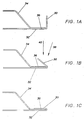
- FIGS 1A to 1C of the accompanying drawings illustrate hemming of inner and outer panels.
- the marginal edge 30 of an outer panel 32 (part of which is shown) is initially upturned at about 90°, as shown in Figure 1A, and is fixed in a jig.
- An inner panel 34 is then placed over the outer panel 32 and is fixed in the jig, such that the outer edge 36 of the inner panel 34 sits close to the bend between the outer panel 32 and its marginal edge 30.
- the marginal edge 30 is bent over at approximately 45°, as shown in Figure 1B.
- the marginal edge 30 of the outer panel 32 is pressed down flat under great pressure against the outer edge 36 of the inner panel 34, as shown in Figure 1C.
- the movement of the final hem tool is important. If the panel were to have straight edges, then movement of the tool in the direction marked 38 in Figure 1B might be acceptable. However, many body panels have curved edges and in these cases it is desirable to use a curved final press tool to hem a large extent of a curve. However, if the tool moved in a direction 38 in the plane of the paper of Figure 1B at one location along the edge of the panel, at other locations the movement would be inclined relative to the plane of the paper of Figure 1B, and there would be undesirable movement between the tool and the marginal edge 30, which would produce an unsatisfactory result. For a satisfactory result, it is desirable that the final hem tool moves vertically, as shown by arrow 40 in Figure 1B.
- a pre-hemming tool is illustrated at 5, and a final hemming tool is illustrated at 6.
- the pre-hemming tool 5 is mounted for movement by a parallelogram mechanism having axes 10, 11, 12, 13 and is driven by a hydraulic piston and cylinder arrangement 22 through a lever 16 pivoted about a fixed pivot 18 and through a linkage 28.
- the final press tool 6 is mounted on a parallelogram arrangement having axes 17, 18, 19, 20, and the lever 16 forms one of the linkages of this parallelogram arrangement.
- the line connecting the axes 11, 13 of the first parallelogram arrangement is generally at 60° to the horizontal, and therefore the movement of the pre-hemming tool 5 at this stage is approximately at 30° to the horizontal.
- the line connecting the axes 18, 20 of the second parallelogram arrangement is generally horizontal, and therefore the movement of the final hemming tool 6 at this stage is generally vertical.
- a press comprises: a lever pivoted about a first fixed pivot point; first and second linkages pivoted about second and third pivot points, respectively, on the lever, the second pivot point being intermediate the first and third pivot points; a third linkage pivoted about a fourth pivot point with respect to the second linkage and pivoted about a fifth pivot point; a mechanism for moving the fourth pivot point; a fourth linkage pivoted about the fifth pivot and pivoted with respect to the first linkage about a sixth pivot point; and a press tool mounted on the first linkage and facing in a direction generally parallel to the direction from the sixth pivot point to the second pivot point.
- the press is arranged so that, as the press approaches a final pressing position of the press tool: the fifth pivot point is fixed; the press tool moves in a direction generally parallel to the direction from the sixth to second pivot points; and the third, fourth and fifth pivot points approach alignment.
- the force applied by the mechanism for moving the fourth pivot point results in a greatly amplified force pushing the third pivot point away from the fifth pivot point.
- This latter force is then further amplified by the lever (because the second pivot point is between the first and third pivot points) and transmitted by the first linkage to the press tool.
- the alignment of the third, fourth and fifth pivot points is generally parallel to the direction between the second and sixth pivot points.
- the lever and the first, second, third and fourth linkages approach a parallelogram configuration to produce a desirable final movement of the press tool.
- the mechanism for moving the fourth pivot point comprises a crank rotatable about a seventh pivot point, and a fifth linkage pivoted about an eighth pivot point with respect to the crank and pivoted about the fourth pivot point, and, as the press approaches the final pressing position, the fourth, seventh and eighth pivot points approach alignment.
- a drive torque applied to the crank can produce a high force on the fourth pivot point.
- the press of the present invention preferably further comprises: a sixth linkage pivoted about a ninth fixed pivot point and pivoted about the fifth pivot point; and an abutment (preferably adjustable) which limits the movement of the sixth linkage so that as the press approaches the final pressing position the fifth pivot point becomes fixed.
- the fifth pivot point can move before and after the final pressing stage so that the final press tool can be moved away to facilitate loading and unloading of the press with panels.
- a first cam element may be formed on the second linkage adjacent the third pivot point, and a second cam element may be provided beneath the third pivot point.
- the first cam element engages the second cam element to lift the third pivot point and thereby lift the lever and the second pivot point.
- the abutment is adjustable, it provides a simple and convenient way of adjusting the length of travel of the press tool.
- the press of the present invention may be provided with a pre-pressing tool.
- the press may further conveniently comprise a seventh linkage pivoted about the first fixed pivot point; an eighth linkage pivoted about a tenth fixed pivot point; a ninth linkage pivoted about eleventh and twelfth pivot points with respect to the seventh and eighth linkages, respectively, so that the seventh, eighth and ninth linkages are arranged generally as a parallelogram; and a mechanism for moving the twelfth pivot point; the pre-pressing tool being mounted on the ninth linkage and arranged to engage a workpiece prior to engagement by the main press tool.
- the arrangement may be such that a line from the first to the tenth pivot points rises at about 30° to the horizontal.
- the mechanism for moving the twelfth pivot point may comprise an arm projecting from the eighth linkage; a tenth linkage pivoted to the arm at a thirteenth pivot point; and a second crank moving with the first crank and pivoted with respect to the tenth linkage at a fourteenth pivot point.
- the piston and cylinder arrangements 21 of the known hemming press required large and expensive hydraulic control packs, and in view of space restrictions, these have in the past been mounted above the press, thus further hindering access. Also, maintenance of hydraulic systems can be expensive and messy.
- the press of the present invention enables an electric motor to be used for driving the first (and second) crank. Electric motors are clean and less expensive to maintain, and the controller therefor is less expensive and small in size.
- the press comprises a base 40 with a pair of side walls 42, only one of which is shown, and an upper wall 44.
- An electric motor 46 having a worm gearbox 48 is mounted on one of the side walls 42.
- a number of fixed pivots are provided between the side walls 42 mounted on one or both of the side walls, namely fixed pivots FP1, FP9 and FP10.
- the gear box 48 has an output shaft with a fixed axis FP7.
- a lever V1 extends generally to the right from the first fixed pivot FP1 and provides thereon second and third pivots P2, P3.
- a first linkage K1 is connected at the second pivot P2 and extends generally upwardly.
- a second linkage K2 is connected at the third pivot P3 and extends to a fourth pivot P4.
- a third linkage K3 is connected at the fourth pivot P4 and extends to a fifth pivot P5.
- a fourth linkage K4 is connected at the fifth pivot P5 and is also connected at a sixth pivot P6 to the first linkage K1.
- a sixth linkage K6 is connected at the fifth pivot P5 and is also pivoted at the ninth fixed pivot FP9.
- a crank C1 is mounted on the gearbox shaft FP7.
- a fifth linkage K5 is connected at an eighth pivot P8 to the crank C1 and is also connected to the fourth pivot P4.
- a final press tool 50 is mounted on the first linkage K1.
- An abutment 52 depends from the upper wall 44 and is screw threaded into the upper wall 44 so that the position of the abutment 52 can be adjusted.
- the lower end of the second linkage K2 is formed as a first cam element M1 for engagement with a second roller cam element M2 mounted for rotation about a fixed cam pivot PM beneath the third pivot P3.
- a seventh linkage K7 is pivoted about the first fixed pivot FP1, and an eighth linkage K8 is pivoted about the tenth fixed pivot FP10.
- a ninth linkage K9 connects the seventh and eighth linkages K7, K8 at eleventh and twelfth pivot points P11, P12, respectively, so that the seventh to ninth linkages K7, K8, K9 form a parallelogram arrangement.
- a pre-hemming tool 54 is mounted on the ninth linkage K9.
- the eighth linkage K8 has a projecting arm K8' which is connected at a thirteenth pivot P13 to a tenth linkage K10, which is pivoted at a fourteenth pivot P14 to a second crank C2 which is also fixed on the gearbox shaft FP7.
- Figure 5 shows the start/finish position of the press, and it can be seen that the final hemming tool 50 is withdrawn well to the side of the hem area 28 to increase the access region for the panels.
- the gearbox shaft FP7 is rotated anti-clockwise.
- the second crank C2 rotates anti-clockwise, and the second crank C2 and tenth linkage K10 become more aligned.
- the eighth linkage K8 pivots around the tenth fixed pivot FP10 causing the parallelogram mounting of the pre-hemming tool 54 to rotate anti-clockwise.
- a stage is reached, as shown in Figure 6, in which the second crank C2 and tenth linkage K10 are aligned, the seventh and eighth linkages K7, K8 are generally at 60° to the horizontal, and the pre-hemming tool 54 is in its outermost position and has engaged the marginal edge of the outer panel and bent it through approximately 45°.
- the second and third linkages K2, K3 become more aligned.
- the first cam element M1 rides over the second cam element M2, and the third pivot P3 begins to drop slightly.
- the first linkage K1 becomes vertical and the fourth and sixth linkages K4, K6 become aligned and the sixth linkage K6 bears against the abutment 52, as shown in Figure 7, at about the same time as the final hemming tool 50 touches the marginal edge of the outer panel.
- the final position of the final hemming tool 50 is controlled by the adjustable abutment 52. If the abutment is adjusted downwardly, then the final tool 50 will have a greater downward travel, and vice versa .
- the machine may be returned to the position shown in Figure 5 by reversing the electric motor 46.
- the machine could be redesigned so that continued anti-clockwise rotation of the first and second cranks C1, C2 causes the machine to return to its start position.
Landscapes
- Engineering & Computer Science (AREA)
- Mechanical Engineering (AREA)
- Press Drives And Press Lines (AREA)
- Mounting, Exchange, And Manufacturing Of Dies (AREA)
- Shaping Metal By Deep-Drawing, Or The Like (AREA)
- Bending Of Plates, Rods, And Pipes (AREA)
Claims (10)
- Presse mit:
einem Hebel (V1), der um einen ersten festen Schwenkpunkt (FP1) schwenkbar ist,
ersten und zweiten Verbindungsgliedern (K1, K2), die um zweite bzw. dritte Schwenkpunkte (P2, P3) auf dem Hebel schwenkbar sind, wobei der zweite Schwenkpunkt (P2) zwischen dem ersten und dem dritten Schwenkpunkt (FP1, P3) liegt,
einem dritten Verbindungsglied (K3), welches um einen vierten Schwenkpunkt bezüglich des zweiten Verbindungsgliedes schwenkbar und auch um einen fünften Schwenkpunkt (P5) schwenkbar ist,
einem Mechanismus (K5, P8, C1), um den vierten Schwenkpunkt zu bewegen,
einem vierten Verbindungsglied (K4), welches um den fünften Schwenkpunkt und bezüglich des ersten Verbindungsgliedes um einen sechsten Schwenkpunkt (P6) schwenkbar ist, und
einem Presswerkzeug (50), welches an dem ersten Verbindungsglied montiert ist und einer Richtung im wesentlichen parallel zur Richtung vom sechsten Schwenkpunkt zum zweiten Schwenkpunkt zugewandt ist,
wobei, wenn die Presse eine endgültige Pressposition des Presswerkzeuges einnimmt:
der fünfte Schwenkpunkt fixiert ist,
das Presswerkzeug sich in einer Richtung im wesentlichen parallel zu der Richtung vom sechsten zum zweiten Schwenkpunkt bewegt und
die dritten, vierten und fünften Schwenkpunkte sich einer miteinander ausgerichteten Position annähern. - Presse nach Anspruch 1, wobei, wenn die Presse sich der endgültigen Pressposition annähert, die Ausrichtung der dritten, vierten und fünften Schwenkpunkte etwa parallel zur Richtung zwischen den zweiten und sechsten Schwenkpunkten ist.
- Presse nach Anspruch 1 oder 2, wobei:
der Mechanismus zum Bewegen des vierten Schwenkpunktes eine erste Kurbel (C1) aufweist, die um einen siebten Punkt (FP7) drehbar ist, und ein fünftes Verbindungsglied (K5) aufweist, welches um einen achten Schwenkpunkt (P8) bezüglich der Kurbel schwenkbar ist und auch um den vierten Schwenkpunkt schwenkbar ist, und wobei,
wenn die Presse sich der endgültigen Pressposition annähert, die vierten, siebten und achten Schwenkpunkte sich einer Ausrichtung annähern. - Presse nach einem der vorstehenden Ansprüche, welche weiterhin aufweist:
ein sechstes Verbindungsglied (6), welches um einen neunten festen Schwenkpunkt (FP9) und um den fünften Schwenkpunkt schwenkbar ist, und
einen Anschlag (52), der die Bewegung des sechsten Verbindungsgliedes begrenzt, so daß dann, wenn die Presse sich der endgültigen Pressposition annähert, der fünfte Schwenkpunkt fixiert wird. - Presse nach Anspruch 4, wobei der Anschlag einstellbar ist, um die feste Position des fünften Schwenkpunktes zu verändern.
- Presse nach Anspruch 4 oder 5, wobei:
in der endgültigen Pressposition der sechste Schwenkpunkt im wesentlichen vertikal oberhalb des zweiten Schwenkpunktes liegt,
ein erstes Nockenelement (M1) an dem zweiten Verbindungsglied neben dem dritten Schwenkpunkt ausgebildet ist,
ein zweites Nockenelement (M2) unter dem dritten Schwenkpunkt vorgesehen ist, und
wenn die Presse von der endgültigen Pressposition wegbewegt wird, das erste Nockenelement mit dem zweiten Nockenelement in Eingriff tritt, um den dritten Schwenkpunkt anzuheben und damit den Hebel und den zweiten Schwenkpunkt anzuheben. - Presse nach einem der vorstehenden Ansprüche, welche weiterhin aufweist:
ein siebtes Verbindungsglied (K7), welches um den ersten festen Schwenkpunkt schwenkbar ist,
ein achtes Verbindungsglied (K8), welches um einen zehnten festen Schwenkpunkt (FP10) schwenkbar ist,
ein neuntes Verbindungsglied (K9), welches um elfte und zwölfte Schwenkpunkte (P11, P12) bezüglich der siebten bzw. achten Verbindungsglieder schwenkbar ist, so daß die siebten, achten und neunten Verbindungsglieder im wesentlichen als ein Parallelogramm angeordnet sind,
einen Mechanismus (K8, P13, K10, P14, C2), um den zwölften Schwenkpunkt zu bewegen, und
ein Vorpresswerkzeug (54), welches an dem neunten Verbindungsglied montiert ist und welches so angeordnet ist, daß es mit einem Werkstück (28) vor dem Eingriff durch das vorerwähnte Hauptpresswerkzeug in Eingriff tritt. - Presse nach Anspruch 7, wobei eine Linie von dem ersten zum zehnten Schwenkpunkt unter etwa 30° relativ zu einer Horizontalen ansteigt.
- Presse nach Anspruch 3 und Anspruch 7 oder 8, wobei der Mechanismus zum Bewegen des zwölften Schwenkpunktes aufweist:
einen Arm (K8'), welcher von dem achten Verbindungsglied hervorsteht,
ein zehntes Verbindungsglied (K10), welches an einem dreizehnten Schwenkpunkt (P13) mit dem Arm schwenkbar verbunden ist, und
eine zweite Kurbel (C2), welche sich mit der ersten Kurbel bewegt und bezüglich des zehnten Verbindungsgliedes an einem vierzehnten Schwenkpunkt (P14) schwenk- bzw. drehbar ist. - Presse nach einem der Ansprüche 3 oder 9, welche weiterhin einen elektrischen Motor (46) für den Antrieb der ersten und zweiten Kurbeln aufweist.
Applications Claiming Priority (3)
| Application Number | Priority Date | Filing Date | Title |
|---|---|---|---|
| GB9120627 | 1991-09-27 | ||
| GB9120627A GB2259879B (en) | 1991-09-27 | 1991-09-27 | Press |
| PCT/GB1992/001713 WO1993005902A1 (en) | 1991-09-27 | 1992-09-17 | Press |
Publications (2)
| Publication Number | Publication Date |
|---|---|
| EP0605548A1 EP0605548A1 (de) | 1994-07-13 |
| EP0605548B1 true EP0605548B1 (de) | 1995-11-15 |
Family
ID=10702113
Family Applications (1)
| Application Number | Title | Priority Date | Filing Date |
|---|---|---|---|
| EP92920098A Expired - Lifetime EP0605548B1 (de) | 1991-09-27 | 1992-09-17 | Presse |
Country Status (8)
| Country | Link |
|---|---|
| US (1) | US5495742A (de) |
| EP (1) | EP0605548B1 (de) |
| AT (1) | ATE130225T1 (de) |
| CA (1) | CA2110895C (de) |
| DE (1) | DE69206153T2 (de) |
| ES (1) | ES2079890T3 (de) |
| GB (1) | GB2259879B (de) |
| WO (1) | WO1993005902A1 (de) |
Families Citing this family (21)
| Publication number | Priority date | Publication date | Assignee | Title |
|---|---|---|---|---|
| US5457981A (en) * | 1992-10-14 | 1995-10-17 | Western Atlas, Inc. | Hemming press |
| CA2089813A1 (en) * | 1992-10-14 | 1994-04-15 | Gerald A. Brown | Hemming press |
| SE502596C2 (sv) * | 1994-03-23 | 1995-11-20 | Volvo Ab | Anordning vid en bockningsenhet |
| DE4440815A1 (de) * | 1994-11-15 | 1996-05-23 | Bayerische Motoren Werke Ag | Verfahren zum Herstellen einer Falzverbindung |
| IT1278350B1 (it) * | 1995-02-02 | 1997-11-20 | Comau Spa | Dispositivo per la graffatura di elementi di lamiera metallica stampata. |
| FR2734184B1 (fr) * | 1995-05-18 | 1997-08-01 | Peugeot | Unite de presertissage et de sertissage du bord d'une tole |
| FR2735049B1 (fr) * | 1995-06-09 | 1997-08-22 | Peugeot | Unite de presertissage et de sertissage du bord d'une tole |
| FR2742082B1 (fr) * | 1995-12-11 | 1998-02-06 | Bema | Dispositif de sertissage de panneaux en tole |
| FR2744381B1 (fr) | 1996-02-02 | 1998-04-24 | Peugeot | Unite de presertissage et de sertissage du bord d'une tole |
| FR2774010B1 (fr) * | 1998-01-28 | 2000-04-14 | Peugeot | Dispositif de sertissage |
| US5930880A (en) * | 1998-02-06 | 1999-08-03 | Tesco Engineering, Inc. | Intensification method and apparatus for hemming machine |
| FR2776545B1 (fr) * | 1998-03-30 | 2000-06-16 | Peugeot | Dispositif combine de presertissage et de sertissage |
| FR2776546B1 (fr) * | 1998-03-30 | 2000-06-16 | Peugeot | Unite de presertissage et de sertissage du bord d'une tole |
| GB9810366D0 (en) * | 1998-05-14 | 1998-07-15 | D V Automation Ltd | Press |
| US6314783B1 (en) | 2000-05-05 | 2001-11-13 | William Patrick | Electromechanical hemming apparatus and method |
| US20020157441A1 (en) * | 2001-02-27 | 2002-10-31 | William Patrick | Die hemming assembly and method |
| US6467324B2 (en) | 2001-02-27 | 2002-10-22 | William Patrick | Die hemming assembly and method |
| ITTO20030349A1 (it) * | 2003-05-13 | 2004-11-14 | P M C Tecnologie Srl | Unita' per la graffiatura di lamiere. |
| US20060179914A1 (en) * | 2005-02-11 | 2006-08-17 | Tesco Engineering Inc. | Pre-hemming tool for robotic hemming |
| US9631710B1 (en) * | 2013-11-14 | 2017-04-25 | Gary A. Slinger | Multiple purpose tool assembly |
| ES1096031Y (es) * | 2013-11-27 | 2014-03-11 | Ingemat S L (100 0%) | Unidad de engatillado |
Family Cites Families (9)
| Publication number | Priority date | Publication date | Assignee | Title |
|---|---|---|---|---|
| GB958671A (en) * | 1960-08-31 | 1964-05-21 | British Federal Welder | Clinching apparatus |
| US4706489A (en) * | 1985-12-05 | 1987-11-17 | Utica Enterprises, Incorporated | Single station hemming tooling |
| SE461194B (sv) * | 1988-03-21 | 1990-01-22 | Volvo Ab | Bockningsanordning |
| SE460770B (sv) * | 1988-03-21 | 1989-11-20 | Volvo Ab | Bockningsanordning |
| SE461021B (sv) * | 1988-03-21 | 1989-12-18 | Volvo Ab | Bockningsanordning |
| SE460769B (sv) * | 1988-03-21 | 1989-11-20 | Volvo Ab | Bockningsanordning |
| US5083355A (en) * | 1990-04-30 | 1992-01-28 | Utica Enterprises, Inc. | Hemming apparatus |
| US5005398A (en) * | 1990-06-01 | 1991-04-09 | Craftmation, Inc. | Hemming machine |
| US5272905A (en) * | 1992-09-14 | 1993-12-28 | General Motors Corporation | Exterior mandrel for multiaxis bender |
-
1991
- 1991-09-27 GB GB9120627A patent/GB2259879B/en not_active Expired - Fee Related
-
1992
- 1992-09-17 AT AT92920098T patent/ATE130225T1/de not_active IP Right Cessation
- 1992-09-17 ES ES92920098T patent/ES2079890T3/es not_active Expired - Lifetime
- 1992-09-17 CA CA002110895A patent/CA2110895C/en not_active Expired - Lifetime
- 1992-09-17 WO PCT/GB1992/001713 patent/WO1993005902A1/en not_active Ceased
- 1992-09-17 US US08/162,041 patent/US5495742A/en not_active Expired - Lifetime
- 1992-09-17 EP EP92920098A patent/EP0605548B1/de not_active Expired - Lifetime
- 1992-09-17 DE DE69206153T patent/DE69206153T2/de not_active Expired - Fee Related
Also Published As
| Publication number | Publication date |
|---|---|
| EP0605548A1 (de) | 1994-07-13 |
| ES2079890T3 (es) | 1996-01-16 |
| ATE130225T1 (de) | 1995-12-15 |
| CA2110895C (en) | 1999-12-21 |
| GB2259879B (en) | 1994-03-23 |
| US5495742A (en) | 1996-03-05 |
| GB9120627D0 (en) | 1991-11-06 |
| WO1993005902A1 (en) | 1993-04-01 |
| GB2259879A (en) | 1993-03-31 |
| DE69206153D1 (de) | 1995-12-21 |
| DE69206153T2 (de) | 1996-06-20 |
| CA2110895A1 (en) | 1993-04-01 |
Similar Documents
| Publication | Publication Date | Title |
|---|---|---|
| EP0605548B1 (de) | Presse | |
| JP2675347B2 (ja) | ヘミング成形装置 | |
| EP0665070B1 (de) | Falzpresse | |
| US5454261A (en) | Hemming machine and method of operation | |
| US6474125B1 (en) | Hemming machine with dual ball screw drive | |
| CA1337254C (en) | Transfer device in a transfer press or similar metal-forming machine | |
| EP0407443B1 (de) | Faltvorrichtung | |
| JP2004517733A (ja) | 電気的縁取りプレス | |
| KR20000011868A (ko) | 금속 시트를 펀칭 가공 및 굽힘 가공하는 기계 | |
| KR100604201B1 (ko) | 서보모터를 이용한 클린칭 타입의 헤밍장치 | |
| JPS6312697B2 (de) | ||
| WO2018055180A1 (de) | Werkzeug und werkzeugmaschine sowie verfahren zur bearbeitung von plattenförmigen werkstücken | |
| EP0427886A1 (de) | Form für ein negatives Eckstück | |
| CN114346041A (zh) | 一种板材加工用冲压装置及冲压方法 | |
| US7487659B2 (en) | Machine for working sheet metal parts, in particular a flanging machine, and a system for driving the machine | |
| CN116727501B (zh) | 一种钣金加工折弯装置 | |
| CN116037737B (zh) | 一种汽车白车身四门两盖压边装置 | |
| JP3452165B2 (ja) | 板金ワークのヘミング加工方法 | |
| JP7365920B2 (ja) | 曲げ機械用の追従装置 | |
| WO2001012355A1 (de) | Vorrichtung zur betätigung eines stössels in einer hub- oder spannvorrichtung, insbesondere zum falzen von blechen im automobilbau | |
| CN113618363A (zh) | 一种可对压合方向进行调节的精密伺服电子压力机 | |
| EP0958870B1 (de) | Presse | |
| CN218051306U (zh) | 攻牙折弯一体机 | |
| JPH03180215A (ja) | 折曲げ加工機 | |
| EP1132157B1 (de) | Biege- und Falzverfahren sowie Biege- und Falzvorrichtung |
Legal Events
| Date | Code | Title | Description |
|---|---|---|---|
| PUAI | Public reference made under article 153(3) epc to a published international application that has entered the european phase |
Free format text: ORIGINAL CODE: 0009012 |
|
| 17P | Request for examination filed |
Effective date: 19931001 |
|
| AK | Designated contracting states |
Kind code of ref document: A1 Designated state(s): AT BE DE ES FR GB IT NL SE |
|
| 17Q | First examination report despatched |
Effective date: 19941229 |
|
| GRAA | (expected) grant |
Free format text: ORIGINAL CODE: 0009210 |
|
| AK | Designated contracting states |
Kind code of ref document: B1 Designated state(s): AT BE DE ES FR GB IT NL SE |
|
| PG25 | Lapsed in a contracting state [announced via postgrant information from national office to epo] |
Ref country code: NL Free format text: LAPSE BECAUSE OF FAILURE TO SUBMIT A TRANSLATION OF THE DESCRIPTION OR TO PAY THE FEE WITHIN THE PRESCRIBED TIME-LIMIT Effective date: 19951115 Ref country code: AT Effective date: 19951115 |
|
| REF | Corresponds to: |
Ref document number: 130225 Country of ref document: AT Date of ref document: 19951215 Kind code of ref document: T |
|
| REF | Corresponds to: |
Ref document number: 69206153 Country of ref document: DE Date of ref document: 19951221 |
|
| ET | Fr: translation filed | ||
| REG | Reference to a national code |
Ref country code: ES Ref legal event code: FG2A Ref document number: 2079890 Country of ref document: ES Kind code of ref document: T3 |
|
| ITF | It: translation for a ep patent filed | ||
| PG25 | Lapsed in a contracting state [announced via postgrant information from national office to epo] |
Ref country code: SE Effective date: 19960215 |
|
| NLV1 | Nl: lapsed or annulled due to failure to fulfill the requirements of art. 29p and 29m of the patents act | ||
| PLBE | No opposition filed within time limit |
Free format text: ORIGINAL CODE: 0009261 |
|
| STAA | Information on the status of an ep patent application or granted ep patent |
Free format text: STATUS: NO OPPOSITION FILED WITHIN TIME LIMIT |
|
| 26N | No opposition filed | ||
| REG | Reference to a national code |
Ref country code: GB Ref legal event code: IF02 |
|
| PGFP | Annual fee paid to national office [announced via postgrant information from national office to epo] |
Ref country code: BE Payment date: 20040922 Year of fee payment: 13 |
|
| PG25 | Lapsed in a contracting state [announced via postgrant information from national office to epo] |
Ref country code: BE Free format text: LAPSE BECAUSE OF NON-PAYMENT OF DUE FEES Effective date: 20050930 |
|
| PGFP | Annual fee paid to national office [announced via postgrant information from national office to epo] |
Ref country code: ES Payment date: 20070702 Year of fee payment: 16 |
|
| BERE | Be: lapsed |
Owner name: *D V AUTOMATION LTD Effective date: 20050930 |
|
| PGFP | Annual fee paid to national office [announced via postgrant information from national office to epo] |
Ref country code: GB Payment date: 20070920 Year of fee payment: 16 |
|
| PGFP | Annual fee paid to national office [announced via postgrant information from national office to epo] |
Ref country code: IT Payment date: 20070921 Year of fee payment: 16 Ref country code: DE Payment date: 20071123 Year of fee payment: 16 |
|
| PGFP | Annual fee paid to national office [announced via postgrant information from national office to epo] |
Ref country code: FR Payment date: 20070611 Year of fee payment: 16 |
|
| GBPC | Gb: european patent ceased through non-payment of renewal fee |
Effective date: 20080917 |
|
| REG | Reference to a national code |
Ref country code: FR Ref legal event code: ST Effective date: 20090529 |
|
| PG25 | Lapsed in a contracting state [announced via postgrant information from national office to epo] |
Ref country code: IT Free format text: LAPSE BECAUSE OF NON-PAYMENT OF DUE FEES Effective date: 20080917 Ref country code: DE Free format text: LAPSE BECAUSE OF NON-PAYMENT OF DUE FEES Effective date: 20090401 |
|
| PG25 | Lapsed in a contracting state [announced via postgrant information from national office to epo] |
Ref country code: FR Free format text: LAPSE BECAUSE OF NON-PAYMENT OF DUE FEES Effective date: 20080930 |
|
| REG | Reference to a national code |
Ref country code: ES Ref legal event code: FD2A Effective date: 20080918 |
|
| PG25 | Lapsed in a contracting state [announced via postgrant information from national office to epo] |
Ref country code: GB Free format text: LAPSE BECAUSE OF NON-PAYMENT OF DUE FEES Effective date: 20080917 |
|
| PG25 | Lapsed in a contracting state [announced via postgrant information from national office to epo] |
Ref country code: ES Free format text: LAPSE BECAUSE OF NON-PAYMENT OF DUE FEES Effective date: 20080918 |