EP0605795A2 - Verfahren zur Handhabung von Kopffeldern in Ringnetzwerken - Google Patents
Verfahren zur Handhabung von Kopffeldern in Ringnetzwerken Download PDFInfo
- Publication number
- EP0605795A2 EP0605795A2 EP93119424A EP93119424A EP0605795A2 EP 0605795 A2 EP0605795 A2 EP 0605795A2 EP 93119424 A EP93119424 A EP 93119424A EP 93119424 A EP93119424 A EP 93119424A EP 0605795 A2 EP0605795 A2 EP 0605795A2
- Authority
- EP
- European Patent Office
- Prior art keywords
- ring
- network
- transport overhead
- command
- signal
- Prior art date
- Legal status (The legal status is an assumption and is not a legal conclusion. Google has not performed a legal analysis and makes no representation as to the accuracy of the status listed.)
- Granted
Links
- 238000000034 method Methods 0.000 title claims abstract description 77
- 230000004044 response Effects 0.000 claims abstract description 32
- 238000001514 detection method Methods 0.000 abstract description 6
- 238000004891 communication Methods 0.000 description 32
- 230000008569 process Effects 0.000 description 19
- 230000008901 benefit Effects 0.000 description 11
- 230000006870 function Effects 0.000 description 11
- 230000005540 biological transmission Effects 0.000 description 10
- 230000001186 cumulative effect Effects 0.000 description 10
- 230000002457 bidirectional effect Effects 0.000 description 9
- 230000000694 effects Effects 0.000 description 9
- 238000010586 diagram Methods 0.000 description 8
- 239000000835 fiber Substances 0.000 description 8
- 230000003287 optical effect Effects 0.000 description 5
- 230000009286 beneficial effect Effects 0.000 description 4
- 230000001360 synchronised effect Effects 0.000 description 4
- 230000008859 change Effects 0.000 description 3
- 230000009471 action Effects 0.000 description 2
- 230000004888 barrier function Effects 0.000 description 2
- 238000005516 engineering process Methods 0.000 description 2
- 238000012423 maintenance Methods 0.000 description 2
- 230000007246 mechanism Effects 0.000 description 2
- 238000012986 modification Methods 0.000 description 2
- 230000004048 modification Effects 0.000 description 2
- 238000012544 monitoring process Methods 0.000 description 2
- 230000003534 oscillatory effect Effects 0.000 description 2
- 238000012545 processing Methods 0.000 description 2
- 238000009825 accumulation Methods 0.000 description 1
- 238000012937 correction Methods 0.000 description 1
- 230000001419 dependent effect Effects 0.000 description 1
- 238000009432 framing Methods 0.000 description 1
- 230000006872 improvement Effects 0.000 description 1
- 230000010355 oscillation Effects 0.000 description 1
- 230000001105 regulatory effect Effects 0.000 description 1
- 238000010561 standard procedure Methods 0.000 description 1
- 238000013024 troubleshooting Methods 0.000 description 1
Images



Classifications
-
- H—ELECTRICITY
- H04—ELECTRIC COMMUNICATION TECHNIQUE
- H04J—MULTIPLEX COMMUNICATION
- H04J3/00—Time-division multiplex systems
- H04J3/02—Details
- H04J3/14—Monitoring arrangements
-
- H—ELECTRICITY
- H04—ELECTRIC COMMUNICATION TECHNIQUE
- H04J—MULTIPLEX COMMUNICATION
- H04J3/00—Time-division multiplex systems
- H04J3/02—Details
- H04J3/08—Intermediate station arrangements, e.g. for branching, for tapping-off
- H04J3/085—Intermediate station arrangements, e.g. for branching, for tapping-off for ring networks, e.g. SDH/SONET rings, self-healing rings, meashed SDH/SONET networks
-
- H—ELECTRICITY
- H04—ELECTRIC COMMUNICATION TECHNIQUE
- H04J—MULTIPLEX COMMUNICATION
- H04J3/00—Time-division multiplex systems
- H04J3/02—Details
- H04J3/12—Arrangements providing for calling or supervisory signals
-
- H—ELECTRICITY
- H04—ELECTRIC COMMUNICATION TECHNIQUE
- H04L—TRANSMISSION OF DIGITAL INFORMATION, e.g. TELEGRAPHIC COMMUNICATION
- H04L12/00—Data switching networks
- H04L12/28—Data switching networks characterised by path configuration, e.g. LAN [Local Area Networks] or WAN [Wide Area Networks]
- H04L12/42—Loop networks
- H04L12/437—Ring fault isolation or reconfiguration
-
- H—ELECTRICITY
- H04—ELECTRIC COMMUNICATION TECHNIQUE
- H04J—MULTIPLEX COMMUNICATION
- H04J2203/00—Aspects of optical multiplex systems other than those covered by H04J14/05 and H04J14/07
- H04J2203/0001—Provisions for broadband connections in integrated services digital network using frames of the Optical Transport Network [OTN] or using synchronous transfer mode [STM], e.g. SONET, SDH
- H04J2203/0057—Operations, administration and maintenance [OAM]
- H04J2203/006—Fault tolerance and recovery
Definitions
- This invention is in the field of telecommunications, and is more particularly directed to a method of managing ring network overhead transport during network failure conditions and subsequent restoration.
- SONET synchronous optical network
- SONET has for the first time defined a standard optical interface which allows so-called “mid-span” meets, that is, interfaces between equipment produced by different manufacturers.
- This standard has particular application to the present invention in that it describes common generic criteria for optical ring networks.
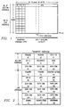
- FIG. 1 illustrates an STS-1 frame.
- the STS-1 frame consists of 90 columns and 9 rows of 8-bit bytes (shown as "B"), for a total of 810 bytes (6480 bits).
- B 8-bit bytes
- the STS-1 frame has a length of 125 microseconds (i.e., 8,000 frames per second).
- the bytes of the STS-1 frame are transmitted in a row-by-row fashion from right to left. Further, for each byte, the most significant bit is transmitted first.
- multiple STS-1s may be synchronously multiplexed into higher rate STS-N signals.
- STS-N signals are converted to optical OC-N signals for transport through fiber optic media.
- the transport overhead contains overhead bytes of both section overhead and line overhead. Under current standards, twenty-seven bytes are assigned for transport overhead, with nine bytes of section overhead and eighteen bytes of line overhead.
- the section overhead deals with the transportation of an STS-N frame across the physical layer or physical media of the ring. Functions of this section overhead include framing, scrambling, section error monitoring, and communicating section level overhead.
- the line layer provides synchronization and multiplexing functions for the path layer (the path layer deals with the transport of network services between SONET terminal multiplexing equipment). The line overhead associated with these functions includes overhead for maintenance and protection purposes.
- SONET functionally specifies particular bytes in the section and line transport overhead. These bytes are also referred to in the art as defining "channels".
- Figure 2 generally illustrates these bytes with the letter designations given by SONET. While the position of each byte is specified by SONET, the functionality of various bits or even complete bytes for particular designations remain unspecified for certain applications. For example, and as set forth in greater detail below, the K1 line overhead byte has no current specification for unidirectional rings. As another example, bits 3-5 (with bit 1 being the most significant bit) of the K2 line overhead byte are likewise unspecified by SONET for unidirectional rings.
- Synchronous Optical Network (SONET) Transport Systems Common Generic Criteria , Technical Reference TR-NWT-000253, Issue 2, December 1991, published by Bellcore, and incorporated herein by reference.
- the remaining 87 columns of the STS-1 frame are the STS-1 envelope capacity.
- STS-1 envelope capacity Within the STS-1 envelope capacity is placed a synchronous payload envelope (SPE).
- SPE synchronous payload envelope
- One column of the SPE contains nine bytes, designated as STS path overhead. This column may be located at any column within the STS-1 envelope capacity. The remaining 774 bytes are available for payload.
- the STS-1 SPE may begin anywhere in the STS envelope capacity. Typically, it begins in one frame and ends in the next. The STS-1 SPE may, however, be wholly contained in one frame.
- STS path overhead is associated with each payload and is used to communicate functions from the point where service is mapped into the STS SPE to where it is delivered.
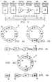
- Figure 3 illustrates a simplified block diagram to delineate various definitions of the transmission network that interconnect various SONET NEs. Specifically, the SONET line, section and path are shown. Figure 3 further illustrates path terminating equipment 10 and 12, line terminating equipment 14 and 16, and section "terminating" equipment 18 and 20. As known in the art, an NE is said to be terminating if it is specified that during normal operations, the device may alter the corresponding information associated with it. For example, path terminating equipment 10 and 12 are defined to be equipment which are permitted to alter the path portion of the SONET frame (see Figure 1). Line terminating equipment 14 and 16 are specified so that they are permitted to alter the line information of the SONET frame. Finally, section terminating equipment 18 and 20 are specified so that they may alter the section information of the SONET frame.
- An example of STS-1 SPE path terminating equipment is an add/drop multiplexer.
- An add/drop multiplexer is also line terminating.
- an example of section terminating equipment is a repeater. Note that a device specified as capable of terminating one category of information necessarily can terminate subset categories. Thus, path terminating equipment 10 and 12 may also terminate line and section information. Further, line terminating equipment 14 and 16 may also terminate section information. Note also that the termination specifications apply only during normal operations. For example, while a repeater is section terminating, during a failure it may alter other information such as the K1 and K2 line overhead bytes.
- improper restoration of the transport overhead channel in the ring network may cause an oscillatory action to occur along the network.
- Such oscillation may occur when the ring becomes "closed” as to transport, that is, having no barrier to prevent the transport overhead from continuously encircling the ring.
- This unimpeded travel allows an NE to add transport overhead to the ring, and subsequently receive back the same overhead, in addition to any accumulated overhead added by other NEs.
- This cumulative feedback around the ring may provide undesirable results. For example, for audio transport overhead, such undesirable effects may include high level audio feedback which is received by any NE monitoring the ring.
- FIG. 4a illustrates a block diagram of a prior art telecommunications ring network 22.
- ring network 22 is a unidirectional path protection switched (PPS) telecommunications ring network.
- PPS path protection switched
- a unidirectional ring as known in the art, is one in which traffic generally travels in one medium and direction between elements along the ring, while concurrently flowing in a redundant manner in an opposite direction in another medium. Note also that transport overhead, as opposed to traffic, is communicated bidirectionally between NEs on a unidirectional ring.
- Ring network 22 includes a first ring 24 and a second ring 26. As illustrated, traffic flow around first ring 24 is clockwise, while traffic flow around second ring 26 is counterclockwise.
- both rings 24 and 26 traverse through various NEs positioned along the ring.
- four NEs are provided and are designated with corresponding numerals (e.g., NE0, NE1, NE2 and NE3).
- one of rings 24 or 26 is predetermined as the primary communication medium for traffic flow around the ring.
- first ring 24 as this predetermined ring.
- communication between any of the NEs along the ring is, under normal operating conditions, in a clockwise fashion.
- a redundant signal is provided along second ring 26 in a counterclockwise fashion.
- this redundant signal permits the network element to select between the primary and redundant signals according to the transport performance information received by the corresponding NE.
- Figure 4b illustrates network ring 22 of Figure 4a, with the additional indication that NE0 has implemented an "artificial transport overhead break" 28.
- a transport overhead break is known in the art for preventing ring network 22 from becoming a closed ring. Without overhead break 28, transport overhead would be permitted to continue uninterrupted around the entirety of ring 22 and, hence, could cause the undesirable accumulation and feedback effects discussed above.
- the effect of the overhead break 28 is to prevent the transport overhead from fully encircling the ring and, consequently, also to prevent undesirable cumulative feedback effects.
- Figure 4c illustrates a block diagram of the effective communication path for the transport overhead caused by the artificial transport overhead break 28 illustrated in Figure 4b.
- the direct line of transport overhead communication between NE0 and NE3 is effectively severed by artificial transport overhead break 28.
- any transport overhead communication between these two NEs must be communicated through NE1 and NE2. Nonetheless, transport overhead communication is still permitted between each NE of the ring, without the possibility of cumulative feedback.
- Figure 4d illustrates ring network 22 of Figure 4a, wherein both rings 24 and 26 have been severed (illustrated by an "X" on rings 24 and 26). The severance may occur due to a physical disturbance of rings 24 and 26, or like situation.
- the NEs along the rings include circuitry for detecting the loss of an incoming signal. When a signal loss occurs, a detecting NE inserts an "actual" transport overhead break on the side of the NE which would receive the signal if it existed. An actual overhead break is to be contrasted with an artificial overhead break. The former occurs upon detection of an actual fault with the ring or one of its components.
- the NE imposing the break may evaluate the transport overhead. It does not, however, transmit the overhead to the using application, or pass it through to the remainder of the network.
- ring network 22 is shown with an actual failure between NE2 and NE3.
- NE2 and NE3 detect a loss of signal along rings 26 and 24, respectively.
- both NE2 and NE3 force an actual transport overhead break 30 and 32, respectively, on their corresponding sides detecting the failure.
- Overhead breaks 30 and 32 function in the same manner as artificial overhead break 28 associated with NE0.
- breaks 30 and 32 preclude transport overhead information received by NE2 from transmitting along ring 24 toward NE3.
- overhead break 32 prevents overhead information received by NE3 from transmitting along ring 26 toward NE2.
- Figure 4e illustrates the effective communication path for the transport overhead of network ring 22.
- overhead breaks 28, 30 and 32 act in combination to segment or isolate NE3 from the remainder of the NEs of ring 22.
- NE3 cannot communicate transport overhead with the remainder of the ring network.
- the ring network is simply left in its segmented form, with no restoration of transport overhead to the segmented NE or NEs.
- One key object of the present invention is to maintain a constant communication path between all NEs despite a fault along one of the rings (for example, as shown in Figure 4c).
- LTS-21130 One known solution for attempting to restore transport overhead is implemented in the LTS-21130 ring network, formerly owned and sold by Rockwell and currently owned by Alcatel.
- the LTS-21130 is dependent on a strict hardware implementation.
- a "home node” initially imposes an artificial transport overhead break.
- an NE along the ring when detecting a loss of signal, inserts a transport overhead break in the direction of the loss of signal.
- the detecting NE Upon correction of the break, the detecting NE immediately removes its overhead break.
- the detecting node transmits an indication bit and the newly received signal toward the home node.
- the home node upon receiving the forwarded information, reinserts its overhead break.
- the ring Prior to receiving this new information, however, the ring is a closed ring, that is, no overhead break exists on the ring and, therefore, cumulative overhead feedback may occur. Indeed, specific dedicated hardware is included in the home node so that it can quickly reinsert its overhead break before the effects of cumulative overhead feedback become overwhelming.
- the present invention provides a deterministic (i.e., predictable and uniform in result) method in which the reinsertion of an overhead break is ensured to occur prior to the release of the break elsewhere in the ring.
- the ring is never fully closed to overhead, thereby preventing cumulative feedback from occurring.
- the present invention is preferably embodied in software, rather than dedicated hardware.
- One embodiment of the present invention provides a method of restoring transport overhead along a ring network having a plurality of network elements communicating a signal on the ring network.
- This method includes designating a first of the plurality of network elements as a master network element and inserting a first transport overhead break on the ring network by the master network element.
- the method further includes detecting a failure of the signal by a second network element and inserting a second transport overhead break on the ring network by the second network element in response to the detection of a failure.
- the method includes removing the second transport overhead break under the direction of said master network element.
- Another embodiment of the present invention also includes a method of restoring transport overhead along a ring network having a plurality of network elements communicating a signal on the ring network.
- This method also includes the steps of designating a first of the plurality of network elements as a master network element and detecting a failure of the signal by a second network element.
- the method includes the step of transmitting a count to the master network element by the second network element in response to the step of detecting a failure.
- the count is incremented each time it passes through a network element other than the first and second network elements. Finally, the count is received by the master network element.
- the present invention includes detecting a failure of the signal by one of said plurality of network elements followed by initially restoring traffic along the ring network via software communication between the plurality of network elements. Thereafter, transport overhead is subsequently restored along the ring network via software control between the plurality of network elements.
- FIGUREs 5a through 11b of the drawings like numerals being used for like and corresponding parts of the various drawings.
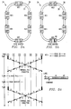
- FIG. 5a is an electrical diagram, in block form, of a telecommunication ring network 34 in which the preferred embodiments of the invention may be used.
- Ring network 34 in the preferred embodiment, is a unidirectional ring including a first ring 36 and a second ring 38.
- ring network 34 includes six NEs, but this in no manner should be construed as limiting the present invention. Indeed, as described in greater detail below, the present invention provides a method whereby the number of NEs along network ring 34 is extremely flexible.
- the six NEs around network ring 34 are arbitrarily designated, in clockwise fashion, NE0, NE4, NE2, NE3, NE6 and NE5.
- each NE includes two transport overhead break indicators (shown as blank rectangles) connected in-line for both rings 36 and 38. As illustrated in greater detail below, a corresponding overhead break indicator is darkened to illustrate the instance where an NE inserts an overhead break in place. As stated in connection with Figures 4d-e above, the overhead break prevents transport overhead communication from the direction of the break.
- Figure 5b illustrates ring network 34 during its normal operation.
- NE0 is designated a ring master.
- the master designation distinguishes the particular NE from all other NEs as more readily apparent below. Any NE within network ring 34 may be designated ring master and, therefore, its application to NE0 is arbitrary.
- the master NE is a path terminating NE. Further, the designation of master is provided in software and preferably stored in non-volatile memory which also includes various other network information.
- the master NE forces an artificial transport overhead break 40 during normal operation of ring network 34.
- this artificial break prevents cumulative feedback of transport overhead during normal operating conditions.
- transport overhead communication cannot directly occur between NE0 and NE5; rather, such communication must pass through the intermediate NEs between the two (i.e., NE4, NE2, NE3 and NE6).
- traffic information is undisturbed by artificial overhead break 40 and passes along first ring 36 or second ring 38 in accordance with standard unidirectional ring protocol.
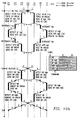
- Figure 5c illustrates a timing message chart of transport overhead along first and second rings 36 and 38 in Figure 5b. Each individual NE is shown across the top of the diagram. The flow from left to right illustrates the clockwise travel of transport overhead along ring 36. Similarly, the flow from right to left illustrates the counterclockwise travel of transport overhead along ring 38. The vertical axis of Figure 5c illustrates time from an initial operating point, t0, toward various subsequent events discussed below.
- the present invention uses a novel system including commands to maintain and restore the transport overhead channels in network ring 34. A numeric label above the direction arrow between each sequential NE around ring 34 identifies which of the particular commands is being transmitted. The label and corresponding command are shown in the legend at the right of the timing message chart. For example, with reference to Figure 5c, the label of "0" illustrates a no request command (i.e., NR) indicating that the network is in a normal idle condition.
- NR no request command
- the legend in Figure 5c also includes an indication of the K1 and K2 transport overhead line bytes (see also, Figure 2). As described in greater detail below, these bytes are used in the preferred embodiment to transmit a count and command signal, respectively.
- the K1 transport line overhead byte is used to communicate a numeric count for implementing this scheme.
- current ring network elements typically include the necessary processing capability for decoding the K1 channel and, hence, the present invention may be implemented with no additional hardware necessary for such a function.
- K2 byte bits of the K2 byte are used to encode the particular commands of the present invention. This channel was selected as preferable because its bits 2-4 are undefined for a unidirectional ring, and those bits are adequate to indicate the various commands described below. Because only bits 2-4 of the K2 byte are used, the remainder of those bits are irrelevant for purposes of the present invention. Thus, these bits are shown as "z” in the legend (and Table 1) accompanying the timing message chart of Figure 5c as well as the other timing message charts discussed below. Note also, as is the case for K1, current ring networks already include the necessary processing capability for decoding the K2 channel as well. In the preferred embodiment, three commands are encoded by the K2 byte. These commands are shown in Table 1, below. Table 1 K2 byte Command Abbreviation z000zzzz No Request NR z011zzzz Signal Failure SF z101zzzz Wait to Restore WTR The particular functions of each command and their use are described in greater detail below.
- the Figure illustrates that at time, t0, NE0 transmits a no request command to NE4 along ring 36. Concurrently, NE0 transmits a no request command to NE5 along ring 38. During normal idle conditions, each receiving NE (i.e., NE4 on ring 36 and NE5 on ring 38) transfers the command onward along its corresponding ring.
- Figure 5c also illustrates that at a time, t1, a failure occurs along the ring. Specific examples of responding to a ring failure in accordance with the present invention are shown in connection with Figures 6a-11b. Figure 5c also shows a time, t2, at which the ring network is restored. Restoration occurs when the failure along the ring has been cured and transport overhead communications are restored to normal operating conditions. These normal conditions commence at a time, t3, and, therefore, operation continues in the same manner as illustrated from time, t0.
- Figures 6a-1 and 6a-2 illustrate one aspect of the preferred method and system of the present invention.
- Figures 6a-1 and 6a-2 illustrate a flow chart
- Figures 5a and 6b-6g illustrate block diagrams
- Figure 6h illustrates a timing message chart, of the various steps of the inventive method and system.
- a start step 42 is shown at the commencement of the inventive method.
- a conditional step 44 determines whether ring 34 is idle (as shown in Figure 5a). If so, control returns to conditional step 44 until the ring is no longer idle. Once the ring is no longer idle, control passes to an operational step 46.
- an NE along ring network 32 detects a loss of signal.
- NE6 detects a fault (indicated as an "X") in the transport overhead communications along ring 36.
- the NE detecting the fault is hereinafter referred to as a "fault detecting NE”.
- the fault detecting NE inserts a transport overhead break on the side of the ring failure.
- This step is shown as a darkened rectangle in Figure 6b on the side of NE6 detecting the fault.
- This overhead break is maintained for a predetermined period of time which, in the preferred embodiment is ten seconds.
- This predetermined time period acts as an interim guarantee that the fault detecting NE will not remove its transport overhead break until it is directed to do so by the master NE. For example, if the faulty signal were restored and no time period were imposed, the fault detecting NE would detect the restored signal and immediately remove its transport overhead break. If this occurred, the ring would be closed and, hence, cumulative feedback could occur.
- the present invention permits the fault detecting NE to remove its break only under the direction of the master NE.
- the predetermined time period is set large enough to force the fault detecting NE to maintain its break while the master NE gains control over the restoration process.
- an alternative, such as a latching function could be used as an alternative.
- the fault detecting NE transmits a signal failure command in the direction opposite from the fault and along the same ring on which the fault is detected.
- NE6 transmits a signal failure (SF) command toward NE5 along first ring 36.
- SF signal failure
- Step 52 determines whether the NE receiving the signal fault command is the master NE. If not, operational step 54 passes the signal fault command onward toward the next NE and away from the fault within ring 36. If, on the other hand, the NE receiving the failure signal is the master NE, the master NE responds as shown in operational step 56.
- step 56 the master NE transmits a wait to restore command back in the direction from which it received the signal fault command.
- Figure 6c illustrates the ring master NE0 transmitting a wait to restore (WTR) command along second ring 38 in the direction in which it received the signal failure command.
- the process continues to operational step 58 wherein the ring master (i.e., NE0) removes its artificial transport overhead break as illustrated in Figure 6d.
- ring 34 includes only a single transport overhead break, that is, the overhead break imposed by the fault detecting NE (i.e., NE6).
- the implementation of a single overhead break within the ring permits overhead communication between each of the ring NEs and, therefore, does not isolate individual NEs from overhead communication.
- an NE along ring 38 receives the WTR command transmitted by the ring master.
- a conditional step 62 determines whether the specific NE which received the WTR command is the fault detecting NE. If it is not, an operational step 64 transmits the WTR command on the same ring to the next NE and in the opposite direction from which it was received.
- Figure 6e illustrates an example of the combination of steps 62 and 64 wherein NE5 receives the WTR command from the ring master. Since NE5 is not the fault detecting NE (rather, NE6 is the fault detecting NE), NE5 responds by forwarding the WTR command onward to ring 38.
- operational step 66 causes the NE to maintain its actual transport overhead break beyond the predetermined period discussed above in connection with operational step 48.
- the fault detecting NE maintains its transport overhead break until it receives a command from the master NE authorizing or directing it to remove its transport overhead break.
- ring network 34 is situated such that transport overhead communication is still possible between each NE along ring 34.
- the transport overhead communication may be used to assist in troubleshooting or identifying the particular type of ring fault which has occurred.
- Ring 34 remains in this state until the master NE authorizes a change and the change is acted upon.
- Operational step 68 of Figure 6a-1 indicates the recognition by the fault detecting NE that the fault along the ring has been corrected. Such detection occurs when the NE receives a new command when it previously was receiving no signal. The time elapsed between steps 66 and 68 is necessarily determined by the time it takes to correct whatever fault occurred along the ring.
- Conditional step 70 determines whether the restoration of the ring signal has occurred before the expiration of the predetermined time period (i.e, ten seconds). If so, control returns to conditional block 68. This potential circular operation between steps 68 and 70 prevents the fault detecting NE from, in effect, toggling back and forth between an overhead break situation and a non-overhead break situation. In addition, as described above, the predetermined time period attempts to ensure that at least one overhead break is always inserted in the ring.
- step 72 the NE receiving the newly restored command acts in response to what the restored signal is directing. For example, if the new command is a no request command, the NE forwards a no request command along the repaired ring in the direction opposite from which the newly received command was received.
- Figure 6f illustrates this occurrence for the current example. Specifically, NE6 detects the restoration of a command along ring 36 (note "X" has been removed indicating failure has been corrected). Because the predetermined time period has elapsed, NE6 forwards a no request (NR) command along ring 36 in the opposite direction from which it was received.
- NR no request
- the newly corrected command is a no request command and, hence, it is passed onward in the opposite direction from which it is received.
- Other commands could be received and acted upon as well. For example, if multiple failures occurred along the same ring, and were corrected at different times, an NE receiving a newly restored command could receive a signal failure command from a second NE prior to the receiving NE. In any instance, the receiving NE takes whatever action is necessary, and then transmits the responsive command onward in the direction opposite from which the original command was received.
- the no request command from the fault detecting NE passes toward the ring master NE, but is received by any intermediate NEs between the fault detecting NE and the ring master NE.
- Conditional step 74 determines whether a specific NE receiving the newly responsive command is the master NE or is simply an intermediate NE. If the receiving NE is not the master, the process passes to operational step 75 wherein the newly restored command is acted on, and forwarded to the next NE. In the current example, therefore, and as shown in Figure 6f, the no request command is forwarded by NE5 to the master NE.
- Operational step 76 ( Figure 6a-2) takes place once the newly restored command reaches the master NE.
- the master NE detects that it is no longer receiving a signal failure command.
- the master NE reinserts its artificial transport overhead break.
- the master NE sends a no request command back along the same ring in the direction from which it just received the new non-signal failure command.
- the ring master NE has reinserted its overhead break and transmitted a no request (NR) command back along ring 38 toward the fault detecting NE (i.e., NE6). Note also that two overhead breaks are currently in place (the second overhead break being maintained by NE6).
- any intermediate NE between the master NE and the fault detecting NE determines whether it is the fault detecting NE. If it is not, operational step 82 acts to forward the no request command onward in the opposite direction from which it was received and, hence, in the direction of the fault detecting NE. Thus, eventually the fault detecting NE receives the no request command in operational step 84. In step 84, the fault detecting NE determines that it is no longer receiving a wait to restore command. In response, and as shown in operational step 86, the fault detecting NE removes its actual transport overhead break. Moreover, it transmits onward the no request command in the opposite direction from which it was received. Thus, at this instance, the pictorial representation of ring 22 shown in Figure 5b is once again re-established. Consequently, the ring transport overhead is fully restored for normal operations and the process returns to start step 42.
- the process and steps discussed above exemplify the preferred method for detecting a signal failure along a ring and restoring some or all transport overhead in an organized and deterministic fashion.
- a novel incrementing and decrementing method is used to effect certain previously described functions.
- the fault detecting NE transmits a signal failure command.
- the fault detecting NE transmits along with this signal failure command a count signal equal to one.
- each intermediate NE increments the accompanying count signal.
- the master NE will receive a count of two along with the signal failure command. This count indicates that the fault detecting NE is two NEs away from the master NE in the direction from which the signal failure command was received.
- the preferred method of the present invention also uses a novel decrementing scheme as well. Specifically, with reference to steps 56 and 60-64 of Figure 6a-1, when the master NE transmits the WTR command, it also transmits an accompanying count equal to the count it previously received with the signal failure command. Further, as any intermediate NE receives the WTR command (as shown in step 60), the intermediate NE decrements the count and forwards it, along with WTR command, onward along the ring (see step 64).
- This decrementing method provides a mechanism for conditional step 62 to determine, for a given NE, whether the NE receiving the WTR is a fault detecting NE.
- an NE determines that it is the fault detecting NE if the count is one.
- the NE determines that it is the fault detecting NE if the count is one.
- ring master NE0 originally sends out a count of two along with a WTR command along second ring 38.
- NE5 receives the WTR command and count of two as an intermediate NE.
- NE5 decrements the count to one and transmits it, along with the WTR command, onto ring 38 in the direction of NE6.
- NE6 receives the WTR command and the count of one.
- NE6 determines from the count of one that it is the fault detecting NE and, hence, the intended recipient of the WTR command. Accordingly, it may respond in the fashion described above in connection with operational step 66 and its subsequent steps.
- each NE along the ring does not require a specific address or knowledge of the ring map for purposes of accomplishing the transport overhead restoration process. Further, no specific hardware or software need be directed or expended in this regard. Moreover, if the ring is reconfigured, such as by the physical addition or removal of other intermediate NEs, no changes or additional addressing schemes or the like are necessary to effect the overhead restoration process. Further, and as set forth in connection with Figure 5c, above, in the preferred embodiment, the K1 byte is used to provide for the count increment/decrement.
- SONET network rings already have appropriate mechanisms for decoding the K1 byte and, thus, no additional circuitry is necessary for implementing the count method of the present invention.
- the K1 byte provides eight bits which are therefore capable of reaching 255 different NEs along a network ring.
- both the incrementing and decrementing scheme provide great flexibility over various size networks wherein the size of the network is subject to change.
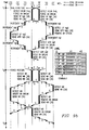
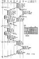
- Figure 6h illustrates the ring timing message chart for the pictorial example shown in Figures 6b-6g, above, and described in connection with the flow chart of Figures 6a-1 and 6a-2.
- a brief discussion follows in connection with Figure 6h for purposes of familiarizing the reader with the illustration of a ring timing message chart between the time of ring failure and the completion of ring restoration.
- ring operation Prior to time t1, ring operation is normal and, hence, is illustrated as shown in Figure 5c.
- NE6 detects a failure as shown in Figure 6b along ring 36.
- NE6 inserts an actual overhead ("OH") break in the direction of NE3.
- NE6 transmits a signal failure command along ring 36 toward NE5.
- the command from NE6 to NE5 is illustrated with the label "1".
- the command is SF N#1.
- the "N#” designation is included for purposes of readability. The number following this designation is the decimal value of the binary count provided by the K1 byte.
- the command is "SF N#1", thereby indicating a signal failure command (i.e., "SF") with a K1 byte count equal to one (i.e., "N#1”).
- label "2" indicates a signal failure command (i.e., "SF”) with a K1 byte count equal to two (i.e., "N#2”). Note also that a count is unnecessary for a no request command. Thus, for this command, no "N#” designation is provided and the K1 byte equals a binary zero.
- Ring 38 is undisturbed by the failure and, therefore, a no request command is transmitted by NE6 toward NE3 along ring 38. Moreover, continuing from NE3 toward NE2 and NE4, it may be appreciated that the no request command continues along ring 38.
- the signal fail command is received by NE5 and its count is incremented as discussed above.
- NE5 send a command bearing the label of "2" to NE0.
- NE0 the master NE, receives the signal failure command.
- the master NE transmits a wait to restore command with the corresponding count of two.
- this new command is transmitted to NE5 with the label "3".
- Label "3" corresponds to a WTR command with a count equal to two.
- Figure 6h illustrates a command sent from NE5 to NE6 having the label "4". From the legend of Figure 6h, the label "4" corresponds to a WTR command having a count of one.
- NE6 recognizes the combination of the WTR signal and the count of one as an indication that it is the intended ultimate recipient of the WTR command. Consequently, NE6 continues to hold its overhead break beyond the predetermined period and transmits a no request command onward along ring 38. Note that the no request command continues to propagate around ring 38 until it reaches NE0. NE0 responds to this no request command by transmitting a no request command back in the direction from which it received the no request command, that is, back toward NE4 and along ring 36. Note also that the process from t1 continues to repeat itself. Thus, as long as ring 36 is faulty, the last issued no request command from NE0 to NE4 along ring 36 does not reach NE6. NE6, therefore, transmits a signal failure command and the process re-commences until the fault on ring 36 is corrected.
- NE6 detects a restoration of signal from ring 36.
- the no request command i.e., label "0”
- NE6 responds to the newly received command as appropriate.
- the response is simply to pass the command onward.
- NE6 passes onward the label "0" command along ring 36 to NE5.
- NE6 also receives a label "4" (i.e., wait to restore) command along ring 38.
- NE6 recognizes the wait to restore signal and continues to maintain its overhead break.
- NE6 transmits a label "0" (i.e., no request) command along ring 38 to NE3.
- the label "0" command transmitted by NE6 along ring 36 is passed by NE5 to the master, NE0.
- the master NE detects the lack of a signal failure command (i.e., the no request command) and responds by inserting its artificial transport overhead break.
- NE0 transmits a no request command onto ring 38 toward the fault detecting NE which is maintaining its break (i.e., NE6).
- This no request command passes through NE5 and is received and detected by NE6.
- NE6 "opens” or removes its actual transport overhead break and transmits a no request command onto ring 38 toward NE3.
- ring 36 and ring 38 are fully operational and the entire ring system is returned to a normal operating condition.
- Figure 7a illustrates a pictorial representation of a second example of the method and system of the present invention. Specifically, Figure 7a illustrates ring network 34 wherein a fault has occurred along ring 36 between NE6 and NE5. Thus, the example illustrates a single break in ring system 34 which is detected by an NE immediately adjacent the ring master NE. With reference to the timing message chart of Figure 7b, the ring fault occurs between NE6 and NE5 along ring 36 at time t1. NE5 detects the ring failure (i.e., signal loss) and forces an actual transport overhead break between itself and NE6 along ring 36.
- ring failure i.e., signal loss
- NE5 transmits a signal failure command in the direction opposite from where the detected failure occurred and, hence, in the direction of ring master NE0 along ring 36.
- Figure 7b illustrates the transmission from NE5 to NE0 of a label "1" signal which, as shown, corresponds to a signal failure command having a count equal to one.
- NE5 transmits a legend "0" command (i.e., no request) to NE6 along ring 38.
- NE0 receives the signal failure command from NE5 without it having passed through any intermediate NEs. As a result, the count provided along with the signal failure command is equal to one. NE0 detects the signal failure command and associated count and responds by sending a wait to restore command along with the count of one back toward NE5. Thus, a label "2" command is provided along ring 38 toward NE5. Moreover, NE0 continues to transmit a no request command along ring 36 toward NE4.
- NE5 receives the wait to restore signal and the associated count of one from NE0. From this signal, NE5 determines that it is the intended ultimate recipient of the wait to restore command and, hence, maintains its actual transport overhead break in place, pending direction from the master NE that the break may be removed. Moreover, NE5 transmits a no request command toward NE6 along ring 36 and continuously transmits a signal failure command to NE0 along ring 36. These conditions continue until the fault between NE5 and NE6 along ring 36 is restored.
- NE5 receives a label "0" command from ring 36. This command is passed onward by NE5 to NE0.
- NE5 continues to transmit a label "0" command around ring 38.
- NE0 receives the label "0" command from NE5.
- NE0 as the master NE, detects the no request command and, hence, the lack of a signal failure command from the previously faulty ring 36. In response, NE0 reinserts its artificial transport overhead break.
- NE0 transmits a no request command back toward the same direction from which it received the no request command indicating restoration of communication along ring 36.
- a no request command is transmitted along ring 38 back toward NE5.
- NE5 receives the no request command and responds by removing its actual transport overhead break.
- NE5 forwards the no request command along ring 38 toward NE6, thereby fully restoring normal ring operating conditions.
- Figures 8a-b illustrate a pictorial and timing message chart representation, respectively, of an instance wherein a signal ring fault occurs immediately adjacent the ring master NE.
- a ring fault occurs between NE0 and NE4 along ring 38.
- the ring master NE detects the signal failure along ring 38.
- NE0 inserts an actual transport overhead break on its side adjacent the failure.
- no signal failure command is transmitted.
- no wait to restore command is transmitted as well. Instead, ring master NE0 responds simply by transmitting a no request command back in the direction from which the failure occurred.
- NE0 removes its artificial transport overhead break on its side opposing the failure in ring 38.
- the no request command from NE0 is forwarded through each subsequent NE around ring 36. Thereafter, NE0 also transmits a no request command along ring 38 to NE5. Note, however, that this latter no request command does not propagate entirely around ring 38 because the ring is severed between NE4 and NE0. This process continues until the failure along ring 38 is restored.
- NE0 detects the restored command and responds by reinserting its artificial transport overhead break. Note that NE0 may reinsert its artificial break on either of its sides and, hence, need not reinsert it on the side which held the break prior to the fault detection. In addition, NE0 removes its actual transport overhead break which was previously inserted on the side adjacent the failure along ring 38. Finally, NE0 transmits a no request command in the direction from which the failure occurred and, hence, along ring 36. This no request command propagates through each of the NEs around ring 36, thereby restoring normal operations for the transport overhead along the ring.
- Figures 9a-b illustrate a pictorial representation and a timing message chart, respectively, for an example wherein both ring 36 and ring 38 are severed at the same time.
- both rings 36 and 38 are severed between NE3 and NE6.
- Such an occurrence is possible in the instance where both rings 36 and 38 are disposed physically proximate one another and some type of device, such as a digging back hoe, inadvertently cuts through both rings.
- the inventive method and system of the present invention operate, even in this severe instance, to efficiently restore the transport overhead channels of the ring system.
- both NE3 and NE6 detect a signal failure.
- Each of these fault detecting NEs responds by inserting a transport overhead break on their sides immediately adjacent the detected failure. Further, each fault detecting NE responds by transmitting respective signal failure commands in the opposite direction from which the failure was detected. Accordingly, NE3 transmits a signal failure command with a count of one toward NE2 along ring 38. Likewise, NE6 transmits a signal failure command toward NE5 along ring 36. Both fault detecting NEs also attempt to transmit a no request command in the direction toward the detected failure.
- NE3 attempts to transmit a no request command to NE6 along ring 36
- NE6 attempts to transmit a no request command to NE3 along ring 38. Because rings 36 and 38 have been severed between NE3 and NE6, however, these attempts are unsuccessful.
- NE2 receives the signal failure command having a count of one.
- NE2 increments the count to two and transmits the signal failure command along with the incremented count to NE4 via ring 38.
- NE4 responds in a similar manner and, thus, increments the count accompanying the signal failure command to a count of three. This signal failure command with the incremented count is transmitted to NE0 via ring 38.
- NE6 During the transmission of these signal failure commands and accompanying counts between NE3 and NE0 via ring 38, a similar process occurs between NE6 and NE0 via ring 36. Because NE6 is located closer to NE0 than NE3, however, the latter's signal failure command arrives sooner than the former's. Specifically, NE6, after inserting a transport overhead break, transmits a signal failure command with a count of one to NE5 via ring 36. NE5 increments the count and forwards it along with its accompanying signal failure command to NE0 via ring 36. Thus, where both rings are concurrently severed, concurrent signal failure commands are sent on both rings to the master NE.
- the master NE responds differently to the signal failure commands received from NE6 and NE3. Specifically, NE0 removes its overhead break in response to the first signal failure command it receives. Thus, NE0 removes its artificial overhead break in response to the signal failure command originally transmitted from NE6. In the preferred embodiment, this feature is implemented in software using a logical OR function. Specifically, software for the master NE performs a logical OR for signal failure commands arriving at either side of the master NE. Thus, if either the left side or the right side of the master NE receives a signal failure command, then the master responds by removing its artificial transport overhead break.
- NE0 transmits a wait to restore command back toward the fault detecting NE along with an accompanying count equal to the count level received with the signal failure command.
- NE0 transmits a wait to restore signal with a accompanying count equal to two to NE5 via ring 38.
- NE5 decrements the count and forwards it, along with its accompanying wait to restore command, to NE6 via ring 38.
- NE6 receives the wait to restore command and detects that its accompanying count is equal to one.
- this combination of command and count causes the receiving NE to maintain its transport overhead break and to forward onward a no request command in the opposite direction from which the wait to restore command was received.
- this action causes NE6 to attempt to transmit a no request command via ring 38 to NE3. Because ring 38 has been severed between NE6 and NE3, however, this attempt is unsuccessful.
- NE0 also responds to the signal failure command it receives from NE4 along ring 38. Because NE0 has already removed its artificial transport overhead break, however, it need not do so a second time. Thus, NE0 responds to the signal failure command only by transmitting a wait to restore command with an accompanying count equal to that of the count which it received accompanying the signal failure command. In the example of Figure 9b, NE0 transmits a wait to restore command having a count equal to three to NE4 via ring 36. NE4, as well as NE2, act as intermediate NEs. Therefore, each NE receives the wait to restore signal, decrements its accompanying count, and forwards it onward in the opposite direction from which it was received.
- NE3 receives a wait to restore command having a count of one.
- NE3 maintains its transport overhead break and attempts to send a no request command in the direction opposite from which it received the wait to restore command. Again, this attempt fails because NE3 is attempting to communicate to NE6 via ring 36 which has been severed. Following the above steps, the ring continues these steps until the severance between NE3 and NE6 is corrected.
- NE3 receives a no request command transmitted by NE6 via ring 38 (as well as a wait to restore command which was transmitted via ring 36 from NE0).
- NE6 receives a no request command from NE3 via ring 36 (as well as a wait to restore command via ring 38 and transmitted by NE0).
- NE6 no longer transmits a signal failure command toward NE0, but instead transmits a no request command via ring 36 to NE5.
- NE5 forwards this no request command via ring 36 to NE0.
- NE3 Concurrently with this transmission along ring 36, NE3 transmits, in a like manner, a no request command to NE2 via ring 38. This no request command is communicated along ring 38, through NE2 and NE4, to NE0. Note, therefore, that the no request commands are concurrently transmitted along rings 36 and 38 toward NE0.
- the no request command along ring 36 reaches NE0 prior to the no request command along ring 38.
- NE0 responds to the first receipt of a no request command simply by transmitting its own no request command back in the same direction from which the no request command was received. Thus, a no request command is transmitted by NE0 to NE5 via ring 38.
- NE0 upon receiving the second no request command via ring 38 from NE4, NE0 responds by reinserting its artificial transport overhead break and then transmitting a no request command toward the direction from which the second no request was received.
- NE0 transmits a no request command via ring 38 to NE4.
- the ability of NE0 to respond to the secondly received no request command also operates in response to the software OR function described above.
- the master NE keeps its overhead break removed if either of its sides are receiving a signal failure command.
- the master must not be receiving a signal failure command at either side.
- the master does not yet reinsert its artificial transport overhead break. Only when the second signal failure command stops (i.e., when the second no request command arrives) does the master reinsert its overhead break.
- NE5 receives the no request command from NE0 and forwards it via ring 38 to NE6.
- NE6 therefore, is no longer commanded to wait to restore its overhead break and, therefore, removes its overhead break.
- NE6 also transmits a no request command onward via ring 38 to NE3, and so forth.
- NE4 receives the no request command from NE0 and forwards it to NE2, which forwards it to NE3.
- NE3, like NE6, detects the lack of a wait to restore signal and, therefore, removes its overhead break as well. Further, NE6 transmits onward the no request command received from NE2 and, hence, ring 34 is fully restored to its normal operating condition.
- Figures 9a-b illustrates the independence of the restoration for the two rings under the present invention. Thus, a fault on one ring may be properly detected and responded to without depending on a previous restoration of the other.
- Figures 10a-b illustrate a pictorial representation and timing message chart, respectively, of an instance wherein an NE fails (i.e., node failure), rather than the communications medium between two NEs.
- the example in Figure 10a illustrates a failure in NE3.
- the example illustrates an instance wherein the failure is symmetric with respect to the ring master, that is, there are an identical number of intermediate NEs on both sides of the failure relative to the master NE.
- NE2 and NE6 respond in like manners, but in opposing directions along ring 38 and 36, respectively. Specifically, NE2 detects the loss of signal along ring 38 and transmits a signal failure command with a count of one toward NE4 along ring 38. NE4, as an intermediate NE, increments the count and transmits it along with the signal failure command to NE0 along ring 38. In a symmetric fashion, NE6 and NE5 operate in the same manner as NE2 and NE4, respectively. Thus, a signal failure command with a count of two is received by NE0 along ring 36.
- NE0 responds to the two different signal failure commands in accordance with the order in which they are received.
- NE0 receives the signal failure command from NE5 before it receives the similar command from NE4.
- NE0 transmits a wait to restore command with the corresponding count back in the direction from which the signal failure command was received, and also removes its artificial transport overhead break.
- NE0 responds only by returning a wait to restore command with the accompanying count of two back to NE4 along ring 36.
- each fault detecting NE operates in the same manner as is set forth in the many examples above, namely, by detecting the wait to restore command with a one count and maintaining their respective actual transport overhead breaks.
- NE2 and NE6 detect a command received from the corrected failure on the ring.
- NE2 receives a no request command along ring 38
- NE6 receives a no request command along ring 36.
- each detecting NE transmits the no request command onward in a direction opposition from which it was received.
- NE2 transmits a no request command via ring 38 to NE4.
- NE6 transmits a no request command via ring 36 to NE5.
- NE0 In receiving the respective no request commands, NE0 operates in a manner similar to that discussed in connection with the ring restoration in Figure 9b; that is, by returning a no request command in response to the first no request received, and inserting an artificial overhead break and returning a no request command in response to the second no request command received.
- NE0 receives the no request along ring 36 before the no request signal along ring 38. Accordingly, NE0 first responds by transmitting a no request command via ring 38 back toward NE5.
- NE0 inserts its artificial overhead break and transmits a no request command back in the direction from which the no request command was received, that is, along ring 36 to NE4.
- the symmetric no request commands transmitted by NE0 again traverse the intermediate NEs until reaching the original fault detecting NEs.
- Each fault detecting NEs detects the lack of a wait to restore command, removes its respective overhead break and transmits onward a new request command.
- Figures 11a-b illustrate a pictorial representation and timing message chart, respectively, of an instance wherein two independent faults occur along rings 36 and 38, respectively.
- a first fault occurs along ring 36 between NE3 and NE6.
- a second fault occurs along ring 38 between NE2 and NE4.
- this example produces a segmented transport overhead network over a certain period of time, that is, one set of NEs are separated from communicating transport overhead with a second set of NEs during this time.
- the inventive method and system of the present invention provide for a stable and fail safe restoration of the network to its original operating condition as the network failures are repaired.
- the first failure at ring 36 between NE3 and NE6 occurs at time t1.
- NE6 transmits a signal failure command with a count of one via ring 36 to NE5.
- This command is received by NE5, which increments the associated count and forwards the incremented count along with the signal failure command to NE0.
- NE0 responds in the same manner as discussed in numerous examples above and, hence, transmits a wait to restore command with a count of two back in the direction from which it received the signal failure command, and also removes its transport overhead break.
- NE6 transmits the appropriate signal, which in this instance is a no request command, via ring 38 to NE3.
- NE3 also forwards this command onward to NE2.
- NE2 attempts to forward this signal to NE4, but fails to do so because at time t2, a failure occurs in ring 38 between NE2 and NE4.
- the second failure causes the method and system of the present invention to commence a second time with NE4.
- NE4 detects a loss of signal and responds by sending a signal failure command in the direction opposite the failure, that is, via ring 38 to NE0.
- NE4 continues to operate in an ordinary fashion along ring 36 and, hence, transmits a no request command thereon.
- the signal failure command with a count of one is received by NE0 along ring 38. Because NE0 has previously removed its overhead break due to the failure in ring 36, it responds to this second signal failure command simply by returning a wait to restore command with a corresponding count of one. This wait to restore command is detected by NE4 which maintains its overhead break until authorized by the master NE to remove the break.
- NE4 transmits a no request command onward via ring 36 to NE2.
- NE6 receives this command along with its count of one, which has been decremented by NE5 from a count of two.
- NE6 responds by maintaining its overhead break until directed by the master NE to remove it.
- NE2 and NE3 are unable to communicate transport overhead to the remainder of the NEs on network ring 34. While this temporary result is not desirable, the present invention operates to restore transport overhead communication as soon as either of the two ring faults are cured. Moreover, the process of restoration is highly predictable and reliable, even in this dual-fault example.
- NE4 detects a newly incoming no request command from NE2 and responds by transmitting a no request command in the direction opposite from which the no request command was received. Therefore, a no request command is transmitted via ring 38 to NE0.
- NE0 detects the lack of a signal failure command, but does not reinsert its overhead break because of the second failure along the ring (and, hence, the second signal failure command being received by NE0). Specifically, NE0 responds only by returning a no request command to the direction from which the no request was received. Thus, a no request command is transmitted via ring 36 to NE4.
- NE4 receives the no request command and removes its overhead break.
- NE4 also forwards a no request command onward via ring 36 to NE2. Note also, at this point, each of the NEs is again able to communicate transport overhead with one another.
- NE6 detects the newly arriving no request command from NE3 and responds by transmitting it via ring 36 to NE5.
- NE5 forwards the no request command to NE0.
- NE0 reinserts its artificial transport overhead break and transmits a no request command back in the direction from which the no request command was received.
- the transmitted no request command reaches NE6 which responds by removing its overhead break and forwarding a no request command onward onto ring 38.
- a bidirectional ring is a ring in which all nodes send (without a permanent head end bridge) and receive duplex traffic by traversing the same set of nodes for both directions of transmission under normal conditions. Thus, if traffic from a first node to a second node is travelling clockwise, the traffic from the second node to the first node travels counterclockwise.
- specifications provide two different alternatives for restoring traffic for a bidirectional ring.
- the restoration process is not defined. Accordingly, the same inventive principles discussed above could be implemented in a bidirectional ring as well. Note, however, that under current SONET bidirectional ring standards, the K1 and K2 bytes are specifically defined for use in overhead operations. Thus, a person having ordinary skill in the art would select other bits or bytes to transmit the commands discussed above for purposes of restoring overhead along the ring. In addition, an additional byte or group of bits could be selected to implement the novel and beneficial counting scheme also described above.
- the present invention provides a highly efficient and deterministic process for restoring transport overhead operations on a ring network following a failure or multiple failures along the ring network.
- the restoration process occurs without delaying or affecting traffic protection along the ring.
- the NEs along the ring do not require network topology information other than the type of ring (i.e., unidirectional or bidirectional) and no specific node must be designated as a master NE.
- additional need for node specific software is eliminated.
Landscapes
- Engineering & Computer Science (AREA)
- Computer Networks & Wireless Communication (AREA)
- Signal Processing (AREA)
- Small-Scale Networks (AREA)
- Transition And Organic Metals Composition Catalysts For Addition Polymerization (AREA)
- Sheet Holders (AREA)
Applications Claiming Priority (2)
| Application Number | Priority Date | Filing Date | Title |
|---|---|---|---|
| US986262 | 1992-12-07 | ||
| US07/986,262 US5282200A (en) | 1992-12-07 | 1992-12-07 | Ring network overhead handling method |
Publications (3)
| Publication Number | Publication Date |
|---|---|
| EP0605795A2 true EP0605795A2 (de) | 1994-07-13 |
| EP0605795A3 EP0605795A3 (de) | 1995-08-09 |
| EP0605795B1 EP0605795B1 (de) | 2001-04-11 |
Family
ID=25532245
Family Applications (1)
| Application Number | Title | Priority Date | Filing Date |
|---|---|---|---|
| EP93119424A Expired - Lifetime EP0605795B1 (de) | 1992-12-07 | 1993-12-02 | Verfahren zur Handhabung von Kopffeldern in Ringnetzwerken |
Country Status (5)
| Country | Link |
|---|---|
| US (1) | US5282200A (de) |
| EP (1) | EP0605795B1 (de) |
| AT (1) | ATE200598T1 (de) |
| CA (1) | CA2100307C (de) |
| DE (1) | DE69330116T2 (de) |
Cited By (1)
| Publication number | Priority date | Publication date | Assignee | Title |
|---|---|---|---|---|
| WO2006108527A1 (de) * | 2005-04-11 | 2006-10-19 | Beckhoff Automation Gmbh | Teilnehmer, master-einheit, kommunikationssystem und verfahren zu deren betreiben |
Families Citing this family (42)
| Publication number | Priority date | Publication date | Assignee | Title |
|---|---|---|---|---|
| JP2784080B2 (ja) | 1990-05-09 | 1998-08-06 | 富士通株式会社 | リングネットワーク及びその障害復旧方法並びにリングネットワークに用いられるノード |
| JP2821979B2 (ja) * | 1993-09-13 | 1998-11-05 | 富士通株式会社 | リング構成ネットワークの制御方式 |
| JPH0795225A (ja) * | 1993-09-20 | 1995-04-07 | Fujitsu Ltd | 双方向リングネットワーク制御方式 |
| JPH07131474A (ja) * | 1993-11-08 | 1995-05-19 | Fujitsu Ltd | 障害時パス切替機能を有する同期・非同期複合システム |
| JP3290534B2 (ja) * | 1994-03-18 | 2002-06-10 | 富士通株式会社 | パスプロテクションスイッチ装置 |
| JPH07264223A (ja) * | 1994-03-18 | 1995-10-13 | Fujitsu Ltd | ネットワークの信号救済方法および装置 |
| JP3135449B2 (ja) * | 1994-03-18 | 2001-02-13 | 富士通株式会社 | 光伝送装置 |
| JP3442180B2 (ja) * | 1995-02-23 | 2003-09-02 | 富士通株式会社 | アド・ドロップ・マルチプレクス装置 |
| JP3561853B2 (ja) * | 1995-06-20 | 2004-09-02 | 富士通株式会社 | 二重リングネットワークシステム |
| JP2617701B2 (ja) * | 1995-06-28 | 1997-06-04 | 宮城日本電気株式会社 | Vtパス切替時のミスコネクション回避方法 |
| US20030206527A1 (en) * | 1995-10-02 | 2003-11-06 | Telefonaktiebolaget Lm Ericsson | Transmitting data between multiple computer processors |
| GB9605260D0 (en) * | 1996-03-13 | 1996-05-15 | Northern Telecom Ltd | Audio communications over a dcn supporting osi protocols |
| US5802144A (en) * | 1996-04-15 | 1998-09-01 | Mci Corporation | Minimum common span network outage detection and isolation |
| JP2853651B2 (ja) * | 1996-04-19 | 1999-02-03 | 日本電気株式会社 | リング構成の1:n双方向通信装置 |
| US6278718B1 (en) * | 1996-08-29 | 2001-08-21 | Excel, Inc. | Distributed network synchronization system |
| US6023459A (en) * | 1996-12-04 | 2000-02-08 | Northern Telecom Limited | Frequency assignment in wireless networks |
| US6760302B1 (en) * | 1996-12-20 | 2004-07-06 | The Trustees Of Columbia University In The City Of New York | Automatic protection switching system in a network |
| DE19742583C2 (de) * | 1997-09-26 | 1999-10-07 | Siemens Ag | Verfahren und Anordnung zum Betreiben von an ein Ringnetz angeschlossenen Netzeinrichtungen in einem Zubringernetz eines Kommunikationsnetzes |
| US6370110B1 (en) * | 1998-09-16 | 2002-04-09 | At&T Corp | Back-up restoration technique for SONET/SHD rings |
| US6477142B1 (en) | 1998-11-04 | 2002-11-05 | Alcatel | Method for using more bandwidth in a uni-directional path-switched SONET ring |
| US6985503B1 (en) * | 1999-08-09 | 2006-01-10 | Zarlink Semiconductor Inc. | Inverse multiplexer |
| JP3765971B2 (ja) * | 2000-03-06 | 2006-04-12 | 富士通株式会社 | リング構成方法及びそのノード装置 |
| US7085293B2 (en) | 2000-03-28 | 2006-08-01 | Telsima Inc. | Scaleable transport of TDM channels in a synchronous frame |
| US6920113B1 (en) * | 2000-03-28 | 2005-07-19 | Telsima Inc. | Transport of iscochronous and bursty data on a sonet ring |
| US20020059408A1 (en) * | 2000-11-02 | 2002-05-16 | Krishna Pattabhiraman | Dynamic traffic management on a shared medium |
| US7688716B2 (en) * | 2005-05-02 | 2010-03-30 | Cisco Technology, Inc. | Method, apparatus, and system for improving ethernet ring convergence time |
| US7519293B1 (en) * | 2005-09-08 | 2009-04-14 | Sprint Communications Company Lp | Optical communication system having ring-based restoration using shared protect links |
| US7675867B1 (en) * | 2006-04-19 | 2010-03-09 | Owl Computing Technologies, Inc. | One-way data transfer system with built-in data verification mechanism |
| US8068415B2 (en) | 2007-04-18 | 2011-11-29 | Owl Computing Technologies, Inc. | Secure one-way data transfer using communication interface circuitry |
| US7941526B1 (en) | 2007-04-19 | 2011-05-10 | Owl Computing Technologies, Inc. | Transmission of syslog messages over a one-way data link |
| US8139581B1 (en) | 2007-04-19 | 2012-03-20 | Owl Computing Technologies, Inc. | Concurrent data transfer involving two or more transport layer protocols over a single one-way data link |
| US8352450B1 (en) | 2007-04-19 | 2013-01-08 | Owl Computing Technologies, Inc. | Database update through a one-way data link |
| US7992209B1 (en) | 2007-07-19 | 2011-08-02 | Owl Computing Technologies, Inc. | Bilateral communication using multiple one-way data links |
| EP2023543A1 (de) * | 2007-08-07 | 2009-02-11 | Nokia Siemens Networks Oy | In einem Netzwerk auszuführendes Verfahren und Vorrichtung eines Netzwerks sowie Kommunikationssystem mit besagter Vorrichtung |
| KR101483045B1 (ko) * | 2007-10-02 | 2015-01-15 | 에스엠에스씨 유럽 게엠베하 | 링 버스 시스템에서 신호 장애 검출을 위한 시스템 및 방법 |
| US9042216B2 (en) * | 2008-06-20 | 2015-05-26 | Alcatel Lucent | Loop prevention mechanism for ethernet ring protection |
| EP2182680B1 (de) | 2008-11-03 | 2012-07-11 | Siemens Aktiengesellschaft | Verfahren zum Betrieb eines Kommunikationsnetzwerkes und Kommunikationskomponente |
| US9305189B2 (en) | 2009-04-14 | 2016-04-05 | Owl Computing Technologies, Inc. | Ruggedized, compact and integrated one-way controlled interface to enforce confidentiality of a secure enclave |
| GB2495018B (en) | 2010-07-19 | 2017-02-22 | Owl Computing Tech Inc | Secure acknowledgment device for one-way data transfer system |
| US9575987B2 (en) | 2014-06-23 | 2017-02-21 | Owl Computing Technologies, Inc. | System and method for providing assured database updates via a one-way data link |
| US11133891B2 (en) * | 2018-06-29 | 2021-09-28 | Khalifa University of Science and Technology | Systems and methods for self-synchronized communications |
| US10951596B2 (en) | 2018-07-27 | 2021-03-16 | Khalifa University of Science and Technology | Method for secure device-to-device communication using multilayered cyphers |
Family Cites Families (5)
| Publication number | Priority date | Publication date | Assignee | Title |
|---|---|---|---|---|
| US4593154A (en) * | 1983-07-08 | 1986-06-03 | Nissan Motor Company, Limited | Loop-type data transmission/reception network |
| JPH02121547A (ja) * | 1988-10-31 | 1990-05-09 | Toshiba Corp | ローカルエリアネットワーク |
| JP2663687B2 (ja) * | 1990-07-27 | 1997-10-15 | 日本電気株式会社 | デュアルリング網におけるatm通信方式 |
| US5146452A (en) * | 1990-10-26 | 1992-09-08 | Alcatel Network Systems, Inc. | Method and apparatus for rapidly restoring a communication network |
| US5132962A (en) * | 1990-12-20 | 1992-07-21 | International Business Machines Corporation | Fault isolation and bypass reconfiguration unit |
-
1992
- 1992-12-07 US US07/986,262 patent/US5282200A/en not_active Expired - Lifetime
-
1993
- 1993-07-12 CA CA002100307A patent/CA2100307C/en not_active Expired - Fee Related
- 1993-12-02 DE DE69330116T patent/DE69330116T2/de not_active Expired - Fee Related
- 1993-12-02 AT AT93119424T patent/ATE200598T1/de active
- 1993-12-02 EP EP93119424A patent/EP0605795B1/de not_active Expired - Lifetime
Cited By (2)
| Publication number | Priority date | Publication date | Assignee | Title |
|---|---|---|---|---|
| WO2006108527A1 (de) * | 2005-04-11 | 2006-10-19 | Beckhoff Automation Gmbh | Teilnehmer, master-einheit, kommunikationssystem und verfahren zu deren betreiben |
| US8055826B2 (en) | 2005-04-11 | 2011-11-08 | Beckhoff Automation Gmbh | Communication system and method for operation thereof |
Also Published As
| Publication number | Publication date |
|---|---|
| DE69330116D1 (de) | 2001-05-17 |
| ATE200598T1 (de) | 2001-04-15 |
| DE69330116T2 (de) | 2001-10-04 |
| EP0605795A3 (de) | 1995-08-09 |
| CA2100307C (en) | 1999-12-07 |
| CA2100307A1 (en) | 1994-06-08 |
| EP0605795B1 (de) | 2001-04-11 |
| US5282200A (en) | 1994-01-25 |
Similar Documents
| Publication | Publication Date | Title |
|---|---|---|
| EP0605795B1 (de) | Verfahren zur Handhabung von Kopffeldern in Ringnetzwerken | |
| EP0573211B1 (de) | Verteilte Vermittlung in einem Ringübertragungssystem mit multiplexten bidirektionalen vermittelten Stufen | |
| EP0745294B1 (de) | Kommunikationsnetzwerk mit einer kanalumschaltungsschutzanordnung | |
| US5793745A (en) | Bundled protection switching in a wide area network background of the invention | |
| US5636203A (en) | Method and system for identifying fault locations in a communications network | |
| US5442620A (en) | Apparatus and method for preventing communications circuit misconnections in a bidirectional line-switched ring transmission system | |
| US7372807B2 (en) | Method and apparatus for multiplex transmission | |
| EP0984574B1 (de) | Rückwärtskompatible Fehlerwiederherstellung in Ringsübertragungssystemen mit bidirektionalen multiplexierten geschalteten Sektionen | |
| JP2867860B2 (ja) | クロスコネクト装置 | |
| JP3195461B2 (ja) | リングノード | |
| JP3814296B2 (ja) | Sdhネットワークにおける同期 | |
| US4696001A (en) | Reconfigurable high-speed integrated local network | |
| JPH0795227A (ja) | パス保護切替リングネットワークおよびその障害復旧方法 | |
| WO1999011090A1 (en) | Protection switching trigger generation | |
| US6392992B1 (en) | Signal degrade oscillation control mechanism | |
| JP2001237877A (ja) | 伝送システムとそのトラフィック制御方式および伝送装置 | |
| US20030235152A1 (en) | Network system incorporating protection paths in the transmission bandwidth of a virtual concatenation signal | |
| US7619967B2 (en) | Method for protection of ethernet traffic in optical ring networks | |
| EP1217789B1 (de) | Verfahren zur autoregeneration und wiederherstellung von verkehr | |
| Drake | A review of the four major SONET/SDH rings | |
| KR100298968B1 (ko) | 링 전송시스템의 일반화된 결정성 스퀠칭 | |
| JP3089519B2 (ja) | 衛星通信方式 | |
| US20040252636A1 (en) | Protocol for SDH/SONET traffic protection in optical ring network | |
| JPH05244203A (ja) | 接続装置 | |
| CA2162185A1 (en) | Fault recovery system of a ring network |
Legal Events
| Date | Code | Title | Description |
|---|---|---|---|
| PUAI | Public reference made under article 153(3) epc to a published international application that has entered the european phase |
Free format text: ORIGINAL CODE: 0009012 |
|
| AK | Designated contracting states |
Kind code of ref document: A2 Designated state(s): AT BE CH DE ES FR GB IT LI NL SE |
|
| PUAL | Search report despatched |
Free format text: ORIGINAL CODE: 0009013 |
|
| AK | Designated contracting states |
Kind code of ref document: A3 Designated state(s): AT BE CH DE ES FR GB IT LI NL SE |
|
| 17P | Request for examination filed |
Effective date: 19951016 |
|
| 17Q | First examination report despatched |
Effective date: 19990421 |
|
| GRAG | Despatch of communication of intention to grant |
Free format text: ORIGINAL CODE: EPIDOS AGRA |
|
| GRAG | Despatch of communication of intention to grant |
Free format text: ORIGINAL CODE: EPIDOS AGRA |
|
| GRAH | Despatch of communication of intention to grant a patent |
Free format text: ORIGINAL CODE: EPIDOS IGRA |
|
| GRAH | Despatch of communication of intention to grant a patent |
Free format text: ORIGINAL CODE: EPIDOS IGRA |
|
| RAP1 | Party data changed (applicant data changed or rights of an application transferred) |
Owner name: ALCATEL |
|
| GRAA | (expected) grant |
Free format text: ORIGINAL CODE: 0009210 |
|
| AK | Designated contracting states |
Kind code of ref document: B1 Designated state(s): AT BE CH DE ES FR GB IT LI NL SE |
|
| PG25 | Lapsed in a contracting state [announced via postgrant information from national office to epo] |
Ref country code: NL Free format text: LAPSE BECAUSE OF FAILURE TO SUBMIT A TRANSLATION OF THE DESCRIPTION OR TO PAY THE FEE WITHIN THE PRESCRIBED TIME-LIMIT Effective date: 20010411 Ref country code: LI Free format text: LAPSE BECAUSE OF FAILURE TO SUBMIT A TRANSLATION OF THE DESCRIPTION OR TO PAY THE FEE WITHIN THE PRESCRIBED TIME-LIMIT Effective date: 20010411 Ref country code: CH Free format text: LAPSE BECAUSE OF FAILURE TO SUBMIT A TRANSLATION OF THE DESCRIPTION OR TO PAY THE FEE WITHIN THE PRESCRIBED TIME-LIMIT Effective date: 20010411 Ref country code: BE Free format text: LAPSE BECAUSE OF FAILURE TO SUBMIT A TRANSLATION OF THE DESCRIPTION OR TO PAY THE FEE WITHIN THE PRESCRIBED TIME-LIMIT Effective date: 20010411 Ref country code: AT Free format text: LAPSE BECAUSE OF FAILURE TO SUBMIT A TRANSLATION OF THE DESCRIPTION OR TO PAY THE FEE WITHIN THE PRESCRIBED TIME-LIMIT Effective date: 20010411 |
|
| REF | Corresponds to: |
Ref document number: 200598 Country of ref document: AT Date of ref document: 20010415 Kind code of ref document: T |
|
| REG | Reference to a national code |
Ref country code: CH Ref legal event code: EP |
|
| REF | Corresponds to: |
Ref document number: 69330116 Country of ref document: DE Date of ref document: 20010517 |
|
| ET | Fr: translation filed | ||
| ITF | It: translation for a ep patent filed | ||
| PG25 | Lapsed in a contracting state [announced via postgrant information from national office to epo] |
Ref country code: SE Free format text: LAPSE BECAUSE OF FAILURE TO SUBMIT A TRANSLATION OF THE DESCRIPTION OR TO PAY THE FEE WITHIN THE PRESCRIBED TIME-LIMIT Effective date: 20010711 |
|
| NLV1 | Nl: lapsed or annulled due to failure to fulfill the requirements of art. 29p and 29m of the patents act | ||
| REG | Reference to a national code |
Ref country code: CH Ref legal event code: PL |
|
| PG25 | Lapsed in a contracting state [announced via postgrant information from national office to epo] |
Ref country code: ES Free format text: LAPSE BECAUSE OF FAILURE TO SUBMIT A TRANSLATION OF THE DESCRIPTION OR TO PAY THE FEE WITHIN THE PRESCRIBED TIME-LIMIT Effective date: 20011030 |
|
| REG | Reference to a national code |
Ref country code: GB Ref legal event code: IF02 |
|
| PLBE | No opposition filed within time limit |
Free format text: ORIGINAL CODE: 0009261 |
|
| STAA | Information on the status of an ep patent application or granted ep patent |
Free format text: STATUS: NO OPPOSITION FILED WITHIN TIME LIMIT |
|
| 26N | No opposition filed | ||
| PGFP | Annual fee paid to national office [announced via postgrant information from national office to epo] |
Ref country code: IT Payment date: 20081223 Year of fee payment: 16 |
|
| PGFP | Annual fee paid to national office [announced via postgrant information from national office to epo] |
Ref country code: FR Payment date: 20081212 Year of fee payment: 16 |
|
| PGFP | Annual fee paid to national office [announced via postgrant information from national office to epo] |
Ref country code: DE Payment date: 20081219 Year of fee payment: 16 |
|
| PGFP | Annual fee paid to national office [announced via postgrant information from national office to epo] |
Ref country code: GB Payment date: 20081216 Year of fee payment: 16 |
|
| GBPC | Gb: european patent ceased through non-payment of renewal fee |
Effective date: 20091202 |
|
| REG | Reference to a national code |
Ref country code: FR Ref legal event code: ST Effective date: 20100831 |
|
| PG25 | Lapsed in a contracting state [announced via postgrant information from national office to epo] |
Ref country code: FR Free format text: LAPSE BECAUSE OF NON-PAYMENT OF DUE FEES Effective date: 20091231 |
|
| PG25 | Lapsed in a contracting state [announced via postgrant information from national office to epo] |
Ref country code: DE Free format text: LAPSE BECAUSE OF NON-PAYMENT OF DUE FEES Effective date: 20100701 |
|
| PG25 | Lapsed in a contracting state [announced via postgrant information from national office to epo] |
Ref country code: GB Free format text: LAPSE BECAUSE OF NON-PAYMENT OF DUE FEES Effective date: 20091202 |
|
| PG25 | Lapsed in a contracting state [announced via postgrant information from national office to epo] |
Ref country code: IT Free format text: LAPSE BECAUSE OF NON-PAYMENT OF DUE FEES Effective date: 20091202 |