EP0605984A2 - Structure unitaire de transducteur magnétique et de suspension - Google Patents
Structure unitaire de transducteur magnétique et de suspension Download PDFInfo
- Publication number
- EP0605984A2 EP0605984A2 EP93310269A EP93310269A EP0605984A2 EP 0605984 A2 EP0605984 A2 EP 0605984A2 EP 93310269 A EP93310269 A EP 93310269A EP 93310269 A EP93310269 A EP 93310269A EP 0605984 A2 EP0605984 A2 EP 0605984A2
- Authority
- EP
- European Patent Office
- Prior art keywords
- magnetic
- suspension
- transducer
- layer
- pole piece
- Prior art date
- Legal status (The legal status is an assumption and is not a legal conclusion. Google has not performed a legal analysis and makes no representation as to the accuracy of the status listed.)
- Withdrawn
Links
Images




Classifications
-
- G—PHYSICS
- G11—INFORMATION STORAGE
- G11B—INFORMATION STORAGE BASED ON RELATIVE MOVEMENT BETWEEN RECORD CARRIER AND TRANSDUCER
- G11B5/00—Recording by magnetisation or demagnetisation of a record carrier; Reproducing by magnetic means; Record carriers therefor
- G11B5/127—Structure or manufacture of heads, e.g. inductive
- G11B5/31—Structure or manufacture of heads, e.g. inductive using thin films
-
- G—PHYSICS
- G11—INFORMATION STORAGE
- G11B—INFORMATION STORAGE BASED ON RELATIVE MOVEMENT BETWEEN RECORD CARRIER AND TRANSDUCER
- G11B5/00—Recording by magnetisation or demagnetisation of a record carrier; Reproducing by magnetic means; Record carriers therefor
- G11B5/48—Disposition or mounting of heads or head supports relative to record carriers ; arrangements of heads, e.g. for scanning the record carrier to increase the relative speed
- G11B5/58—Disposition or mounting of heads or head supports relative to record carriers ; arrangements of heads, e.g. for scanning the record carrier to increase the relative speed with provision for moving the head for the purpose of maintaining alignment of the head relative to the record carrier during transducing operation, e.g. to compensate for surface irregularities of the latter or for track following
- G11B5/60—Fluid-dynamic spacing of heads from record-carriers
- G11B5/6005—Specially adapted for spacing from a rotating disc using a fluid cushion
-
- G—PHYSICS
- G11—INFORMATION STORAGE
- G11B—INFORMATION STORAGE BASED ON RELATIVE MOVEMENT BETWEEN RECORD CARRIER AND TRANSDUCER
- G11B5/00—Recording by magnetisation or demagnetisation of a record carrier; Reproducing by magnetic means; Record carriers therefor
- G11B5/127—Structure or manufacture of heads, e.g. inductive
- G11B5/31—Structure or manufacture of heads, e.g. inductive using thin films
- G11B5/3103—Structure or manufacture of integrated heads or heads mechanically assembled and electrically connected to a support or housing
-
- G—PHYSICS
- G11—INFORMATION STORAGE
- G11B—INFORMATION STORAGE BASED ON RELATIVE MOVEMENT BETWEEN RECORD CARRIER AND TRANSDUCER
- G11B5/00—Recording by magnetisation or demagnetisation of a record carrier; Reproducing by magnetic means; Record carriers therefor
- G11B5/127—Structure or manufacture of heads, e.g. inductive
- G11B5/31—Structure or manufacture of heads, e.g. inductive using thin films
- G11B5/3103—Structure or manufacture of integrated heads or heads mechanically assembled and electrically connected to a support or housing
- G11B5/3106—Structure or manufacture of integrated heads or heads mechanically assembled and electrically connected to a support or housing where the integrated or assembled structure comprises means for conditioning against physical detrimental influence, e.g. wear, contamination
-
- G—PHYSICS
- G11—INFORMATION STORAGE
- G11B—INFORMATION STORAGE BASED ON RELATIVE MOVEMENT BETWEEN RECORD CARRIER AND TRANSDUCER
- G11B5/00—Recording by magnetisation or demagnetisation of a record carrier; Reproducing by magnetic means; Record carriers therefor
- G11B5/127—Structure or manufacture of heads, e.g. inductive
- G11B5/31—Structure or manufacture of heads, e.g. inductive using thin films
- G11B5/3109—Details
- G11B5/313—Disposition of layers
- G11B5/3133—Disposition of layers including layers not usually being a part of the electromagnetic transducer structure and providing additional features, e.g. for improving heat radiation, reduction of power dissipation, adaptations for measurement or indication of gap depth or other properties of the structure
-
- G—PHYSICS
- G11—INFORMATION STORAGE
- G11B—INFORMATION STORAGE BASED ON RELATIVE MOVEMENT BETWEEN RECORD CARRIER AND TRANSDUCER
- G11B5/00—Recording by magnetisation or demagnetisation of a record carrier; Reproducing by magnetic means; Record carriers therefor
- G11B5/127—Structure or manufacture of heads, e.g. inductive
- G11B5/31—Structure or manufacture of heads, e.g. inductive using thin films
- G11B5/3163—Fabrication methods or processes specially adapted for a particular head structure, e.g. using base layers for electroplating, using functional layers for masking, using energy or particle beams for shaping the structure or modifying the properties of the basic layers
-
- G—PHYSICS
- G11—INFORMATION STORAGE
- G11B—INFORMATION STORAGE BASED ON RELATIVE MOVEMENT BETWEEN RECORD CARRIER AND TRANSDUCER
- G11B5/00—Recording by magnetisation or demagnetisation of a record carrier; Reproducing by magnetic means; Record carriers therefor
- G11B5/48—Disposition or mounting of heads or head supports relative to record carriers ; arrangements of heads, e.g. for scanning the record carrier to increase the relative speed
- G11B5/4806—Disposition or mounting of heads or head supports relative to record carriers ; arrangements of heads, e.g. for scanning the record carrier to increase the relative speed specially adapted for disk drive assemblies, e.g. assembly prior to operation, hard or flexible disk drives
- G11B5/484—Integrated arm assemblies, e.g. formed by material deposition or by etching from single piece of metal or by lamination of materials forming a single arm/suspension/head unit
-
- Y—GENERAL TAGGING OF NEW TECHNOLOGICAL DEVELOPMENTS; GENERAL TAGGING OF CROSS-SECTIONAL TECHNOLOGIES SPANNING OVER SEVERAL SECTIONS OF THE IPC; TECHNICAL SUBJECTS COVERED BY FORMER USPC CROSS-REFERENCE ART COLLECTIONS [XRACs] AND DIGESTS
- Y10—TECHNICAL SUBJECTS COVERED BY FORMER USPC
- Y10T—TECHNICAL SUBJECTS COVERED BY FORMER US CLASSIFICATION
- Y10T29/00—Metal working
- Y10T29/49—Method of mechanical manufacture
- Y10T29/49002—Electrical device making
- Y10T29/4902—Electromagnet, transformer or inductor
- Y10T29/49021—Magnetic recording reproducing transducer [e.g., tape head, core, etc.]
- Y10T29/49032—Fabricating head structure or component thereof
-
- Y—GENERAL TAGGING OF NEW TECHNOLOGICAL DEVELOPMENTS; GENERAL TAGGING OF CROSS-SECTIONAL TECHNOLOGIES SPANNING OVER SEVERAL SECTIONS OF THE IPC; TECHNICAL SUBJECTS COVERED BY FORMER USPC CROSS-REFERENCE ART COLLECTIONS [XRACs] AND DIGESTS
- Y10—TECHNICAL SUBJECTS COVERED BY FORMER USPC
- Y10T—TECHNICAL SUBJECTS COVERED BY FORMER US CLASSIFICATION
- Y10T29/00—Metal working
- Y10T29/49—Method of mechanical manufacture
- Y10T29/49002—Electrical device making
- Y10T29/4902—Electromagnet, transformer or inductor
- Y10T29/49021—Magnetic recording reproducing transducer [e.g., tape head, core, etc.]
- Y10T29/49032—Fabricating head structure or component thereof
- Y10T29/49036—Fabricating head structure or component thereof including measuring or testing
- Y10T29/49041—Fabricating head structure or component thereof including measuring or testing with significant slider/housing shaping or treating
-
- Y—GENERAL TAGGING OF NEW TECHNOLOGICAL DEVELOPMENTS; GENERAL TAGGING OF CROSS-SECTIONAL TECHNOLOGIES SPANNING OVER SEVERAL SECTIONS OF THE IPC; TECHNICAL SUBJECTS COVERED BY FORMER USPC CROSS-REFERENCE ART COLLECTIONS [XRACs] AND DIGESTS
- Y10—TECHNICAL SUBJECTS COVERED BY FORMER USPC
- Y10T—TECHNICAL SUBJECTS COVERED BY FORMER US CLASSIFICATION
- Y10T29/00—Metal working
- Y10T29/49—Method of mechanical manufacture
- Y10T29/49002—Electrical device making
- Y10T29/4902—Electromagnet, transformer or inductor
- Y10T29/49021—Magnetic recording reproducing transducer [e.g., tape head, core, etc.]
- Y10T29/49032—Fabricating head structure or component thereof
- Y10T29/49036—Fabricating head structure or component thereof including measuring or testing
- Y10T29/49043—Depositing magnetic layer or coating
- Y10T29/49044—Plural magnetic deposition layers
Definitions
- the present invention relates generally to moving magnetic storage devices and their recording elements and more particularly to a unitary magnetic transducer and suspension structure and a method for making such structures.
- Moving magnetic storage devices are the memory device of choice. This is due to their expanded non-volatile memory storage capability together with a relatively low cost. Accurate retrieval of the stored memory from these devices becomes critical, requiring the magnetic transducer to be positioned as close to the media as possible. Optimally, the transducer should actually touch the media.
- Disk files are information storage devices which utilize at least one rotatable magnetic media disk with concentric data tracks containing data information, a read/write transducer for reading the data from or writing the data to the various tracks, a slider for holding the transducer adjacent to the track generally in a flying mode above the media, a suspension for resiliently holding the slider and the transducer over the data tracks, and a positioning actuator connected to the transducer/suspension combination for moving the transducer across the media to the desired data track and maintaining the transducer over the data track center line during a read or a write operation.
- the transducer is attached to the air bearing slider which supports the transducer above the track of the disk by a cushion of air that is generated by the rotating disk.
- the transducer may also operate in contact with the disk.
- the suspension provides desired slider loading and dimensional stability between the slider and the actuator arm.
- the suspension is required to maintain the transducer and the slider adjacent to the data surface of the disk with as low a loading force as possible.
- the actuator positions the transducer over the correct track according to the data desired on a read operation or to the correct track for placement of the data during a write operation.
- the actuator is controlled to position the transducer over the correct track by shifting the combination generally transverse to the direction along the track.
- the transducer and the slider are formed separately from the suspension and then attached through a manual, operator controlled precision operation. Typically, these components are small and the positioning of each relative to the other must be exact.
- the transducer must be exactly positioned relative to the data track, which in turn means that the suspension must be exactly positioned onto the slider.
- the suspension must provide flexibility to pitch and roll motion for the slider relative to the direction of motion of the rotating disk and yet also provide resistance to yaw motion. Any error in the placement of the suspension relative to the slider may result in the destruction of both components. Even if the suspension and the slider are correctly positioned, electrical conductor leads to the transducer must then be connected to the transducer.
- the conductor leads are directed along the suspension and connected to an amplifier placed on the suspension or on the actuator.
- the conductor leads must not add to the spring stiffness of the slider while providing good electrical interconnection.
- the conductor leads are generally bonded by soldering or ultrasonic bonding, for example, to both the transducer output terminals and the amplifier by an operator. Again, errors can cause destruction of the entire combination. Touching the media presents unique problems in wear and, during operation of the disk file, the possibility of creating a "crash" of the media. To reduce the wear problem and "crash" potential, it has been recognized that the mass of the suspension system must be reduced to a minimum. Minimal mass minimizes any physical "impact" the head has upon the media and thereby reduces the possibility of damage and wear.
- contact recording permits higher signals and greater resolution unregulated by variations in flying height.
- wear associated with contact recording is usually not acceptable.
- Still another disadvantage is the requirement, in a perpendicular head, of two perpendicular planes which create processing problems. All of this has made the prior art perpendicular recording head unsuitable for high density recording.
- a unitary thin film magnetic transducer and suspension structure comprising: a first pole piece including a horizontal component; a slanted gap layer; a second pole piece having a slanted component adjacent said gap layer and a horizontal component magnetically isolated from but adjacent said first pole piece, said first and second pole pieces having opposing first and second poletips, respectively, defining a magnetic gap therebetween, a portion of said slanted gap layer being disposed within said magnetic gap, said first and second pole pieces magnetically connected at a backgap region; a coil electrically isolated from but magnetically activating said first and second pole pieces; and suspension means including at least one layer of a resilient material covering said second pole piece horizontal component, said suspension means electrically and magnetically isolated from said second pole piece, said resilient material extending beyond said backgap region.
- a structure which includes an enhanced transducer configuration which is especially suitable for longitudinal recording.
- the structure can be used either for contact recording (in which case it may be desirable to incorporate a wear layer) or in the conventional flying mode.
- a method for fabricating a unitary magnetic transducer and suspension structure comprising the steps of: forming a release layer on a substrate surface; forming a first pole piece of a magnetic material on said release layer; forming a magnetic gap layer at a poletip end of said first pole piece; forming an isolation layer over said first pole piece, said isolation layer magnetically and electrically isolating said first pole piece; forming a coil of an electrically conductive material in said isolation layer; forming a second pole piece of a magnetic material, a poletip end thereof being adjacent said magnetic gap layer, said poletip ends of said first and second pole pieces, respectively, being disposed in opposing relationship separated by said magnetic gap layer defining a magnetic gap, said first and second pole pieces being magnetically connected at ends remote from said magnetic gap defining a magnetic backgap, said magnetic backgap extending through said coil; and forming a suspension member of a dielectric material, said suspension member including at least one layer of dielectric material covering
- the method preferably includes the step of selectively stiffening the suspension during the suspension member forming step thereby producing a suspension system having the stiffness and shape to achieve maximum actuator bandwidth.
- the horizontal head may be fabricated with sidewall gap technology.
- the suspension is preferably created by deposited alumina and is formed by etching the alumina into the desired shapes followed by separating the alumina from the substrate surface. Removal of the completed reed assembly from the substrate is preferably accomplished utilizing a release layer.
- planar deposition arrangement for the present invention permits all processing of the head and the suspension to be performed on a wafer surface. This allows batch production of the head and the suspension as one unit.
- Still another advantage of the present invention is the use of wear resistant material on the head structure. This protects the poletip regions of the head and may be localized through patterning of the suspension surface to create a favorable air bearing loading condition for the head and suspension.
- Hinkel et al, USP 4,624,048, shows a process for making magnetic head sliders useful with the present invention.
- the preferred embodiments of the present invention are especially suitable for use in high density direct access storage devices such as found in large information storage systems as well as in the single disk files typically used in personal computers.
- the devices e.g., disk drives or files, may use magnetic memory disks as the media.
- the linear actuator 10 includes a voice coil motor, which comprises a coil 14 movable within the magnetic field of a fixed permanent magnet assembly (not shown).
- the magnet assembly includes a core within the coil 14 and an outer structure supported by a housing 16.
- One end of an actuator arm 20 is attached to the movable coil 14.
- Attached to the other end of the actuator arm 20 is a plurality of support arms 21, each of which support a combination transducer-slider-suspension reed assembly 22 produced according to the procedure set forth herein.
- the combination assembly 22 includes a suspension section 26 and transducer-slider 24 formed at one end integral with the suspension section 26.
- the suspension section 26 supports the transducer-slider 24 above the surface of the disk 12 on a bearing or cushion of air generated by the rotation of the disk 12. Alternatively, the suspension section 26 may support the transducer-slider 24 in contact with the disk media 12.
- the air bearing or air bearing surface refers to the surface of the slider parallel to and adjacent the disk surface. It includes both configurations where the slider is designed to fly above the disk, sometimes referred to as a winchester-type drive, and where the slider is designed to contact the recording media, the disk 12, during operation.
- the actuator arm 20 includes a plurality of the arms 21 with each arm 21 supporting the combination reed assembly 22, each combination assembly 22 associated with each surface of the disk 12. Therefore, disk 12 also has a combination assembly 22 mounted to an arm 21 of the actuator arm 20 on the underside of the disk 12. Further, other combination assemblies are associated with the top and bottom sides of other disks, the transducer access of which is controlled by the actuator 10.
- the suspension section 26 of the combination transducer- slider-suspension assembly 22 provides a load to the transducer-slider 24 which is generally perpendicular to the surface of the disk 12. This perpendicular load maintains the transducer-slider assembly 24 in contact with the data surface of the disk 12 when the disk 12 is not in rotation.
- a lifting force is generated between the transducer-slider 24 ABS and the rotating disk 12 opposing the perpendicular load applied to the transducer-slider 24 causing the transducer-slider 24 to fly above the disk surface.
- the transducer-slider 24 remains in contact with the media for reading or recording data.
- the transducer-slider 24 is moved to the desired track of the plurality concentric data tracks defined on the data surface of the disk 12 by means of the coil 14.
- the coil 14 is controlled by positioning signals to move within the magnetic field of the magnet assembly. Because it is desired to provide rapid access of the transducer-slider 24 from one track to another track for read or write operations, it is necessary that the transducer be properly positioned over the desired track and reach that track in a minimum amount of time.
- the actuator 10 illustrated in Fig. 1 is a linear actuator which moves the combination assembly 22 in a precise direction transverse to the data tracks
- other types of conventional disk files utilize a rotary actuator such as is shown and described in U.S. Patent 3,849,800 and in Fig.
- the combination reed assembly 22 must provide radial stiffness, and have substantial flexibility in the pitch and roll directions as it rides above the data surface of the disk 12. If desired, an integrated circuit amplifier assembly 28 may also be produced on the suspension section 26 of the combination assembly 22.
- a data recording disk file including a housing 25 in which is mounted a rotary actuator 37, an associated disk 34 and a drive means 32 for rotating the disk 34 is shown.
- the rotary actuator 27 moves a combination reed assembly 30 of the present invention in an arcuate path over the disk 34.
- the rotary actuator 27 includes a voice coil motor, which comprises a coil 36 movable within the magnetic field of a fixed permanent magnet assembly 38.
- An actuator arm 29 is attached to the movable coil 36.
- the other end of the actuator arm 39 is attached to the combination transducer-suspension assembly 30 of the present invention produced according to the procedure set forth herein.
- the combination suspension/transducer-slider structure 30 comprises an elongated generally rectangular body (31) of a dielectric material such as aluminum oxide (Al2O3) or silicon dioxide (SiO2), for example, having a relatively uniform thickness along most of its length forming a suspension section 37 and a somewhat greater thickness at one end, the left hand end as shown, wherein a magnetic read/write transducer or head 40 is formed and a slider air bearing surface (ABS) is patterned on a lower side thereof.
- a dielectric material such as aluminum oxide (Al2O3) or silicon dioxide (SiO2)
- the term ABS refers to the side of the slider which is generally parallel to and adjacent the media surface in both winchester-type disk files and contact recording applications.
- the ABS comprises a shaped protrusion 33 formed on the lower side of the reed assembly body 31, preferably forming a contact pad for contact recording applications.
- the shaped protrusion 33 can form a slider having an ABS patterned to generate a lifting force when relative motion exists between the reed assembly 30 and the media to allow the slider to fly closely above the media surface.
- the surface of the shaped protrusion 33 is coated with a wear layer 35 of suitable material, such as diamond-like carbon, for example, to minimize wear and damage when the reed assembly contacts the media surface.
- protrusion 33 as shown in the figures comprises a simple structure
- other embodiments of the present invention can include a multiple-stepped protrusion which allows the wear layer 35 to continue to provide wear protection to the slider surface even after the magnetic yoke poletips have been exposed at the ABS, either by wear or by a brief post-fabrication lapping process intended to reduce the magnetic separation between the head and the disk surface caused by the thickness of the wear-resistance layer in the pole tip region.
- the read/write head 40 is formed integrally with the suspension section 37 to provide the combination reed assembly 30.
- the read/write head 40 comprises a ring-type head utilized in horizontal recording applications, but can alternatively comprise a probe-type head for perpendicular recording applications.
- the read/write head 40 includes a magnetic circuit comprising an upper magnetic yoke 43 magnetically coupled to a lower yoke 45 at a front stud 53 and a back-gap stud 55.
- the lower yoke 45 is broken to form a horizontal gap 47 between the two pole pieces formed by the break in the lower yoke 45.
- the lower yoke 45 is shaped to provide the gap 47 near the surface of protrusion 33 with the poletips substantially co-planar so as to be closely adjacent the recording media.
- Inductively coupled to the magnetic yoke structure is a horizontal spiral coil 41, with the ends of the coil connecting through lead conductors 49 extending the length of the suspension section 37 to terminal bonding pads 51.
- the combination reed assembly 30 comprises a body 31 of Al2O3 having a length of 12 millimeters (mm), a width of 0.5 mm and a thickness of 35 micrometers ( ⁇ m) for that portion of the body 31 forming suspension section 37 and maximum thickness of 50 ⁇ m for the read/write head section 33.
- the reed assembly 30 is fabricated utilizing well-known deposition and photolithography techniques on a base substrate, as described in greater detail below, utilizing a release layer to separate the finished reed assembly from the substrate.
- the upper and lower magnetic yokes 43 and 45 are of nickeliron alloy (NiFe), generally referred to as permalloy, or other suitable magnetic material, such as iron (Fe), nickel (Ni) and cobalt (Co) or their alloys, and are preferably plated as is well-known in the art.
- the coil windings 41, lead conductors 49 and terminal bonding pads 51 are also formed of copper (Cu) or gold (Au), for example, by plating techniques.
- Manufacturability of this embodiment is greatly simplified in that the complete reed assembly 30 is fabricated in layers parallel to the supporting substrate by conventional, well-known techniques.
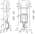
- FIG. 5A illustrates one embodiment of a horizontal poletip configuration read/write head 40A.
- This embodiment is fabricated using a free standing side wall technique such as described by Lazzari et al., "A New Thin Film Head Generation I.C. Head,” IEEE Transactions on Magnetics, Volume 25, No. 5, page 3190, 1989.
- Pole pieces 42A and 44A are spaced apart by a magnetic gap 46A. This permits the horizontal head 40A to read and write magnetic signals and to communicate these signals via coils 48A to circuitry (not shown) of its associated disk drive.
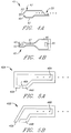
- the horizontal head 40B shown in Fig. 5B utilizes pole pieces 42B and 44B separated by a gap 46B.
- Horizontal head 40B communicates via coils 48B.
- the pole piece 42B is slanted and can be fabricated without the use of a free standing sidewall such as required for the embodiment shown in Fig. 5A.
- Figs. 6A-6F are cross-sectional views illustrating the processing steps involved in the fabrication of a preferred embodiment of the present invention incorporating the horizontal head shown in Fig. 5B.
- a seed layer 57 is first deposited by sputter deposition, for example, on a substrate 52.
- the next step is the deposition of a layer of photoresist 50 onto the substrate 52 over the seed layer 57 and then etching or otherwise forming a resist pattern having a slope 54.
- the substrate 52 represents a substrate and release layer as described in greater detail with reference to Fig. 7 below.
- a first pole piece layer 56 of NiFe, for example, and a separation layer 58 of copper (Cu), for instance, are deposited onto the seed layer 57, as is shown in Fig.
- the separation layer 58 provides separation between the two pole pieces of the head. The only requirement for the separation layer 58 is that it be of a non-magnetic material.
- the slope 54 of the resist pattern causes the layers 56 and 58 to be formed with a slope 60.
- the first pole piece layer 56 and the Cu layer 58 are sequentially plated onto the substrate 52.
- a layer 62 of a magnetic gap material is then deposited over the layers 56 and 58 after the resist pattern of the photoresist 50 is removed as is shown in Fig. 6C.
- Fig. 6D shows that the unneeded material of the magnetic gap layer 62 is then removed through a resist mask and etch step, for example (not shown), to provide a gap layer 62 covering only the slope 60 (see Fig.
- the first pole piece layer 56 determines the throat height for the resultant poletip structure 70, as is shown in Fig. 6F.
- the poletip structure 70 comprises a first pole piece formed by the NiFe layer 56 and a second pole piece formed by the NiFe layer 68 having a gap therebetween formed by the gap layer 62.
- the separation layer 58 thickness is determined by the minimum required separation distance between the first pole piece formed by NiFe layer 56 and the later deposited second pole piece 68. While Fig. 6F illustrates the gap layer 62 slanted at the angle formed by slope 60, the slanted gap layer is not restricted to the slope as shown. That is, the slope of the slanted gap layer can be at any angle between 90 degrees, i.e., perpendicular and ⁇ 70° with respect to the plane of the substrate 52.
- Figs. 6A-6F An important consideration in the process shown in Figs. 6A-6F is the material utilized for seed layer 57 required for the deposition of both pole piece layers 56 and 68. Preferably a plating process is used and a single seed layer 57 can be used for plating both pole pieces.
- the seed layer material used is magnetic, it must not be present in the magnetic gap 65 to prevent magnetically shorting the gap 65. If the seed layer is non-magnetic and deposited over the magnetic gap 65 and is greater than a fraction of a microinch, it generally should be removed to minimize the magnetic head/disk separation. If the non-magnetic seed layer is of a material suitable for use as a wear layer, the need for deposition of a separate wear layer can be eliminated.
- Fig. 7 a cross-sectional view illustrating the various process layers utilized in the fabrication of a preferred embodiment of the present invention is shown.
- One objective of the present invention is to fabricate horizontal type heads and encapsulate these heads in a suspension structure fabricated by thin film deposition of a dielectric material, such as Al2O3 (alumina), for example.
- the suspension shape is patterned around the horizontal head using conventional etching techniques well known to those in the art.
- the completed head and suspension assembly is separated from the substrate using a release or sacrificial layer between the substrate and dielectric suspension material. All processing is performed in planes parallel to the wafer substrate surface.
- a process carrier substrate 81 can be of any suitable material known to those in the art, such as alumina-titanium-carbide (AlTiC) or silicon, for example.
- a sacrificial or release layer 83 is then formed on the substrate 81.
- the release layer 83 serves several purposes.
- the release layer 83 is the sacrificial layer which is eventually dissolved to free the finished suspension-transducer assembly 80 from the substrate 81.
- the release layer 83 can also be patterned to shape a subsequently deposited wear layer.
- the release layer 83 can, for instance, be an electrically conductive material and thereby serve as a seed or plating base layer for the subsequent layers deposited utilizing plating techniques, such as the pole pieces of the transducer. Likely candidates for the release layer 83 are NiFe or Cu which could be deposited through a sputtering or plating process. A barrier layer 85 is then formed over the release layer 83.
- the barrier layer 85 similarly serves several functions in the production process.
- the barrier layer 85 is used to isolate the subsequently deposited layers from the release layer 83.
- the magnetic poletip structure 70 and head 90 formed as described with reference to Figs. 6A to 6F can be the subsequently deposited layers.
- pole pieces 71 and 73 of Fig. 7 can be formed in the same manner as discussed for the pole pieces 68 and 56, respectively, of Figs. 6A-6F.
- the barrier layer 85 serves as an etch stop to protect the pole pieces from any etchant which may be later used to dissolve the release layer 83.
- the barrier layer 85 may be used as the seed layer for plating of the pole pieces 71 and 73, as described above, for example.
- the barrier layer 85 may be used as a wear layer to protect the pole pieces during operation in close proximity to a rotating magnetic media. In this capacity, it is preferable that the barrier layer 85 be an electrically conductive material which could assist in promoting a longer lifetime in a contact recording mode. If the barrier layer 85 is not to be used also as a wear layer, it is desirable to remove it after the release layer 83 is dissolved.
- FIG. 7 A thin film deposition process for fabrication of the pole piece structure 70 utilized in the embodiment shown in Fig. 7 has been described with reference to Figs. 6A-6F. While the described process only concerned the formation of the poletips and the magnetic gap therebetween, it is understood by those skilled in the art fabrication of the poletip structure 70 is not an isolated process, but is integrated with the fabrication of the entire magnetic head 90. For example, the entire lower pole piece or lower yoke 73 is typically formed in one plating operation rather than just forming the lower poletip 56 and later forming the remainder of the lower yoke 73.
- the upper poletip 68 is formed in a separate plating step and the remainder of the upper pole piece or upper yoke 71 plated and "stitched" to the upper poletip 68 in a subsequent process step after the coil windings 77 and lead conductors 79 have been formed.
- the entire upper pole piece 71 including poletip 68 can be placed in a single process step subsequent to the plating of the coil windings 77 and lead conductors 79.
- the formation of the dielectric layer 75 including the separation layer 58 in which the coil windings 77 are embedded can be accomplished in a single step or series of steps prior to the plating of the upper poletip 68.
- a non-magnetic electrical conductive material such as Cu is utilized as the separation layer 58, it will be necessary to form the dielectric layer separately because the coil windings 77 must be embedded in an insulating material.
- a layer of a suitable dielectric material such as alumina, for example, is deposited over the magnetic transducer 70 to provide the transducer suspension assembly 80 to support the transducer 70 in sensing relationship with the magnetic media (as shown in Figs. 1 and 2).
- the suspension section 87 includes coil turns 77 and associated conductor leads 79 embedded in the layer or layers that form the suspension section 87.
- Contact studs 78 are formed in the suspension section 87 at the external termination points of the conductors 79 at the end opposite the transducer 90.
- the present invention are the use of an electrically conductive release layer 83 as the primary seed layer, with possibly a thin electrically conductive barrier layer 85 on top to provide a wear layer for the completed poletip structure 70.
- the wear layer could thereby be thin without any lapping process.
- the pole pieces 71 and 73 are preferably formed by a plated Permalloy process. A light lapping of the pole pieces may be required to insure a planar or level pole tip structure 70 from this fabrication process.
- Figs. 8A-8D perspective views of preferred embodiments of the present invention wherein the reed assembly body is fabricated in desired shapes to provide specific suspension characteristics are shown. Since the reed assembly is fabricated on a substrate with thin film technology, it is possible to locally shape and stiffen the suspension.
- the topographical shape of the suspension system can be as shown in the aforementioned Watrous USP 4,167,765 or in any of the other planar view shapes commonly used. The planar shape of the suspension should not be taken as a limiting factor in this invention.
- Fig. 8A-8D perspective views of preferred embodiments of the present invention wherein the reed assembly body is fabricated in desired shapes to provide specific suspension characteristics are shown. Since the reed assembly is fabricated on a substrate with thin film technology, it is possible to locally shape and stiffen the suspension.
- the topographical shape of the suspension system can be as shown in the aforementioned Watrous USP 4,167,765 or in any of the other planar view shapes commonly used.
- a reed assembly body 92 comprises an elongate structure having a generally rectangular (parallel piped) shape in which the suspension characteristics are determined primarily by the material and the length, width and thickness of the structure.
- the reed assembly body 94 comprises a suspension section 91 in which the width of the body is changed to form a trapezoidal section 93 necking down to the transducer section 95.
- the suspension characteristics are primarily determined by the change in width between the suspension section 91 and the transducer section 95 and the rate of width change; i.e., the length of trapezoidal section 93.
- Figs. 8C and 8D illustrate the reed assembly of Fig.
- Figs. 9A and 9B side views of the reed assembly suspension section illustrating one processing technique employed to create the localized patterning to fabricate a thin film suspension system in a plane parallel to the top plane of the process carrier substrate to effectuate the selective stiffening shown in Fig. 8D is shown.
- a release layer 100 is formed on a substrate 102.
- the thickness of the release layer 100 is varied locally to provide thinner portions 104 and thicker portions 106 to provide a mold having the desired suspension patterning in reverse relief. This is accomplished, for instance, by plating two layers of the release material.
- the second layer is patterned by photoresist, or by plating a thick layer of the release material and then locally milling or etching areas of the release layer 100. This approach is also useful for creating the ABS contour mold.
- a suspension material 108 is deposited onto the release layer 100 mold to selectively vary the thickness of the suspension material 108.
- the suspension material 108 when separated from the release layer 100, becomes the suspension portion 110 of a thin film transducer-suspension reed assembly as is shown in Fig. 9B.
- a second approach is illustrated in Figs. 9C and 9D to locally etch or pattern a layer of suspension material 111 deposited onto a release layer 112.
- the release layer 112 in formed by depositing a release material onto a substrate 114.
- the top of the suspension layer 110 is patterned with photoresist and etched at portions 116 to provide a suspension layer that is flexible along its length.
- the top of the suspension layer is etched at portions 116 while it is still attached to the release layer 112 and the substrate 114.
- a contoured suspension portion 118 is obtained.
- the assembly 120 includes a horizontal transducer 122 which can be produced according to the sidewall process described by Lazzari referenced herein above.
- a wear layer 124 and coils 126 can be produced in the same process.
- Conductor leads 128 and stud pads 130 can be provided as discussed with reference to Fig. 7 along the length of a thin film suspension section 132.
- the suspension section 132 can include one or more stiffening portions 134 and 136 to support the transducer 122, and a contoured air bearing surface portion 136 which will control the flying height of the transducer 122.
- the conductor leads 128 are preferably plated copper.
- the conductor leads 128 are routed along the suspension structure 132 to the stud pads 130.
- the conductor leads are configured in a stripline arrangement since the suspension 132 is thin and the stress symmetry required is compatible with a stripline design.
- the suspension section 132 is preferably produced by depositing alumina or other suitable material onto the release layer of Fig. 9A. Standard stud and pad technology is used to produce the stud pad 130 to complete the thin film head/suspension reed assembly 120. A thick deposition of alumina can be used to ensure complete encapsulation of the transducer 122 followed by a lapping operation to planarize the top surface of the transducer-suspension assembly.
- the alumina suspension material is preferably sputtered to a thickness of from 20 to 50 micrometers.
- the suspension shape is formed by etching the overcoat and undercoat of alumina. After the suspension shape is formed, the release layer is dissolved to free the head/suspension devices for use.
- the described head-suspension structure embodiment is suitable for longitudinal recording and is resistant to wear along its poletips and the air bearing surface contours.
- This structure can be batch processed in planes parallel to the starting wafer surface and allows for anisotropic stiffening for maximum actuator bandwidth. Production of these suspension/transducer assemblies is facilitated since an extensive lap process is avoided.
- a transducer may be produced onto the wafer such as is described in U.S. Patent 4,190,872, assigned to the assignee of the present invention.
- the wafer may be made of material such as is the subject matter of the Jacobs U.S. Patent 4,251,841, entitled “Magnetic Head Slider Assembly” and assigned to the assignee of the present invention.
- suspension portions of the present invention are preferably composed of sputter-deposited alumina, it is recognized that other methods of deposition may be employed and that other materials may be utilized, including other suitable oxides, nitrides, carbonides, glasses, amorphous carbon, diamond-like carbon or laminated combinations of suitable conducting and insulating materials.
- the suspension section according to the preferred embodiments could be a dual layer of a polyimide material and a metal layer deposited thereon to provide sufficient resiliency and stiffness as required by a suspension assembly. It should be noted that the suspension assembly could be produced in a single layer if the correct thickness and stiffness were obtained in the single layer. It is also well understood that many electrically conductive materials are available to form the conductive circuitry and the transducer leads.
- the present invention also includes contact recording wherein the air bearing surface is any suitable surface that can be placed in contact with the media during operation. It should also be evident that the linear actuator could be a rotary styled actuator without departing from the present invention.
Landscapes
- Engineering & Computer Science (AREA)
- Manufacturing & Machinery (AREA)
- Physics & Mathematics (AREA)
- Electromagnetism (AREA)
- Magnetic Heads (AREA)
- Supporting Of Heads In Record-Carrier Devices (AREA)
- Adjustment Of The Magnetic Head Position Track Following On Tapes (AREA)
Applications Claiming Priority (2)
| Application Number | Priority Date | Filing Date | Title |
|---|---|---|---|
| US229093A | 1993-01-08 | 1993-01-08 | |
| US2290 | 1993-01-08 |
Publications (2)
| Publication Number | Publication Date |
|---|---|
| EP0605984A2 true EP0605984A2 (fr) | 1994-07-13 |
| EP0605984A3 EP0605984A3 (fr) | 1996-01-31 |
Family
ID=21700098
Family Applications (1)
| Application Number | Title | Priority Date | Filing Date |
|---|---|---|---|
| EP93310269A Withdrawn EP0605984A3 (fr) | 1993-01-08 | 1993-12-17 | Structure unitaire de transducteur magnétique et de suspension. |
Country Status (7)
| Country | Link |
|---|---|
| US (1) | US5454158A (fr) |
| EP (1) | EP0605984A3 (fr) |
| JP (1) | JP2577527B2 (fr) |
| KR (1) | KR0129105B1 (fr) |
| CN (1) | CN1058799C (fr) |
| MY (1) | MY121535A (fr) |
| SG (1) | SG44438A1 (fr) |
Cited By (2)
| Publication number | Priority date | Publication date | Assignee | Title |
|---|---|---|---|---|
| US5687479A (en) * | 1994-04-15 | 1997-11-18 | Hutchinson Technology Incorporated | Electrical trace interconnect assembly |
| US6493182B1 (en) * | 1997-10-08 | 2002-12-10 | Tdk Corporation | Magnetic head |
Families Citing this family (34)
| Publication number | Priority date | Publication date | Assignee | Title |
|---|---|---|---|---|
| JP2721783B2 (ja) * | 1992-08-19 | 1998-03-04 | インターナショナル・ビジネス・マシーンズ・コーポレイション | 薄膜磁気ヘッド変換器/懸架部の組合せシステム並びにその製造方法 |
| TW243530B (en) * | 1992-12-30 | 1995-03-21 | Ibm | Magnetoresistive sensor with improved microtrack profile for improved servo-positioning precision |
| US20020053734A1 (en) | 1993-11-16 | 2002-05-09 | Formfactor, Inc. | Probe card assembly and kit, and methods of making same |
| US7073254B2 (en) | 1993-11-16 | 2006-07-11 | Formfactor, Inc. | Method for mounting a plurality of spring contact elements |
| JP3354302B2 (ja) * | 1994-07-27 | 2002-12-09 | 日本メクトロン株式会社 | 磁気ヘッド用サスペンションの製造法 |
| US5754377A (en) * | 1994-08-26 | 1998-05-19 | Aiwa Research And Development, Inc. | Thin film magnetic head including an elevated gap structure |
| US6091581A (en) * | 1994-08-26 | 2000-07-18 | Aiwa Co., Ltd. | Thin film magnetic head including a separately deposited diamond-like carbon gap structure and magnetic control wells |
| JP2682472B2 (ja) * | 1994-10-31 | 1997-11-26 | 日本電気株式会社 | 磁気ヘッド及びこの製造方法 |
| US5859105A (en) * | 1997-02-11 | 1999-01-12 | Johnson Matthey, Inc. | Organosilicon-containing compositions capable of rapid curing at low temperature |
| US5663854A (en) * | 1995-06-07 | 1997-09-02 | International Business Machines Corporation | Prebent ceramic suspension |
| KR100370759B1 (ko) * | 1995-10-20 | 2003-03-26 | 삼성전자 주식회사 | 하드디스크드라이브의디스크장치 |
| JP2783231B2 (ja) * | 1995-12-28 | 1998-08-06 | 日本電気株式会社 | 接触式磁気ディスク装置 |
| DE69708474T2 (de) * | 1996-02-12 | 2002-05-08 | Read-Rite Corp., Milpitas | Biegungsvorrichtung mit Leiterbahn für eine Magnetkopfaufhängungseinheit |
| US8033838B2 (en) | 1996-02-21 | 2011-10-11 | Formfactor, Inc. | Microelectronic contact structure |
| JP3107746B2 (ja) * | 1996-04-27 | 2000-11-13 | 日本メクトロン株式会社 | 磁気ヘッド用サスペンションの製造法 |
| JPH10261212A (ja) * | 1996-09-27 | 1998-09-29 | Nippon Mektron Ltd | 回路配線付き磁気ヘッド用サスペンションの製造法 |
| US5757591A (en) | 1996-11-25 | 1998-05-26 | International Business Machines Corporation | Magnetoresistive read/inductive write magnetic head assembly fabricated with silicon on hard insulator for improved durability and electrostatic discharge protection and method for manufacturing same |
| US6147839A (en) * | 1996-12-23 | 2000-11-14 | Hutchinson Technology, Inc. | Head suspension with outriggers extending across a spring region |
| US5900728A (en) * | 1997-03-20 | 1999-05-04 | International Business Machines Corporation | Alternating current magnetic force microscopy system with probe having integrated coil |
| US5900729A (en) * | 1997-03-20 | 1999-05-04 | International Business Machines Corporation | Magnetic force microscopy probe with integrated coil |
| US5751517A (en) * | 1997-04-11 | 1998-05-12 | Western Digital Corporation | Air bearing slider having debris removing channels |
| US5924187A (en) * | 1998-01-06 | 1999-07-20 | Hutchinson Technology Incorporated | Integrated lead head suspension assembly having an etched laminated load beam and flexure with deposited conductors |
| DE69826242D1 (de) * | 1998-05-05 | 2004-10-21 | St Microelectronics Srl | Herstellungsverfahren für eine Festplatten-Lese/Schreibeinheit, mit mikrometrischer Betätigung |
| US6093083A (en) * | 1998-05-06 | 2000-07-25 | Advanced Imaging, Inc. | Row carrier for precision lapping of disk drive heads and for handling of heads during the slider fab operation |
| DE10020374A1 (de) * | 1999-07-02 | 2001-01-25 | Fujitsu Ltd | Kopfbaugruppe einer Plattenvorrichtung mit einem Kopf-IC-Chip, der durch Ultraschallbonden an eine Aufhängung montiert ist |
| DE69931370T2 (de) * | 1999-10-01 | 2007-02-01 | Stmicroelectronics S.R.L., Agrate Brianza | Verfahren zur Herstellung eines aufgehängten Elements für elektrische Verbindungen zwischen zwei Teilen eines Micromechanismus, welche relativ zueinander beweglich sind |
| US6501619B1 (en) * | 2000-04-27 | 2002-12-31 | Shipley Company, L.L.C. | Inductive magnetic recording head having inclined magnetic read/write pole and method of making same |
| JP3866512B2 (ja) * | 2000-12-26 | 2007-01-10 | アルプス電気株式会社 | 垂直磁気記録ヘッドの製造方法 |
| US7005242B2 (en) * | 2002-03-22 | 2006-02-28 | International Business Machines Corporation | Magnetic head and method of making the same using an etch-stop layer for removing portions of the capping layer |
| US7369369B1 (en) * | 2003-04-03 | 2008-05-06 | Meyer Dallas W | Bidirectional micropositioning recording head for a magnetic storage device |
| US7538983B1 (en) | 2003-07-29 | 2009-05-26 | Meyer Dallas W | Micropositioner recording head for a magnetic storage device |
| US8066547B1 (en) | 2003-11-18 | 2011-11-29 | Veeco Instruments Inc. | Bridge row tool |
| US7397633B2 (en) * | 2005-03-01 | 2008-07-08 | Seagate Technology, Llc | Writer structure with assisted bias |
| US8279559B1 (en) | 2009-01-02 | 2012-10-02 | Meyer Dallas W | Process for creating discrete track magnetic recording media including an apparatus having a stylus selectively applying stress to a surface of the recording media |
Family Cites Families (28)
| Publication number | Priority date | Publication date | Assignee | Title |
|---|---|---|---|---|
| GB1342495A (en) * | 1971-03-13 | 1974-01-03 | Ibm | Transducer arms for magnetic disc recording and or reproducing apparatus |
| GB1364863A (en) * | 1971-05-26 | 1974-08-29 | Int Computers Ltd | Magnetic heads |
| US4167765A (en) * | 1978-07-27 | 1979-09-11 | International Business Machines Corporation | Transducer suspension mount apparatus |
| US4190872A (en) * | 1978-12-21 | 1980-02-26 | International Business Machines Corporation | Thin film inductive transducer |
| US4251841A (en) * | 1979-06-01 | 1981-02-17 | International Business Machines Corporation | Magnetic head slider assembly |
| JPS5674812A (en) * | 1979-11-26 | 1981-06-20 | Nippon Telegr & Teleph Corp <Ntt> | Magnetic head assembly |
| EP0032230A3 (fr) * | 1980-01-14 | 1982-01-13 | Siemens Aktiengesellschaft | Transducteur magnétique intégré et procédé pour sa fabrication |
| JPS5979417A (ja) * | 1982-10-28 | 1984-05-08 | Sony Corp | 磁気ヘツド装置 |
| JPS59213066A (ja) * | 1983-05-18 | 1984-12-01 | Hitachi Ltd | 磁気ヘツド素子用支持体 |
| DE3376036D1 (en) * | 1983-08-17 | 1988-04-21 | Ibm Deutschland | Method of manufacturing a magnetic head flying body |
| JPH06101099B2 (ja) * | 1984-12-21 | 1994-12-12 | 日本電信電話株式会社 | 薄膜ヘツド |
| JP2513205B2 (ja) * | 1987-02-04 | 1996-07-03 | ソニー株式会社 | 複合磁気ヘツド |
| EP0311854A1 (fr) * | 1987-10-16 | 1989-04-19 | Siemens Aktiengesellschaft | Tête magnétique à film mince à structure en couches pour magnétisation perpendiculaire |
| JP2585400B2 (ja) * | 1988-03-23 | 1997-02-26 | 株式会社日立製作所 | 磁気デイスク装置 |
| JPH01277380A (ja) * | 1988-04-22 | 1989-11-07 | Internatl Business Mach Corp <Ibm> | ヘツド・サスペンシヨン・ロードビーム |
| US5166845A (en) * | 1989-02-22 | 1992-11-24 | Iomega Corporation | Integrated read/write heads, flexure assembly and air-bearing structure on common unitary substrate |
| JPH0782630B2 (ja) * | 1989-02-28 | 1995-09-06 | 三菱電機株式会社 | 薄膜磁気ヘッド装置 |
| JP2713762B2 (ja) * | 1989-05-03 | 1998-02-16 | ティーディーケイ株式会社 | ヘッド支持装置 |
| US5073242A (en) * | 1989-11-27 | 1991-12-17 | Censtor Corp. | Method of making integrated magnetic read/write head/flexure/conductor structure |
| US5041932A (en) * | 1989-11-27 | 1991-08-20 | Censtor Corp. | Integrated magnetic read/write head/flexure/conductor structure |
| US5111351A (en) * | 1989-11-27 | 1992-05-05 | Censtor Corp. | Integrated magnetic read/write head/flexure/conductor structure |
| JPH04271005A (ja) * | 1991-01-22 | 1992-09-28 | Mitsubishi Electric Corp | 薄膜磁気ヘッドの製造方法 |
| JPH04268204A (ja) * | 1991-02-22 | 1992-09-24 | Fujitsu Ltd | 磁気ヘッドの製造方法 |
| JPH04289508A (ja) * | 1991-03-04 | 1992-10-14 | Mitsubishi Electric Corp | 薄膜磁気ヘッドの製法 |
| ATE157189T1 (de) * | 1991-04-10 | 1997-09-15 | Censtor Corp | Verschleissarmer kopf zur wiedergabe und aufnahme mit berührung auf einem magnetischen träger |
| CA2047563C (fr) * | 1991-06-11 | 1993-08-17 | Harold J. Hamilton | Element conducteur magnetique integre a tete de lecture et d'ecriture |
| EP0576680B1 (fr) * | 1992-01-20 | 2004-03-31 | Fujitsu Limited | Ensemble tete magnetique, sa production et unite de disque magnetique |
| JP2721783B2 (ja) * | 1992-08-19 | 1998-03-04 | インターナショナル・ビジネス・マシーンズ・コーポレイション | 薄膜磁気ヘッド変換器/懸架部の組合せシステム並びにその製造方法 |
-
1993
- 1993-12-08 KR KR1019930026816A patent/KR0129105B1/ko not_active Expired - Fee Related
- 1993-12-08 MY MYPI93002621A patent/MY121535A/en unknown
- 1993-12-08 CN CN93120810A patent/CN1058799C/zh not_active Expired - Fee Related
- 1993-12-15 JP JP5315556A patent/JP2577527B2/ja not_active Expired - Fee Related
- 1993-12-17 EP EP93310269A patent/EP0605984A3/fr not_active Withdrawn
- 1993-12-17 SG SG1996000392A patent/SG44438A1/en unknown
-
1994
- 1994-07-01 US US08/270,104 patent/US5454158A/en not_active Expired - Lifetime
Cited By (2)
| Publication number | Priority date | Publication date | Assignee | Title |
|---|---|---|---|---|
| US5687479A (en) * | 1994-04-15 | 1997-11-18 | Hutchinson Technology Incorporated | Electrical trace interconnect assembly |
| US6493182B1 (en) * | 1997-10-08 | 2002-12-10 | Tdk Corporation | Magnetic head |
Also Published As
| Publication number | Publication date |
|---|---|
| JP2577527B2 (ja) | 1997-02-05 |
| MY121535A (en) | 2006-02-28 |
| KR940018854A (ko) | 1994-08-19 |
| EP0605984A3 (fr) | 1996-01-31 |
| US5454158A (en) | 1995-10-03 |
| JPH06236537A (ja) | 1994-08-23 |
| CN1089381A (zh) | 1994-07-13 |
| KR0129105B1 (ko) | 1998-04-18 |
| SG44438A1 (en) | 1997-12-19 |
| CN1058799C (zh) | 2000-11-22 |
Similar Documents
| Publication | Publication Date | Title |
|---|---|---|
| US5454158A (en) | Method of making integral transducer-suspension assemblies for longitudinal recording | |
| US5560097A (en) | Method of making a integrated transducer-suspension assembly for vertical recording | |
| US5742998A (en) | Method of making integrated suspension magnetic head structures for longitudinal recording | |
| EP0568257B1 (fr) | Tête pour transférer les données | |
| KR100290936B1 (ko) | 자기헤드장치및그제조방법 | |
| US5742452A (en) | Low mass magnetic recording head and suspension | |
| US20010001588A1 (en) | Integrated lead head supension assembly having an etched laminated load beam and flexure with deposited conductors | |
| US5486968A (en) | Method and apparatus for simultaneous write head planarization and lead routing | |
| JP2003030803A (ja) | 磁気ヘッド組立体およびその製造方法 | |
| US5745979A (en) | Magnetic head for recording with ultra low force | |
| KR0178305B1 (ko) | 박막 자기 변환기의 수직 갭 형성방법 | |
| WO1998014937A1 (fr) | Suspension a conducteurs integres a impedance reglee | |
| US7336445B2 (en) | Conductive stud for magnetic recording devices and method of making the same | |
| EP0330398A2 (fr) | Tête de lecture magnétique | |
| KR0129107B1 (ko) | 극히 약한 힘으로 기록하는 자기 헤드 및 그것의 가공 방법 | |
| KR0129106B1 (ko) | 종방향 기록용 집적 트랜스듀서-서스펜션 구조 |
Legal Events
| Date | Code | Title | Description |
|---|---|---|---|
| PUAI | Public reference made under article 153(3) epc to a published international application that has entered the european phase |
Free format text: ORIGINAL CODE: 0009012 |
|
| AK | Designated contracting states |
Kind code of ref document: A2 Designated state(s): DE FR GB |
|
| 17P | Request for examination filed |
Effective date: 19941125 |
|
| PUAL | Search report despatched |
Free format text: ORIGINAL CODE: 0009013 |
|
| AK | Designated contracting states |
Kind code of ref document: A3 Designated state(s): DE FR GB |
|
| 17Q | First examination report despatched |
Effective date: 19971210 |
|
| STAA | Information on the status of an ep patent application or granted ep patent |
Free format text: STATUS: THE APPLICATION IS DEEMED TO BE WITHDRAWN |
|
| 18D | Application deemed to be withdrawn |
Effective date: 19980421 |