EP0606078A2 - Sortie d'air pour installation de traitement d'air - Google Patents
Sortie d'air pour installation de traitement d'air Download PDFInfo
- Publication number
- EP0606078A2 EP0606078A2 EP94100114A EP94100114A EP0606078A2 EP 0606078 A2 EP0606078 A2 EP 0606078A2 EP 94100114 A EP94100114 A EP 94100114A EP 94100114 A EP94100114 A EP 94100114A EP 0606078 A2 EP0606078 A2 EP 0606078A2
- Authority
- EP
- European Patent Office
- Prior art keywords
- guide element
- air passage
- air
- passage according
- source air
- Prior art date
- Legal status (The legal status is an assumption and is not a legal conclusion. Google has not performed a legal analysis and makes no representation as to the accuracy of the status listed.)
- Granted
Links
Images


Classifications
-
- F—MECHANICAL ENGINEERING; LIGHTING; HEATING; WEAPONS; BLASTING
- F24—HEATING; RANGES; VENTILATING
- F24F—AIR-CONDITIONING; AIR-HUMIDIFICATION; VENTILATION; USE OF AIR CURRENTS FOR SCREENING
- F24F13/00—Details common to, or for air-conditioning, air-humidification, ventilation or use of air currents for screening
- F24F13/02—Ducting arrangements
- F24F13/06—Outlets for directing or distributing air into rooms or spaces, e.g. ceiling air diffuser
- F24F13/068—Outlets for directing or distributing air into rooms or spaces, e.g. ceiling air diffuser formed as perforated walls, ceilings or floors
Definitions
- the invention relates to a source air passage for ventilation systems, which can be connected at one end to an air duct system via a supply air connection.
- the source air passage consists of an outer air-permeable jacket and an inner air-permeable jacket arranged concentrically therein. At least one horizontal diaphragm ring is arranged in the source air passage.
- Such air outlets are generally known and are usually installed standing on the floor, so that the supply air from the air outlet to the people within the room to be air conditioned only has to travel a relatively short distance.
- This route leads in particular in high and polluted industrial halls through the relatively lightly loaded area near the floor. In this way, the supply air is mixed relatively little with polluted indoor air before it is inhaled by the people. Since there is usually a coupling of heat and pollutant origin in industrial halls, the released pollutants rise in the convective heat flow to the roof of the hall, where they are captured by the exhaust system.
- the source air passages In order not to disturb this material flow, the source air passages must supply the supply air to the lounge area at a low air speed and add volume to the rising material flow, so that there is no recirculation of polluted indoor air from higher hall areas into the work or lounge area.
- a source air passage of the generic type is known from DE-OS 40 37 287.
- the supply air inside the cylindrical, perforated jacket is evenly deflected by horizontal and vertical internals consisting of perforated sheets and fed horizontally to the room to be air-conditioned.
- the supply air receives a velocity component directed towards the floor due to the higher density due to the lower temperature after the horizontal outlet from the source air passage. This is reinforced by the Coanda effect of the floor. This causes the supply air layer to constrict with a significant increase in air speed by a factor of 2 to 3. Drafts and increased recirculation of polluted indoor air are the result.
- the invention has for its object to design the generic source air passage so that drafts are avoided and that heating of the room to be air-conditioned is possible.
- the flow behavior of the supply air emerging from the source air passage can be influenced differently, depending on whether the temperature of the supply air is below or above the temperature of the room air.
- the flow cross-section of the tubular guide element can be reduced to zero, which creates an air flow at the outlet from the source air passage, the outlet direction of which is directed downwards and the speed of which increases significantly from top to bottom. This counteracts the rise of the warmer supply air.
- the source air passage consists of an outer air-permeable cylindrical jacket 1 and an inner air-permeable cylindrical jacket 2 arranged concentrically therein, both of which are preferably made of a perforated plate.
- the source air passage is closed at the top except for the cross section for a supply air connection 3, which can be connected to an air duct network (not shown).
- the source air passage is also provided with a closed floor 4 and is on the floor 5 of the hall to be air-conditioned or the other room to be air-conditioned.
- a flap 7 is attached in order to change its flow cross-section, with which the tubular guide element 6 can also be opened or closed completely.
- the flap 7 is pivotally mounted in the tubular guide element 6 via an axis and can be pivoted mechanically with the aid of a lever or by means of an electrically or pneumatically acting drive 8 acting on the axis.
- a swirl vane insert 9 is arranged in the lower part of the tubular guide element 6 in order to generate turbulence.
- the swirl vane insert 9 can be vertically displaceable to shift its effective range.
- the blades of the swirl blade insert 9 can also be designed to be rotatable in their angular position in order to change the swirl strength.
- diaphragm rings 10, 11 are arranged horizontally above the tubular guide element and have a central through opening and an outer ring surface.
- the ring surface of the upper diaphragm ring 10 is closed, while that of the lower diaphragm ring 11, which is designed as a pinhole ring, has holes.
- a further diaphragm ring 12 is arranged horizontally, which extends over the intermediate space in such a way that it divides it into two annular chambers 13, 14 lying one above the other.
- This further aperture ring 12 is perforated in the first exemplary embodiment described here.
- the second exemplary embodiment shown in FIGS. 3 to 5 differs from the previously described first exemplary embodiment essentially in that the function of the flap 7 and that of the diaphragm ring 12 is taken over by two horizontal disks 15, 16 arranged one above the other. These divide the annular space between the tubular guide element 6 and the inner jacket 2 into the annular chambers 13 and 14 and the tubular guide element 6 into an upper and a lower tubular guide element section. Openings 17 in the rotatably mounted upper disc 15 correspond to openings 18 in the rigidly arranged disc 16, so that, depending on the rotational position of the disc 15, the openings 17 are more or less aligned with the openings 18 or the openings 17 and 18 with areas of the openings which are not open Disks 16 and 15 are blocked.
- the tubular guide element 6 ' is combined from an upper section which is flared upwards and a cylindrical lower section. Disks 15 'and 16' are arranged horizontally between the two sections.
- the upper disk 15 'and 16' is not congruent.
- the disk 15 ' is rotatably mounted, so that openings 17' in the upper disk 15 'are more or less flush with openings 18' and / or 19 'or are blocked with areas of the disks 15' or 16 'which are free of openings. With fully closed openings 18 'through the segments of the disc 15', the openings 19 'of the disc 16' are fully open.
- the tubular guide element 6 ′′ is conically narrowed from bottom to top.
- the disks 15 ′′ and 16 ′′ dividing the annular space into the annular chambers 13 and 14 are designed in the form of a gear wheel, so that the tooth-gap-shaped openings 17 ′′ in the rotatably mounted disc 15 ′′ with the tooth-gap-shaped openings 18 ′′ in the rigid disk 16 ′ 'can be aligned more or less or can be blocked by tooth-shaped areas of the disk 16''or15''.
- the supply air supplied via the supply air connection 3 enters the interior of the inner casing 2 and exits through the outer casing 1 into the hall to be air-conditioned.
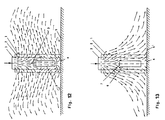
- the air flow can be influenced in such a way that the flow-shaped cross-section of the tubular guide element 6, 6 ', 6' 'can be influenced in such a way that the flow patterns shown in FIGS. 12 and 13 are established.
- the flow cross-section of the tubular guide element 6 is released so that part of the supply air supplied flows vertically, while the rest of the supply air exits radially through the outer jacket 1 (FIG. 12).
- the partial flow flowing through the tubular guide element 6 is deflected at the bottom 4 of the source air passage, enters the lower annular chamber 14 and emerges from the lower part of the outer jacket 1. In this way, the total supply air emerging from the source air passage receives the slightly upward flow direction shown in FIG. Since the supply air is colder than the room air, the supply air sinks into the living area due to the higher density.
- the supply air is too low compared to the room air, to avoid a reduction in comfort, it makes sense to overlay the supply air with a swirl of adjustable size in order to adjust the supply air temperature more quickly to the room air temperature.
- This swirl is generated with the help of the swirl vane insert 9 arranged in the tubular guide element 6.
- the swirl blade insert 9 would undesirably reduce the penetration depth of the supply air. However, this is prevented by closing the tubular guide element 6, as a result of which the swirl is eliminated.
- the tubular guide element 6 is blocked so that it is not flowed through. As shown in FIG. 13, an air flow with a strongly downward air outlet direction and an increasing air speed in the direction of the floor 5 is thereby generated on the outside of the source air passage. This counteracts a rapid rise in the warm supply air. The resulting higher room air velocities can be accepted as the warmer supply air is not perceived as a draft during heating and the heating process usually takes place before starting work. If the supply air temperature in summer is higher than the room air temperature, the blow-out characteristic according to FIG. 13 is also selected. In this case, higher air speeds are not harmful at high indoor air temperatures, but are even desirable.
Landscapes
- Engineering & Computer Science (AREA)
- Chemical & Material Sciences (AREA)
- Combustion & Propulsion (AREA)
- Mechanical Engineering (AREA)
- General Engineering & Computer Science (AREA)
- Duct Arrangements (AREA)
- Treating Waste Gases (AREA)
- Ventilation (AREA)
- Air-Flow Control Members (AREA)
Applications Claiming Priority (2)
| Application Number | Priority Date | Filing Date | Title |
|---|---|---|---|
| DE4300300 | 1993-01-08 | ||
| DE4300300 | 1993-01-08 |
Publications (3)
| Publication Number | Publication Date |
|---|---|
| EP0606078A2 true EP0606078A2 (fr) | 1994-07-13 |
| EP0606078A3 EP0606078A3 (fr) | 1995-01-25 |
| EP0606078B1 EP0606078B1 (fr) | 1998-04-01 |
Family
ID=6477867
Family Applications (1)
| Application Number | Title | Priority Date | Filing Date |
|---|---|---|---|
| EP94100114A Expired - Lifetime EP0606078B1 (fr) | 1993-01-08 | 1994-01-05 | Sortie d'air pour installation de traitement d'air |
Country Status (5)
| Country | Link |
|---|---|
| US (1) | US5360373A (fr) |
| EP (1) | EP0606078B1 (fr) |
| AT (1) | ATE164667T1 (fr) |
| DE (1) | DE59405548D1 (fr) |
| ES (1) | ES2115085T3 (fr) |
Cited By (4)
| Publication number | Priority date | Publication date | Assignee | Title |
|---|---|---|---|---|
| EP0683361A2 (fr) | 1994-05-20 | 1995-11-22 | Hartmut Bree | Sortie d'air |
| ITVA20130008A1 (it) * | 2013-02-07 | 2014-08-08 | Lino Alioli | Sistema di diffusione aria calda per complementi di arredo da esterni |
| EP2896905A1 (fr) * | 2014-01-21 | 2015-07-22 | Halton OY | Dispositif de distribution d'air |
| EP3150936A1 (fr) * | 2015-09-30 | 2017-04-05 | LTG Aktiengesellschaft | Sortie d'air et son procede de fonctionnement |
Families Citing this family (4)
| Publication number | Priority date | Publication date | Assignee | Title |
|---|---|---|---|---|
| ES2160448B1 (es) * | 1998-08-13 | 2002-05-16 | Bsh Fabricacion Sa | Acondicionador de aire movil. |
| DE10149909B4 (de) * | 2001-10-10 | 2005-07-21 | Schako Klima Luft Ferdinand Schad Kg Zweigniederlassung Kolbingen | Luftauslass |
| US7641125B2 (en) * | 2005-04-29 | 2010-01-05 | E.H. Price Ltd. | Variable air volume ceiling diffuser |
| US11077459B2 (en) * | 2014-05-29 | 2021-08-03 | Global Finishing Solutions Llc | Directional air apparatuses, system, and methods of using the same |
Family Cites Families (8)
| Publication number | Priority date | Publication date | Assignee | Title |
|---|---|---|---|---|
| NL165834C (nl) * | 1972-06-26 | 1981-05-15 | Treffers Tech Adviesbureau | Luchtuitstroomkast voor een luchtconditioneerinrichting. |
| DE2718760A1 (de) * | 1977-04-27 | 1978-11-02 | Mabag Luft & Klimatechnik | Luftauslass fuer lueftungs- und/oder klimatisierungssysteme |
| SU840608A2 (ru) * | 1979-09-06 | 1981-06-23 | Предприятие П/Я В-8843 | Воздухораспределитель плафонногоТипА |
| DE3017397C2 (de) * | 1980-05-07 | 1982-09-02 | Turbon-Tunzini Klimatechnik GmbH, 5060 Bergisch Gladbach | Luftauslaß |
| DE3304151C2 (de) * | 1983-02-08 | 1986-04-30 | Kessler & Luch Gmbh, 6300 Giessen | Luftauslaß |
| JP2571774B2 (ja) * | 1987-01-08 | 1997-01-16 | 株式会社 大氣社 | 空調用空気吹出器 |
| SE504421C2 (sv) * | 1990-03-29 | 1997-02-03 | Mats Kronfaelt | Tilluftsdon där tilluft valbart kan tillföras lokal genom ett högimpulsdon alternativt ett låghastighetsdon |
| US5033362A (en) * | 1990-08-30 | 1991-07-23 | James E. Huckestein Inc. | Air distribution outlet |
-
1993
- 1993-11-19 US US08/154,845 patent/US5360373A/en not_active Expired - Fee Related
-
1994
- 1994-01-05 AT AT94100114T patent/ATE164667T1/de not_active IP Right Cessation
- 1994-01-05 EP EP94100114A patent/EP0606078B1/fr not_active Expired - Lifetime
- 1994-01-05 ES ES94100114T patent/ES2115085T3/es not_active Expired - Lifetime
- 1994-01-05 DE DE59405548T patent/DE59405548D1/de not_active Expired - Lifetime
Cited By (5)
| Publication number | Priority date | Publication date | Assignee | Title |
|---|---|---|---|---|
| EP0683361A2 (fr) | 1994-05-20 | 1995-11-22 | Hartmut Bree | Sortie d'air |
| ITVA20130008A1 (it) * | 2013-02-07 | 2014-08-08 | Lino Alioli | Sistema di diffusione aria calda per complementi di arredo da esterni |
| EP2896905A1 (fr) * | 2014-01-21 | 2015-07-22 | Halton OY | Dispositif de distribution d'air |
| US10677491B2 (en) | 2014-01-21 | 2020-06-09 | Halton Oy | Air distribution device |
| EP3150936A1 (fr) * | 2015-09-30 | 2017-04-05 | LTG Aktiengesellschaft | Sortie d'air et son procede de fonctionnement |
Also Published As
| Publication number | Publication date |
|---|---|
| DE59405548D1 (de) | 1998-05-07 |
| ES2115085T3 (es) | 1998-06-16 |
| EP0606078B1 (fr) | 1998-04-01 |
| US5360373A (en) | 1994-11-01 |
| EP0606078A3 (fr) | 1995-01-25 |
| ATE164667T1 (de) | 1998-04-15 |
Similar Documents
| Publication | Publication Date | Title |
|---|---|---|
| DE3644567C2 (de) | Verfahren zum Einblasen von Zuluft in einen Raum | |
| DE102017115012B3 (de) | Belüftungskanal für eine Lüftungsvorrichtung eines Kraftfahrzeugs | |
| DE102008044874A1 (de) | Klimagerät | |
| EP1130331B1 (fr) | Procédé et dispositif de ventilation et de climatisation d'un local | |
| EP0606078A2 (fr) | Sortie d'air pour installation de traitement d'air | |
| DE69208663T2 (de) | Radiallüfter | |
| DE2847017C2 (de) | Zuluftauslaß für die Decke von zu belüftenden und zu klimatisierenden Räumen | |
| DE4417715C1 (de) | Luftauslaß | |
| DD142469A5 (de) | Lufteinblaskonstruktion | |
| DE19855497B4 (de) | Bodenquell-Luftkonvektor | |
| DE4400040A1 (de) | Quelluftdurchlaß für raumlufttechnische Anlagen | |
| EP0490135B1 (fr) | Dispositif pour introduire de l'air dans des locaux et salles et méthode pour sa mise en service | |
| DE4210807C2 (de) | Luftdurchlaß | |
| DE3204613A1 (de) | Gitterfoermige zuluftauslassvorrichtung fuer die belueftung oder beheizung eines raumes | |
| DE3322075C2 (de) | Gerät zum Temperieren der Luft innerhalb eines Raumes | |
| DE202011001768U1 (de) | Zuluftverteiler | |
| DE102004033337B3 (de) | Klimatisierungsvorrichtung mit einer Drosselvorrichtung | |
| EP1496318B1 (fr) | Dispositif de sortie d'air pour les plafonds | |
| DE3535152C2 (fr) | ||
| EP0601440B1 (fr) | Sortie d'air | |
| DE19832515B4 (de) | Quellluftauslass | |
| DE29518108U1 (de) | Gerät zur Belüftung von Räumen | |
| EP1304531B1 (fr) | Sortie d'air | |
| DE2735643A1 (de) | Luftauslass fuer die klimatisierung von aufenthaltsraeumen | |
| DE3731375A1 (de) | Klimaanlage mit quelluftauslass |
Legal Events
| Date | Code | Title | Description |
|---|---|---|---|
| PUAI | Public reference made under article 153(3) epc to a published international application that has entered the european phase |
Free format text: ORIGINAL CODE: 0009012 |
|
| AK | Designated contracting states |
Kind code of ref document: A2 Designated state(s): AT BE CH DE ES FR GB IT LI NL PT SE |
|
| PUAL | Search report despatched |
Free format text: ORIGINAL CODE: 0009013 |
|
| AK | Designated contracting states |
Kind code of ref document: A3 Designated state(s): AT BE CH DE ES FR GB IT LI NL PT SE |
|
| 17P | Request for examination filed |
Effective date: 19950202 |
|
| 17Q | First examination report despatched |
Effective date: 19960729 |
|
| GRAG | Despatch of communication of intention to grant |
Free format text: ORIGINAL CODE: EPIDOS AGRA |
|
| GRAG | Despatch of communication of intention to grant |
Free format text: ORIGINAL CODE: EPIDOS AGRA |
|
| GRAH | Despatch of communication of intention to grant a patent |
Free format text: ORIGINAL CODE: EPIDOS IGRA |
|
| GRAH | Despatch of communication of intention to grant a patent |
Free format text: ORIGINAL CODE: EPIDOS IGRA |
|
| GRAA | (expected) grant |
Free format text: ORIGINAL CODE: 0009210 |
|
| ITF | It: translation for a ep patent filed | ||
| AK | Designated contracting states |
Kind code of ref document: B1 Designated state(s): AT BE CH DE ES FR GB IT LI NL PT SE |
|
| REF | Corresponds to: |
Ref document number: 164667 Country of ref document: AT Date of ref document: 19980415 Kind code of ref document: T |
|
| REG | Reference to a national code |
Ref country code: CH Ref legal event code: NV Representative=s name: PATENTANWAELTE GEORG ROEMPLER UND ALDO ROEMPLER Ref country code: CH Ref legal event code: EP |
|
| REF | Corresponds to: |
Ref document number: 59405548 Country of ref document: DE Date of ref document: 19980507 |
|
| ET | Fr: translation filed | ||
| REG | Reference to a national code |
Ref country code: ES Ref legal event code: FG2A Ref document number: 2115085 Country of ref document: ES Kind code of ref document: T3 |
|
| GBT | Gb: translation of ep patent filed (gb section 77(6)(a)/1977) |
Effective date: 19980604 |
|
| REG | Reference to a national code |
Ref country code: PT Ref legal event code: SC4A Free format text: AVAILABILITY OF NATIONAL TRANSLATION Effective date: 19980415 |
|
| PLBE | No opposition filed within time limit |
Free format text: ORIGINAL CODE: 0009261 |
|
| STAA | Information on the status of an ep patent application or granted ep patent |
Free format text: STATUS: NO OPPOSITION FILED WITHIN TIME LIMIT |
|
| 26N | No opposition filed | ||
| REG | Reference to a national code |
Ref country code: GB Ref legal event code: IF02 |
|
| PGFP | Annual fee paid to national office [announced via postgrant information from national office to epo] |
Ref country code: SE Payment date: 20050107 Year of fee payment: 12 |
|
| PGFP | Annual fee paid to national office [announced via postgrant information from national office to epo] |
Ref country code: PT Payment date: 20060105 Year of fee payment: 13 |
|
| PG25 | Lapsed in a contracting state [announced via postgrant information from national office to epo] |
Ref country code: SE Free format text: LAPSE BECAUSE OF NON-PAYMENT OF DUE FEES Effective date: 20060106 |
|
| PGFP | Annual fee paid to national office [announced via postgrant information from national office to epo] |
Ref country code: AT Payment date: 20060111 Year of fee payment: 13 |
|
| PGFP | Annual fee paid to national office [announced via postgrant information from national office to epo] |
Ref country code: IT Payment date: 20060131 Year of fee payment: 13 |
|
| PGFP | Annual fee paid to national office [announced via postgrant information from national office to epo] |
Ref country code: BE Payment date: 20060308 Year of fee payment: 13 |
|
| EUG | Se: european patent has lapsed | ||
| PG25 | Lapsed in a contracting state [announced via postgrant information from national office to epo] |
Ref country code: PT Free format text: LAPSE BECAUSE OF NON-PAYMENT OF DUE FEES Effective date: 20070705 |
|
| REG | Reference to a national code |
Ref country code: PT Ref legal event code: MM4A Free format text: LAPSE DUE TO NON-PAYMENT OF FEES Effective date: 20070705 |
|
| PG25 | Lapsed in a contracting state [announced via postgrant information from national office to epo] |
Ref country code: AT Free format text: LAPSE BECAUSE OF NON-PAYMENT OF DUE FEES Effective date: 20070105 |
|
| BERE | Be: lapsed |
Owner name: *H KRANTZ-TKT G.M.B.H. Effective date: 20070131 |
|
| PG25 | Lapsed in a contracting state [announced via postgrant information from national office to epo] |
Ref country code: BE Free format text: LAPSE BECAUSE OF NON-PAYMENT OF DUE FEES Effective date: 20070131 |
|
| REG | Reference to a national code |
Ref country code: CH Ref legal event code: PCAR Free format text: ALDO ROEMPLER PATENTANWALT;BRENDENWEG 11 POSTFACH 154;9424 RHEINECK (CH) |
|
| PGFP | Annual fee paid to national office [announced via postgrant information from national office to epo] |
Ref country code: NL Payment date: 20090104 Year of fee payment: 16 |
|
| PG25 | Lapsed in a contracting state [announced via postgrant information from national office to epo] |
Ref country code: IT Free format text: LAPSE BECAUSE OF NON-PAYMENT OF DUE FEES Effective date: 20070105 |
|
| PGFP | Annual fee paid to national office [announced via postgrant information from national office to epo] |
Ref country code: ES Payment date: 20100129 Year of fee payment: 17 Ref country code: CH Payment date: 20100129 Year of fee payment: 17 |
|
| PGFP | Annual fee paid to national office [announced via postgrant information from national office to epo] |
Ref country code: FR Payment date: 20100212 Year of fee payment: 17 |
|
| PGFP | Annual fee paid to national office [announced via postgrant information from national office to epo] |
Ref country code: GB Payment date: 20100129 Year of fee payment: 17 |
|
| REG | Reference to a national code |
Ref country code: NL Ref legal event code: V1 Effective date: 20100801 |
|
| PG25 | Lapsed in a contracting state [announced via postgrant information from national office to epo] |
Ref country code: NL Free format text: LAPSE BECAUSE OF NON-PAYMENT OF DUE FEES Effective date: 20100801 |
|
| REG | Reference to a national code |
Ref country code: DE Ref legal event code: R081 Ref document number: 59405548 Country of ref document: DE Owner name: YIT GERMANY GMBH, DE Free format text: FORMER OWNER: CAVERION GMBH, 70499 STUTTGART, DE Effective date: 20110228 |
|
| REG | Reference to a national code |
Ref country code: CH Ref legal event code: PL |
|
| GBPC | Gb: european patent ceased through non-payment of renewal fee |
Effective date: 20110105 |
|
| REG | Reference to a national code |
Ref country code: FR Ref legal event code: ST Effective date: 20110930 |
|
| PG25 | Lapsed in a contracting state [announced via postgrant information from national office to epo] |
Ref country code: LI Free format text: LAPSE BECAUSE OF NON-PAYMENT OF DUE FEES Effective date: 20110131 Ref country code: CH Free format text: LAPSE BECAUSE OF NON-PAYMENT OF DUE FEES Effective date: 20110131 Ref country code: FR Free format text: LAPSE BECAUSE OF NON-PAYMENT OF DUE FEES Effective date: 20110131 |
|
| PG25 | Lapsed in a contracting state [announced via postgrant information from national office to epo] |
Ref country code: GB Free format text: LAPSE BECAUSE OF NON-PAYMENT OF DUE FEES Effective date: 20110105 |
|
| REG | Reference to a national code |
Ref country code: ES Ref legal event code: FD2A Effective date: 20120220 |
|
| PG25 | Lapsed in a contracting state [announced via postgrant information from national office to epo] |
Ref country code: ES Free format text: LAPSE BECAUSE OF NON-PAYMENT OF DUE FEES Effective date: 20110106 |
|
| PGFP | Annual fee paid to national office [announced via postgrant information from national office to epo] |
Ref country code: DE Payment date: 20120131 Year of fee payment: 19 |
|
| PG25 | Lapsed in a contracting state [announced via postgrant information from national office to epo] |
Ref country code: DE Free format text: LAPSE BECAUSE OF NON-PAYMENT OF DUE FEES Effective date: 20130801 |
|
| REG | Reference to a national code |
Ref country code: DE Ref legal event code: R119 Ref document number: 59405548 Country of ref document: DE Effective date: 20130801 |