EP0606438B1 - Dispositif servant a denuder des conducteurs et/ou des fils electriques - Google Patents
Dispositif servant a denuder des conducteurs et/ou des fils electriques Download PDFInfo
- Publication number
- EP0606438B1 EP0606438B1 EP93915760A EP93915760A EP0606438B1 EP 0606438 B1 EP0606438 B1 EP 0606438B1 EP 93915760 A EP93915760 A EP 93915760A EP 93915760 A EP93915760 A EP 93915760A EP 0606438 B1 EP0606438 B1 EP 0606438B1
- Authority
- EP
- European Patent Office
- Prior art keywords
- legs
- disposed
- leg
- pivot
- stripping
- Prior art date
- Legal status (The legal status is an assumption and is not a legal conclusion. Google has not performed a legal analysis and makes no representation as to the accuracy of the status listed.)
- Expired - Lifetime
Links
Images


Classifications
-
- H—ELECTRICITY
- H02—GENERATION; CONVERSION OR DISTRIBUTION OF ELECTRIC POWER
- H02G—INSTALLATION OF ELECTRIC CABLES OR LINES, OR OF COMBINED OPTICAL AND ELECTRIC CABLES OR LINES
- H02G1/00—Methods or apparatus specially adapted for installing, maintaining, repairing or dismantling electric cables or lines
- H02G1/12—Methods or apparatus specially adapted for installing, maintaining, repairing or dismantling electric cables or lines for removing insulation or armouring from cables, e.g. from the end thereof
- H02G1/1202—Methods or apparatus specially adapted for installing, maintaining, repairing or dismantling electric cables or lines for removing insulation or armouring from cables, e.g. from the end thereof by cutting and withdrawing insulation
- H02G1/1204—Hand-held tools
- H02G1/1207—Hand-held tools the cutting element not rotating about the wire or cable
- H02G1/1209—Hand-held tools the cutting element not rotating about the wire or cable making a transverse cut
- H02G1/1212—Hand-held tools the cutting element not rotating about the wire or cable making a transverse cut using wire or cable clamping means
Definitions
- a device for stripping electrical conductors and / or lines is known from DD-A-248 003.
- two legs facing each other which have cutting tool parts at their front end and can be closed at their rear end via an axis of rotation.
- a third leg is connected to the axis of rotation and is connected to the front leg and the cutting tool parts via an angle lever.
- the cutting tool parts press together and cut through the insulation.
- the cutting tool parts are pulled backwards by the angle lever. Clamping jaws arranged in front of the cutting tool parts hold the conductor firmly.
- the cutting tool parts designed as shear knives can damage conductors of larger cross section to such an extent that the conductor either subsequently breaks during processing or is completely severed during stripping.
- a further disadvantage is that the three legs lying one above the other with the angle lever in between can pinch the fingers.
- a device for stripping electrical conductors and / or lines is known. It consists of two pairs of legs that move around an axis of rotation. The shorter pair of legs is designed as a cable cutter. With the help of the longer pair of legs of these pliers, which then take over the functions of handles, conductors and lines can be cut to a certain length. The longer legs can also be used as stripping tools. A lock prevents the unintentional opening of both actuation legs.
- the invention has for its object to develop the above-mentioned device for stripping electrical conductors or lines so that they are simple and safely stripped conductors or lines of different cross-sections.
- the advantages achieved by the invention are, in particular, that a safe and safe gripping of the respective conductor or the line is possible due to the tweezers lying relative to one another.
- the stripping device described can also be used for cables. After gripping the cable, the jacket can be cut and pulled off. Even with the now exposed Individual conductors can be safely cut through the insulation. Due to the double bearing of the axis of rotation, the gripping movement changes into a shearing movement, so that when the two legs are pressed together, the insulation of the conductor is severed and then pushed off.
- Ab-shaped cutting tools of a stripping tool for flat conductors or lines arranged in the leg direction and offset by 180 ° in the displacement direction and / or Gripper jaws can be attached to the inside of the legs.
- This arrangement possibility of known and new tools creates a universally usable stripping device.
- the ⁇ -shaped cutting tools which are offset by 180 °, are particularly suitable for use with flat conductors. Because by pressing and moving the cutting tools arranged in the longitudinal direction of the legs, the insulation of the flat conductor is cut at the top and above all on the sides. Then the insulation, which has been cut all around, can be removed.
- a hook-shaped extension is arranged on one of the legs, from which a knife part can be moved away and brought back again with the displacement movement.
- the hidden knife part can be used for external insulation properly cut and peeled. Especially the exposure of the knife only when the legs are moved protects against unwanted injury from this knife. Pressing the cable into the hook-shaped extension and pressing the knife against the insulation enables this special cutting device to function properly.
- the rotary slide joint with a return element, e.g. a spring and a return limiting element, which are arranged on at least one of the legs.
- a return element e.g. a spring and a return limiting element
- the rotary slide joint is designed as a double joint, in which both legs are connected to one another by an intermediate element which is rotatably mounted in each leg.
- the intermediate element holds both legs together.
- a first bearing is moved first and then a second bearing in the legs, so that a cutting movement can change into a sliding movement.
- the double bearing of the axis of rotation prefferably be designed as a sliding element which is movable in at least one elongated hole which is arranged in or between the legs.
- the sliding element can consist of a continuous and two partial bolts or two ball bearings, which can be moved via an intermediate web in the elongated holes via a multi-stage spring.
- the guide element is also a stop element for the line to be inserted into the conductor stripping tool and the gripper jaws.
- the guide element ensures that the insulation is always stripped to the same length on all conductors to be stripped.
- the consequence of this is that the clamp connections have a uniform appearance during installation and enable proper execution.
- the guide element is designed as at least one pin which can be displaced in at least one elongate recess and which is inserted or fitted in the inside of one of the legs.
- the guide element is designed as a lever joint which is connected in an articulated manner to one of the legs and is guided in a groove in the other. As a result, both legs are not only guided, but also specifically increases the force required for stripping.
- This reinforcement can be achieved if, advantageously, a lever arranged over a joint of the lifting joint has a curved surface which, during the displacement movement of both legs, comes into non-positive connection with a roller cylinder arranged in the groove. Especially the sliding along the curved surface on the roller cylinder increases both the cutting and sliding movement. Depending on how this curvature is designed, both movements can be supported differently and / or continuously in a targeted manner.
- a strengthening of the movement required for stripping can also be achieved if a ⁇ -shaped lever held in the groove advantageously engages with its essentially straight part under a non-positive fit under a cylinder bolt rotatably mounted in an eyelet, the lever and the eyelet in one of the legs is arranged.
- the straight part of the ⁇ -shaped lever also supports the cutting and sliding movement when reaching under the rotatably mounted cylinder pin, whereby the inclination of the straight part also determines the strength of the force.
- this is particularly advantageous for stripping conductors of larger cross-section.
- the intermediate part is arranged at an angle between 30 and 90 ° to one of the legs. This inclination of the intermediate part also increases the forces for the individual movements. Above all, an inclined intermediate part reinforces the sliding movement.
- the knife part is advantageously arranged on a piston block which is connected to an extension arm and which is guided by a pin of one of the bearings in a slot in the piston block. This ensures proper use of the knife part in cooperation with the hook-shaped extension and at the same time realizes an embodiment of the return limitation.
- At least one of the legs is provided on its outside with a grip elevation which is opposite or offset from one another. As a result, the use of the stripping device is facilitated by a special grip.
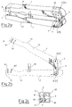
- FIGS. 1a to 1c A stripping device for conductors as well as round and flat conductors is shown in FIGS. 1a to 1c.
- FIG. 1 a it is characterized by tweezers, legs 1 and 2 lying essentially parallel, with a double joint 3 lying between them.
- the double joint 3 consists of an intermediate part 4, which is held in the upper leg 1 in a bearing 5 with a substantially cylindrical bolt element 5 'and in the lower leg 2 in a further bearing 6 with a further substantially cylindrical bolt element 6'.
- the intermediate part is square, but can also be round or oval.
- a spring 7 is embedded, which in the vicinity of the bearing 6 z. B. can be held on an inside of the lower leg 2.
- the lower leg 2 is continued at this end as a hook-shaped extension 13.
- a piston block 28 abuts an upper and one of the inner edges of the extension 13.
- the piston block 28 is also square-shaped, but can also have a different shape.
- a slot 30 is made in the piston block 28. Through this slot 30, as is also shown in FIG. 1b, the bolt 6 'of the lower bearing 6.
- the pin 29 is attached to a pin 29, a boom 27.
- the pin itself is guided in at least one slot 33, which has the shape of a lying "1".
- the boom 27 is held in the upper leg 1 by a continuous bearing 40.
- the arm 27 itself also has a square shape, although another shape is also possible.
- the square shape of the intermediate piece 4, the bracket 27 and the piston block 28 brings the advantage that on the one hand all three elements in U-shaped hollow leg sections of the legs 1 and 2 are movable without mutual hindrance and on the other hand when pressing the legs 1 and 2 mutual guidance is given.
- the respective U-shaped hollow leg section extends approximately to half the length of the leg 1 or 2.
- a pin 16 is arranged in the lower leg 2, to which a compatible groove 15 is introduced in the upper leg 1.
- a wire stripping tool 8 is arranged at the front end of both legs 1 and 2. Its cutting edge 8.1 is attached to the upper leg 1 and its other cutting edge 8.2 is attached to the lower leg 2. Both cutting edges 8.1 and 8.2 are slightly inclined forward. As is also particularly clearly shown in FIG. 3b, they are formed from the outside inwards in the form of an open triangle with opposing tips.
- a similarly shaped elongated gripper jaw 11 is arranged in front of the cutting edge 8.1, and a further gripper jaw 12 is arranged in front of the leg 8.2, the shape of which is approximately compatible with the gripper jaw 11.
- a ⁇ -shaped cutting edge 10.2 of a stripping tool for flat conductors or lines is arranged between the pin 16 and the cutting edge 8.2.
- Another cutting edge 10.1 of this tool is attached opposite to the upper leg behind the cutting edge 8.1. she is rotated by 180 ° and is thus ⁇ -shaped.
- both legs 1 and 2 are each provided with a handle elevation 31 and 32. As shown in FIG. 1 a, both grip elevations 31 and 32 lie approximately opposite one another. But they can also be arranged offset from one another. This creates additional recessed grips in front of the handle elevation 31 and behind the handle elevation 32.
- both legs 1 and 2 are shifted against each other as already described.
- the piston block 28, on which the knife part 14 is arranged and which is connected to the arm 27, is guided through the bolt element 6 'of the bearing 6 into the slot 30 of the piston block.
- a round conductor is mounted transversely to the leg axis and the knife part 14 is brought up to the jacket by loosening the handle. With a turn around the jacket, it is cut through and can then be removed.
- a flat conductor is to be stripped, it is also placed transversely to the leg axis in the tool 10 between both legs 1 and 2.
- the insulation on the flat sides of the conductor or the line is cut.
- the knife blades of the cutting edges 10.1 and 10.2 lying sideways engage in the narrow sides of the flat conductor insulation. This cutting process ensures that the specially designed cutting edges 10.1 and 10.2, combined with a movement of the two legs 1 and 2 moving from pressing against one another into one another, perform a "two-dimensional cutting movement". This enables a uniform all-round separation of these complicated conductors or wire form for stripping.
- the operator can also determine the pressure and the movement of his hand with the intermediate part 4 pressing and sliding movement or sliding and pressing movement individually and / or a smooth overlap of both movements of the legs 1 and 2, that this is optimally aimed at the object to be stripped.
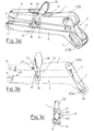
- a stripping device for conductors and round cables is shown in Figures 2a to 2c.
- this stripping device also consists of two legs 1 and 2, which are connected to one another by a double joint 3.
- a spring 7 is introduced in the intermediate part 4, which is held in the legs 1 and 2 in the bearings 5 and 6, a spring 7 is introduced. So that the upper leg 1 remains open, it strikes the intermediate part 4 with a stop 26, which can be designed to be adjustable.
- the intermediate part 4 preferably has a square shape.
- FIG. 2b and in FIG. 2c which shows the working position, it can be seen that in the front area of the legs 1 and 2 there is a wire stripping tool 8 with cutting edges 8.1 and 8.2. In front of the cutting edge 8.2 there is a triangular gripping jaw 12 projecting to the rear and in front of the cutting edge 8.1 the gripping jaw 11 with a compatible receptacle. A stripping tool 9 with its cutting edges 9.1 and 9.2 is also arranged.
- a pin 16 runs in a groove 15 provided in the lower leg 2.
- the entire stripping device must be turned through 180 ° so that, as shown in FIG. A line is now pushed into the opened tool 9.
- the handle elevations 31 and arranged on the legs 1 and 2 32 which in this case are somewhat offset from one another and the almost straight intermediate part 4 and the cutting edges 9.1 and 8.1, which are now in front of the cutting edges 9.2 and 8.2 due to the rotation by 180 °, now only allow one cutting movement of the cutting part both cutting edges 9.1 and 9.2, with which the stripping device can be professionally cut and removed when the stripping device is turned around the jacket.
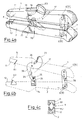
- FIGS. 3a to 3c. 3a it also consists of two opposing legs 1 and 2, which are connected to one another by a double joint 3, which consists of an intermediate part 4 rotatable in bearings 5 and 6.
- the intermediate piece 4 is longer and sloping in an pistol grip-like extension of the lower leg 2.
- a lower part 34 of a lifting joint 17 is fastened to the lower leg 2.
- a lever element 20 is attached to this joint 17 with a bolt 37.
- the lifting joint 20 hooks outwards through a groove 18 made in the leg 1 and touches with its curved surface 21 a roller cylinder 22 lying transversely in the groove 18 and inserted therein.
- the stripping device is equipped with a stripping tool 8 and gripping jaws 11 and 12.
- the cutting edges 8.1 and 8.2 of the tool 8 are designed to be larger in accordance with the cross section of the conductor to be stripped.
- a conductor is inserted into this cutting tool 8 and the gripping jaws 11 and 12, which are designed similarly to those already described. Due to the inclination of the intermediate piece 4 and the advanced upper leg 1, a greater force is already exerted on the insulation of the conductor during the cutting movement. This force is increased by pushing the lever element 20 forward with the thumb because the curved surface 21 slides on the roller cylinder 22. This surface can be curved differently, e.g. B. slightly at the beginning and rising over the middle towards the end or vice versa. By choosing the different curvature 21, the force of the lever element 17 can be guided and metered to different extents in the different movement phases.
- FIGS. 4a to 4c A further embodiment of a stripping device with a different lever element 17 is shown in FIGS. 4a to 4c.
- a double joint 3 which consists of an intermediate part 4 rotatable in bearings 5 and 6.
- the lower part 2 is also extended like a pistol grip.
- the intermediate part 4 which is brought back by a spring 7, stands almost at right angles to the lower leg 2, but also strikes a rear wall 38 serving as a return limitation.
- a lower part 34 with a cylinder bolt 24 is attached to the lower leg 2.
- the cylinder pin 24 is held by two flat or similarly shaped parts of the lower part so that the roller 24 is freely accessible from all sides.
- the lever 23 In the leg 1 there is an approximately ⁇ -shaped lever 23 which is held in the leg 1 with a bolt 36.
- the lever 23 has, as can be seen particularly from FIG. 4b, a straight line Part 39 with a tread 35. This tread 35 runs when the legs 1 and 2 are pressed together and when the lever 23 is actuated on the cylinder bolt 25.
- the legs 1 and 2 themselves are equipped with cutting edges 8.1 and 8.2 and gripper jaws 11 and 12, which have already been described in detail above.
- the force to be exerted by the actuation of the lever 23 is determined by the inclination of the straight part 39.
- the force can also be differentiated by the fact that the drainage surface 35 is not curved, as shown, but curved, e.g. B. outwards and / or inwards.
- the lever 23 is used not only for power transmission, but also for guidance purposes. Because the lever 23 is guided in the groove 18 and in the lower part 34, both legs are safely guided parallel to each other in all movements.
- the rotary sliding joint can also be designed as an elongated double joint 130.
- both legs 1, 2 are connected by an intermediate piece 140 such that the cylindrical pin element 5 ', which is arranged in the leg 1, slidably and / or rotatably in an elongated hole 141 made in the intermediate piece 140 and the second cylindrical pin element 5' in other leg 2 and is held rotatably in the intermediate piece 140.
- the intermediate piece 140 is arranged at an angle between 30 and 90 ° to one of the legs 1, 2.
- FIG. 6 A further embodiment of the rotary sliding joint in the form of an elongated hole element 230 is shown in FIG. 6.
- both legs 1, 2 are connected by an intermediate segment 240 in such a way that the cylindrical pin element 5 'which is in the leg 1 is arranged, sliding in a preferably inclined sliding recess 241 and on the other leg 2, the intermediate segment 240 is held rigidly or rotatably.
- the sliding recess 241 made in the intermediate segment 240 consists of two inclined ones Partial slots 242, 243 with different gradients.
- the cylindrical bolt element 6 'holds the intermediate segment 240 on the leg 2 rotatably and / or with a locking device 245 in a sliding or rigid manner.
- the cylindrical bolt elements 5 ', 6' here, as with the elongated double joint 130, can consist of a sliding, of two partial bolts, one or two ball bearings or one or more other rotary-sliding connecting elements .
Landscapes
- Removal Of Insulation Or Armoring From Wires Or Cables (AREA)
- Insulated Conductors (AREA)
- Surgical Instruments (AREA)
- Processing Of Terminals (AREA)
- Time-Division Multiplex Systems (AREA)
- Mobile Radio Communication Systems (AREA)
- Communication Cables (AREA)
- Defrosting Systems (AREA)
Claims (18)
- Dispositif de dénudation de conducteurs et/ou de fils électriques, se composant d'au moins deux branches (1, 2) qui forment un dispositif de dénudation,qui comportent à leur première extrémité au moins un axe de rotation (5', 6') autour duquel les branches (1, 2) peuvent pivoter pour la fermeture, etqui comportent au moins dans la zone de leurs autres extrémités au moins une partie d'outil de coupe (8.1, 8.2; 9.1, 9.2; 10.1, 10.2; 14),caractérisé en ce quel'axe de rotation est un axe de rotation double dont le premier élément de goujon (5') de forme sensiblement cylindrique est disposé dans la première branche (1) et dont le deuxième élément de goujon (6') de forme sensiblement cylindrique est agencé dans la deuxième branche (2), etles deux éléments de goujons (5', 6') sont maintenus et guidés dans un élément intermédiaire (4, 140; 240) de sorte que, sous l'effet d'une articulation à rotation et à coulissement configurée de cette manière (3; 130; 230), les deux branches (1, 2) sont maintenues en agençant comme des brucelles leurs parties (8.1, 8.2; 9.1, 9.2; 10.1, 10.2; 14) d'outils de coupe, et que ces branches peuvent lors d'un actionnement être appuyées l'une contre l'autre et coulisser dans une certaine direction l'une par rapport à l'autre avec des éléments de guidage qui y sont agencés (15, 16; 17, 18).
- Dispositif selon la revendication 1, caractérisé en ce que des outils de coupe (10.1, 10.2) d'un outil de dénudation pour conducteurs ou fils plats, outils qui sont agencés selon une configuration en L dans la direction des branches et décalés de 180° l'un par rapport à l'autre, et/ou des mâchoires de griffes (11, 12) peuvent être montés sur les côtés intérieurs des branches (1, 2) face à l'articulation à rotation et à coulissement (3; 130; 230), en plus des outils de coupe (8.1, 8.2; 9.1, 9.2) d'un outil connu (8) de dénudation de conducteur et/ou d'un outil de dénudation pour fils ronds (9).
- Dispositif selon la revendication 1 ou 2, caractérisé en ce qu'un prolongement (13) en forme de crochet, dont l'outil de coupe réalisé sous forme de partie de couteau (14) peut être éloigné ou rapproché en va-et-vient dans la direction de coulissement des deux branches (1, 2), est agencé sur l'une des branches (1).
- Dispositif selon l'une au moins des revendications 1 à 3, caractérisé en ce que l'articulation à rotation et à coulissement (3; 130; 230) est pourvue d'un élément de rappel, par exemple un ressort (7), et d'un élément de limitation (29, 33; 26; 38) de rappel qui sont agencés au moins sur l'une des branches.
- Dispositif selon l'une des au moins revendications 1 à 4, caractérisé en ce que l'articulation à rotation et à coulissement est réalisée sous forme d'une articulation double (3) dans laquelle les deux branches (1, 2) sont assemblées entre elles par un élément intermédiaire (4), qui est logé à rotation dans chacune des branches au moyen d'éléments de goujons cylindriques (5', 6').
- Dispositif selon l'une au moins des revendications 1 à 4, caractérisé en ce que l'articulation à rotation et à coulissement est réalisée sous forme d'une articulation double (130) à orifice allongé dans laquelle les deux branches (1, 2) sont assemblées par une pièce intermédiaire (140) d'une manière telle que le premier élément de goujon cylindrique (5') qui est agencé dans l'une des branches (1) est maintenu à coulissement et/ou à rotation dans un orifice allongé (140) ménagé dans la pièce intermédiaire (140), et le deuxième élément de goujon cylindrique (6') est maintenu à rotation dans l'autre branche (2) et dans la pièce intermédiaire (140).
- Dispositif selon l'une au moins des revendications 1 à 4, caractérisé en ce que l'articulation à rotation et à coulissement est réalisée sous forme d'un élément (230) à orifice allongé dans lequel les deux branches (1, 2) sont assemblées par un segment intermédiaire (240) d'une manière telle que le premier élément de goujon cylindrique (5') qui est agencé dans l'une des branches (1) est maintenu à coulissement dans un évidement de coulissement (241) disposé de préférence en oblique, et le segment intermédiaire (240) est maintenu fixe ou à rotation sur l'autre branche (2).
- Dispositif selon la revendication 7, caractériséen ce que l'évidement de coulissement (241) ménagé dans le segment intermédiaire (240) se compose de deux fentes partielles (242, 243) disposées en oblique, dont les pentes sont inégales et/ouen ce que le deuxième élément de goujon cylindrique (6') maintient l'élément intermédiaire (240) sur l'autre branche (2) à rotation et/ou à coulissement ou de façon fixe avec un dispositif de blocage (245).
- Dispositif selon l'une des revendications 1 à 8, caractérisé en ce que les éléments de goujons cylindriques (5', 6') se composent d'un goujon partiel coulissant, de deux goujons partiels, d'un ou deux roulements à billes ou d'un ou plusieurs autres éléments d'assemblage à rotation et à coulissement.
- Dispositif selon l'une au moins des revendications 1 à 9, caractérisé en ce que l'élément de guidage (16; 17) est en même temps un élément de butée pour le fil à introduire dans l'outil de dénudation (8) de conducteurs et les mâchoires de griffes (11, 12).
- Dispositif selon l'une au moins des revendications 1 à 10, caractérisé en ce que l'élément de guidage est réalisé sous forme d'au moins un tenon (16) qui coulisse dans au moins un évidement allongé (15) et qui est formé ou monté dans le côté intérieur de l'une des branches (2).
- Dispositif selon l'une au moins des revendications 1 à 11, caractérisé en ce que l'élément de guidage est réalisé sous forme d'une articulation (17) à levier qui est assemblée de façon articulée à l'une des branches (1, 2) et qui est guidée dans une encoche (18) de l'autre.
- Dispositif selon l'une au moins des revendications 1 à 12, caractérisé en ce qu'un levier (20) agencé au-dessus d'une articulation (19) de l'articulation (17) à levier comporte une surface incurvée (21) qui vient s'assembler par effet de force avec un rouleau cylindrique (22) agencé dans l'encoche (18), lors du déplacement des deux branches (1, 2) à coulissement.
- Dispositif selon l'une au moins des revendications 1 à 13, caractérisé en ce qu'un levier (23) réalisé sensiblement en forme de τ maintenu dans l'encoche (18) pénètre par effet de force, par sa partie sensiblement droite (39), au-dessous d'un goujon (25) de cylindre logé à rotation dans un oeillet (24), le levier (23) et l'oeillet (24) étant agencés dans l'une des branches (1, 2).
- Dispositif selon l'une au moins des revendications 1 à 12, caractérisé en ce que l'élément intermédiaire (4) et la pièce intermédiaire (140) sont agencés selon un angle compris entre 30 et 90° par rapport à l'une des branches (1, 2).
- Dispositif selon l'une au moins des revendications 1 à 15, caractérisé en ce que l'élément de limitation de rappel est en forme de goujon cylindrique (29) qui se déplace dans des évidements (33) en forme de fentes ménagés dans l'une des branches (1, 2) et est maintenu par une console (27) qui est agencée au voisinage de l'un des points de palier (5, 6), en forme de paroi arrière fixe (38) dans l'un des points de palier (5, 6) des branches et/ou en forme de butée réglable (26) agencée dans l'une des branches (1, 2).
- Dispositif selon l'une au moins des revendications 1 à 16, caractérisé en ce que la partie de couteau (14) est agencée sur un bloc (28) de piston qui est assemblé à une console (27) et qui est guidé par une tige (6') de l'un des paliers (6) dans une fente (30) du bloc (28) de piston.
- Dispositif selon l'une au moins des revendications 1 à 17, caractérisé en ce qu'au moins l'une des branches (1, 2) présente sur son côté extérieur une surélévation (31, 32) de saisie, qui sont situées face à face ou décalées l'une par rapport à l'autre.
Applications Claiming Priority (3)
| Application Number | Priority Date | Filing Date | Title |
|---|---|---|---|
| DE4221500 | 1992-07-02 | ||
| DE4221500A DE4221500C1 (de) | 1992-07-02 | 1992-07-02 | Vorrichtung zur Abisolierung elektrischer Leiter und/oder Leitungen |
| PCT/EP1993/001695 WO1994001906A1 (fr) | 1992-07-02 | 1993-07-01 | Dispositif servant a denuder des conducteurs et/ou des fils electriques |
Publications (2)
| Publication Number | Publication Date |
|---|---|
| EP0606438A1 EP0606438A1 (fr) | 1994-07-20 |
| EP0606438B1 true EP0606438B1 (fr) | 1997-12-10 |
Family
ID=6462186
Family Applications (1)
| Application Number | Title | Priority Date | Filing Date |
|---|---|---|---|
| EP93915760A Expired - Lifetime EP0606438B1 (fr) | 1992-07-02 | 1993-07-01 | Dispositif servant a denuder des conducteurs et/ou des fils electriques |
Country Status (11)
| Country | Link |
|---|---|
| US (1) | US5469762A (fr) |
| EP (1) | EP0606438B1 (fr) |
| JP (1) | JPH07501440A (fr) |
| AT (1) | ATE161122T1 (fr) |
| AU (1) | AU671471B2 (fr) |
| CA (1) | CA2116847A1 (fr) |
| DE (2) | DE4221500C1 (fr) |
| DK (1) | DK0606438T3 (fr) |
| ES (1) | ES2110618T3 (fr) |
| FI (1) | FI940989L (fr) |
| WO (1) | WO1994001906A1 (fr) |
Cited By (1)
| Publication number | Priority date | Publication date | Assignee | Title |
|---|---|---|---|---|
| DE102006041842A1 (de) * | 2006-09-06 | 2008-03-27 | Schäfer Werkzeug- und Sondermaschinenbau GmbH | Verfahren und Vorrichtung zum Einfügen eines Kabelendes in eine Kabeltülle |
Families Citing this family (10)
| Publication number | Priority date | Publication date | Assignee | Title |
|---|---|---|---|---|
| US5604768A (en) * | 1992-01-09 | 1997-02-18 | Cellnet Data Systems, Inc. | Frequency synchronized bidirectional radio system |
| USD375884S (en) | 1995-08-21 | 1996-11-26 | Palmer Kenneth S | Clipper for small diameter plastic rod |
| DE19607949C1 (de) * | 1996-03-01 | 1997-04-17 | Franz Krampe | Abisoliervorrichtung |
| USD415940S (en) | 1998-09-29 | 1999-11-02 | Elmont E Hollingsworth | Wire and cable stripper |
| DE20004643U1 (de) | 2000-03-13 | 2000-08-10 | Krampe, Franz, 59387 Ascheberg | Abisolierzange |
| US6739229B2 (en) | 2002-06-19 | 2004-05-25 | Thomas D. Scollon | Cable stripping device |
| US20130175425A1 (en) * | 2011-10-26 | 2013-07-11 | Martin James Burger | Rotor retrieval tool |
| WO2016004438A1 (fr) * | 2014-07-03 | 2016-01-07 | Ppc Broadband, Inc. | Cartouche à lame modulaire pour outil de dénudage de câble et outil de dénudage utilisant une cartouche à lame modulaire |
| JP2016030284A (ja) * | 2014-07-29 | 2016-03-07 | トヨタ自動車株式会社 | 平角線の切断方法、及び切断刃具 |
| DE202017107094U1 (de) * | 2017-11-23 | 2018-01-02 | Weicon Gmbh & Co Kg | Coaxialkabel-Abisolierwerkzeug |
Family Cites Families (11)
| Publication number | Priority date | Publication date | Assignee | Title |
|---|---|---|---|---|
| GB792055A (en) * | 1955-05-06 | 1958-03-19 | Douglas Peter Davidson | Wire stripping tool |
| US3125908A (en) * | 1961-05-13 | 1964-03-24 | rozmus | |
| US4094214A (en) * | 1975-07-18 | 1978-06-13 | Farinon Electric | Wire insulation stripping device |
| AU533375B2 (en) * | 1979-10-09 | 1983-11-17 | Mcc Corp. | Insulation stripping tool |
| DE8015173U1 (de) * | 1980-06-07 | 1980-09-04 | C. A. Weidmueller Kg, 4930 Detmold | Abstreifbacke für Abisolierzangen |
| DE3241530A1 (de) * | 1982-11-10 | 1984-05-10 | Josef 4715 Ascheberg Krampe | Abisolierzange |
| DE3331979A1 (de) * | 1983-09-05 | 1985-04-04 | Franz 4715 Ascheberg Krampe | Abisoliergeraet fuer kabelenden |
| DD248003A1 (de) * | 1986-04-09 | 1987-07-22 | Werkzeugind Forschzent | Werkzeug zum abisolieren elektrischer leiter |
| DE3632685A1 (de) * | 1986-09-26 | 1988-03-31 | Scheiter & Krampe | Werkzeug zur bearbeitung von kabelenden |
| DE3922016A1 (de) * | 1989-03-04 | 1990-09-13 | Krampe Franz | Abisolierzange |
| US4951393A (en) * | 1989-07-18 | 1990-08-28 | Wallace Archie C | Wire stripper |
-
1992
- 1992-07-02 DE DE4221500A patent/DE4221500C1/de not_active Expired - Fee Related
-
1993
- 1993-07-01 WO PCT/EP1993/001695 patent/WO1994001906A1/fr not_active Ceased
- 1993-07-01 JP JP6502910A patent/JPH07501440A/ja not_active Expired - Lifetime
- 1993-07-01 FI FI940989A patent/FI940989L/fi unknown
- 1993-07-01 DE DE59307818T patent/DE59307818D1/de not_active Expired - Fee Related
- 1993-07-01 EP EP93915760A patent/EP0606438B1/fr not_active Expired - Lifetime
- 1993-07-01 CA CA002116847A patent/CA2116847A1/fr not_active Abandoned
- 1993-07-01 US US08/204,158 patent/US5469762A/en not_active Expired - Fee Related
- 1993-07-01 DK DK93915760T patent/DK0606438T3/da active
- 1993-07-01 AU AU45624/93A patent/AU671471B2/en not_active Ceased
- 1993-07-01 ES ES93915760T patent/ES2110618T3/es not_active Expired - Lifetime
- 1993-07-01 AT AT93915760T patent/ATE161122T1/de not_active IP Right Cessation
Cited By (1)
| Publication number | Priority date | Publication date | Assignee | Title |
|---|---|---|---|---|
| DE102006041842A1 (de) * | 2006-09-06 | 2008-03-27 | Schäfer Werkzeug- und Sondermaschinenbau GmbH | Verfahren und Vorrichtung zum Einfügen eines Kabelendes in eine Kabeltülle |
Also Published As
| Publication number | Publication date |
|---|---|
| US5469762A (en) | 1995-11-28 |
| JPH07501440A (ja) | 1995-02-09 |
| FI940989A7 (fi) | 1994-04-12 |
| AU4562493A (en) | 1994-01-31 |
| AU671471B2 (en) | 1996-08-29 |
| DK0606438T3 (da) | 1998-08-24 |
| DE4221500C1 (de) | 1993-09-30 |
| CA2116847A1 (fr) | 1994-01-20 |
| DE59307818D1 (de) | 1998-01-22 |
| WO1994001906A1 (fr) | 1994-01-20 |
| ATE161122T1 (de) | 1997-12-15 |
| FI940989L (fi) | 1994-04-12 |
| EP0606438A1 (fr) | 1994-07-20 |
| FI940989A0 (fi) | 1994-03-02 |
| ES2110618T3 (es) | 1998-02-16 |
Similar Documents
| Publication | Publication Date | Title |
|---|---|---|
| DE2402187C3 (de) | Handzange zum Abisolieren von Leiterenden | |
| EP2056415B1 (fr) | Pince à dénuder | |
| EP0309871B1 (fr) | Pince à main pour dénuder les extrémités de conducteurs | |
| DE3241530A1 (de) | Abisolierzange | |
| EP2056416A2 (fr) | Pince à dénuder | |
| DE3030610C2 (de) | Zangenartiges Werkzeug zum Abisolieren der isolierenden Umhüllung von elektrisch isolierten Leitern | |
| WO2005071811A1 (fr) | Pince a denuder qui s'adapte automatiquement a differentes sections transversales de conducteur | |
| WO1994001906A1 (fr) | Dispositif servant a denuder des conducteurs et/ou des fils electriques | |
| DE19607949C1 (de) | Abisoliervorrichtung | |
| DE19842122A1 (de) | Zangenartig zu handhabendes Werkzeug | |
| DE3781614T2 (de) | Kabelabmantelungswerkzeug. | |
| DE4420006C2 (de) | Zange zum Abisolieren von Leiterenden | |
| EP1671407B1 (fr) | Pince a denuder automatique | |
| DE3922016C2 (fr) | ||
| DE3632685C2 (fr) | ||
| DE2930612A1 (de) | Verfahren und vorrichtung zum abisolieren von elektrischen leitern bzw. abmanteln von elektrischen kabeln | |
| EP4200946A2 (fr) | Pince manuelle conçue pour réaliser un sertissage et pince manuelle pourvue d'une tête de pince | |
| DE2200516A1 (de) | Draht-Abstreifzange | |
| DE10209181B4 (de) | Verfahren und Zange zum Abisolieren von Leiterenden | |
| EP0516960B1 (fr) | Dispositif pour séparer un câble porteur | |
| EP4002614A1 (fr) | Pince à dénuder | |
| DE10110869C2 (de) | Abisolierzange | |
| DE2414739C2 (de) | Zangenartiges Werkzeug zum Abtrennen und Abziehen der Isolierung von den Enden isolierter Leiter | |
| DE2120854C (de) | Vorrichtung zum Zerschneiden und Abisolieren eines Schaltdrahtes | |
| DE202007017936U1 (de) | Abisolierzange |
Legal Events
| Date | Code | Title | Description |
|---|---|---|---|
| PUAI | Public reference made under article 153(3) epc to a published international application that has entered the european phase |
Free format text: ORIGINAL CODE: 0009012 |
|
| AK | Designated contracting states |
Kind code of ref document: A1 Designated state(s): AT BE CH DE DK ES FR GB GR IE IT LI LU MC NL PT SE |
|
| 17P | Request for examination filed |
Effective date: 19940622 |
|
| GRAG | Despatch of communication of intention to grant |
Free format text: ORIGINAL CODE: EPIDOS AGRA |
|
| 17Q | First examination report despatched |
Effective date: 19970320 |
|
| GRAG | Despatch of communication of intention to grant |
Free format text: ORIGINAL CODE: EPIDOS AGRA |
|
| GRAH | Despatch of communication of intention to grant a patent |
Free format text: ORIGINAL CODE: EPIDOS IGRA |
|
| GRAH | Despatch of communication of intention to grant a patent |
Free format text: ORIGINAL CODE: EPIDOS IGRA |
|
| GRAA | (expected) grant |
Free format text: ORIGINAL CODE: 0009210 |
|
| AK | Designated contracting states |
Kind code of ref document: B1 Designated state(s): AT BE CH DE DK ES FR GB GR IE IT LI LU MC NL PT SE |
|
| PG25 | Lapsed in a contracting state [announced via postgrant information from national office to epo] |
Ref country code: GR Free format text: LAPSE BECAUSE OF FAILURE TO SUBMIT A TRANSLATION OF THE DESCRIPTION OR TO PAY THE FEE WITHIN THE PRESCRIBED TIME-LIMIT Effective date: 19971210 |
|
| REF | Corresponds to: |
Ref document number: 161122 Country of ref document: AT Date of ref document: 19971215 Kind code of ref document: T |
|
| REG | Reference to a national code |
Ref country code: CH Ref legal event code: EP |
|
| GBT | Gb: translation of ep patent filed (gb section 77(6)(a)/1977) |
Effective date: 19971211 |
|
| REG | Reference to a national code |
Ref country code: CH Ref legal event code: NV Representative=s name: PATMED AG |
|
| REF | Corresponds to: |
Ref document number: 59307818 Country of ref document: DE Date of ref document: 19980122 |
|
| ITF | It: translation for a ep patent filed | ||
| REG | Reference to a national code |
Ref country code: ES Ref legal event code: FG2A Ref document number: 2110618 Country of ref document: ES Kind code of ref document: T3 |
|
| PG25 | Lapsed in a contracting state [announced via postgrant information from national office to epo] |
Ref country code: PT Free format text: LAPSE BECAUSE OF FAILURE TO SUBMIT A TRANSLATION OF THE DESCRIPTION OR TO PAY THE FEE WITHIN THE PRESCRIBED TIME-LIMIT Effective date: 19980310 |
|
| ET | Fr: translation filed | ||
| REG | Reference to a national code |
Ref country code: IE Ref legal event code: FG4D Free format text: 77799 |
|
| PGFP | Annual fee paid to national office [announced via postgrant information from national office to epo] |
Ref country code: GB Payment date: 19980612 Year of fee payment: 6 |
|
| PGFP | Annual fee paid to national office [announced via postgrant information from national office to epo] |
Ref country code: LU Payment date: 19980625 Year of fee payment: 6 Ref country code: DK Payment date: 19980625 Year of fee payment: 6 |
|
| PGFP | Annual fee paid to national office [announced via postgrant information from national office to epo] |
Ref country code: CH Payment date: 19980701 Year of fee payment: 6 |
|
| PG25 | Lapsed in a contracting state [announced via postgrant information from national office to epo] |
Ref country code: IE Free format text: LAPSE BECAUSE OF NON-PAYMENT OF DUE FEES Effective date: 19980714 |
|
| REG | Reference to a national code |
Ref country code: IE Ref legal event code: FD4D Ref document number: 77799 Country of ref document: IE |
|
| REG | Reference to a national code |
Ref country code: DK Ref legal event code: T3 |
|
| PLBE | No opposition filed within time limit |
Free format text: ORIGINAL CODE: 0009261 |
|
| STAA | Information on the status of an ep patent application or granted ep patent |
Free format text: STATUS: NO OPPOSITION FILED WITHIN TIME LIMIT |
|
| 26N | No opposition filed | ||
| PG25 | Lapsed in a contracting state [announced via postgrant information from national office to epo] |
Ref country code: MC Free format text: LAPSE BECAUSE OF NON-PAYMENT OF DUE FEES Effective date: 19990131 |
|
| PGFP | Annual fee paid to national office [announced via postgrant information from national office to epo] |
Ref country code: SE Payment date: 19990628 Year of fee payment: 7 Ref country code: FR Payment date: 19990628 Year of fee payment: 7 |
|
| PGFP | Annual fee paid to national office [announced via postgrant information from national office to epo] |
Ref country code: NL Payment date: 19990630 Year of fee payment: 7 Ref country code: AT Payment date: 19990630 Year of fee payment: 7 |
|
| PG25 | Lapsed in a contracting state [announced via postgrant information from national office to epo] |
Ref country code: LU Free format text: LAPSE BECAUSE OF NON-PAYMENT OF DUE FEES Effective date: 19990701 Ref country code: GB Free format text: LAPSE BECAUSE OF NON-PAYMENT OF DUE FEES Effective date: 19990701 |
|
| PGFP | Annual fee paid to national office [announced via postgrant information from national office to epo] |
Ref country code: BE Payment date: 19990706 Year of fee payment: 7 |
|
| PGFP | Annual fee paid to national office [announced via postgrant information from national office to epo] |
Ref country code: ES Payment date: 19990720 Year of fee payment: 7 |
|
| PG25 | Lapsed in a contracting state [announced via postgrant information from national office to epo] |
Ref country code: LI Free format text: LAPSE BECAUSE OF NON-PAYMENT OF DUE FEES Effective date: 19990731 Ref country code: CH Free format text: LAPSE BECAUSE OF NON-PAYMENT OF DUE FEES Effective date: 19990731 |
|
| PG25 | Lapsed in a contracting state [announced via postgrant information from national office to epo] |
Ref country code: DK Free format text: LAPSE BECAUSE OF NON-PAYMENT OF DUE FEES Effective date: 19990802 |
|
| GBPC | Gb: european patent ceased through non-payment of renewal fee |
Effective date: 19990701 |
|
| REG | Reference to a national code |
Ref country code: CH Ref legal event code: PL |
|
| REG | Reference to a national code |
Ref country code: DK Ref legal event code: EBP |
|
| PG25 | Lapsed in a contracting state [announced via postgrant information from national office to epo] |
Ref country code: AT Free format text: LAPSE BECAUSE OF NON-PAYMENT OF DUE FEES Effective date: 20000701 |
|
| PG25 | Lapsed in a contracting state [announced via postgrant information from national office to epo] |
Ref country code: SE Free format text: LAPSE BECAUSE OF NON-PAYMENT OF DUE FEES Effective date: 20000702 Ref country code: ES Free format text: LAPSE BECAUSE OF NON-PAYMENT OF DUE FEES Effective date: 20000702 |
|
| PG25 | Lapsed in a contracting state [announced via postgrant information from national office to epo] |
Ref country code: BE Free format text: LAPSE BECAUSE OF NON-PAYMENT OF DUE FEES Effective date: 20000731 |
|
| BERE | Be: lapsed |
Owner name: KRAMPE FRANZ Effective date: 20000731 |
|
| PG25 | Lapsed in a contracting state [announced via postgrant information from national office to epo] |
Ref country code: NL Free format text: LAPSE BECAUSE OF NON-PAYMENT OF DUE FEES Effective date: 20010201 |
|
| EUG | Se: european patent has lapsed |
Ref document number: 93915760.8 |
|
| PG25 | Lapsed in a contracting state [announced via postgrant information from national office to epo] |
Ref country code: FR Free format text: LAPSE BECAUSE OF NON-PAYMENT OF DUE FEES Effective date: 20010330 |
|
| NLV4 | Nl: lapsed or anulled due to non-payment of the annual fee |
Effective date: 20010201 |
|
| REG | Reference to a national code |
Ref country code: FR Ref legal event code: ST |
|
| REG | Reference to a national code |
Ref country code: ES Ref legal event code: FD2A Effective date: 20010810 |
|
| PG25 | Lapsed in a contracting state [announced via postgrant information from national office to epo] |
Ref country code: IT Free format text: LAPSE BECAUSE OF NON-PAYMENT OF DUE FEES;WARNING: LAPSES OF ITALIAN PATENTS WITH EFFECTIVE DATE BEFORE 2007 MAY HAVE OCCURRED AT ANY TIME BEFORE 2007. THE CORRECT EFFECTIVE DATE MAY BE DIFFERENT FROM THE ONE RECORDED. Effective date: 20050701 |
|
| PGFP | Annual fee paid to national office [announced via postgrant information from national office to epo] |
Ref country code: DE Payment date: 20050909 Year of fee payment: 13 |
|
| PG25 | Lapsed in a contracting state [announced via postgrant information from national office to epo] |
Ref country code: DE Free format text: LAPSE BECAUSE OF NON-PAYMENT OF DUE FEES Effective date: 20070201 |