EP0606499A1 - Dispositif et procede d'enregistrement sur disque - Google Patents
Dispositif et procede d'enregistrement sur disque Download PDFInfo
- Publication number
- EP0606499A1 EP0606499A1 EP93916244A EP93916244A EP0606499A1 EP 0606499 A1 EP0606499 A1 EP 0606499A1 EP 93916244 A EP93916244 A EP 93916244A EP 93916244 A EP93916244 A EP 93916244A EP 0606499 A1 EP0606499 A1 EP 0606499A1
- Authority
- EP
- European Patent Office
- Prior art keywords
- cluster
- recording
- disc
- data
- defective
- Prior art date
- Legal status (The legal status is an assumption and is not a legal conclusion. Google has not performed a legal analysis and makes no representation as to the accuracy of the status listed.)
- Granted
Links
Images



Classifications
-
- G—PHYSICS
- G11—INFORMATION STORAGE
- G11B—INFORMATION STORAGE BASED ON RELATIVE MOVEMENT BETWEEN RECORD CARRIER AND TRANSDUCER
- G11B20/00—Signal processing not specific to the method of recording or reproducing; Circuits therefor
- G11B20/10—Digital recording or reproducing
- G11B20/18—Error detection or correction; Testing, e.g. of drop-outs
- G11B20/1883—Methods for assignment of alternate areas for defective areas
-
- G—PHYSICS
- G11—INFORMATION STORAGE
- G11B—INFORMATION STORAGE BASED ON RELATIVE MOVEMENT BETWEEN RECORD CARRIER AND TRANSDUCER
- G11B11/00—Recording on or reproducing from the same record carrier wherein for these two operations the methods are covered by different main groups of groups G11B3/00 - G11B7/00 or by different subgroups of group G11B9/00; Record carriers therefor
- G11B11/10—Recording on or reproducing from the same record carrier wherein for these two operations the methods are covered by different main groups of groups G11B3/00 - G11B7/00 or by different subgroups of group G11B9/00; Record carriers therefor using recording by magnetic means or other means for magnetisation or demagnetisation of a record carrier, e.g. light induced spin magnetisation; Demagnetisation by thermal or stress means in the presence or not of an orienting magnetic field
- G11B11/105—Recording on or reproducing from the same record carrier wherein for these two operations the methods are covered by different main groups of groups G11B3/00 - G11B7/00 or by different subgroups of group G11B9/00; Record carriers therefor using recording by magnetic means or other means for magnetisation or demagnetisation of a record carrier, e.g. light induced spin magnetisation; Demagnetisation by thermal or stress means in the presence or not of an orienting magnetic field using a beam of light or a magnetic field for recording by change of magnetisation and a beam of light for reproducing, i.e. magneto-optical, e.g. light-induced thermomagnetic recording, spin magnetisation recording, Kerr or Faraday effect reproducing
- G11B11/10502—Recording on or reproducing from the same record carrier wherein for these two operations the methods are covered by different main groups of groups G11B3/00 - G11B7/00 or by different subgroups of group G11B9/00; Record carriers therefor using recording by magnetic means or other means for magnetisation or demagnetisation of a record carrier, e.g. light induced spin magnetisation; Demagnetisation by thermal or stress means in the presence or not of an orienting magnetic field using a beam of light or a magnetic field for recording by change of magnetisation and a beam of light for reproducing, i.e. magneto-optical, e.g. light-induced thermomagnetic recording, spin magnetisation recording, Kerr or Faraday effect reproducing characterised by the transducing operation to be executed
- G11B11/10504—Recording
-
- G—PHYSICS
- G11—INFORMATION STORAGE
- G11B—INFORMATION STORAGE BASED ON RELATIVE MOVEMENT BETWEEN RECORD CARRIER AND TRANSDUCER
- G11B11/00—Recording on or reproducing from the same record carrier wherein for these two operations the methods are covered by different main groups of groups G11B3/00 - G11B7/00 or by different subgroups of group G11B9/00; Record carriers therefor
- G11B11/10—Recording on or reproducing from the same record carrier wherein for these two operations the methods are covered by different main groups of groups G11B3/00 - G11B7/00 or by different subgroups of group G11B9/00; Record carriers therefor using recording by magnetic means or other means for magnetisation or demagnetisation of a record carrier, e.g. light induced spin magnetisation; Demagnetisation by thermal or stress means in the presence or not of an orienting magnetic field
- G11B11/105—Recording on or reproducing from the same record carrier wherein for these two operations the methods are covered by different main groups of groups G11B3/00 - G11B7/00 or by different subgroups of group G11B9/00; Record carriers therefor using recording by magnetic means or other means for magnetisation or demagnetisation of a record carrier, e.g. light induced spin magnetisation; Demagnetisation by thermal or stress means in the presence or not of an orienting magnetic field using a beam of light or a magnetic field for recording by change of magnetisation and a beam of light for reproducing, i.e. magneto-optical, e.g. light-induced thermomagnetic recording, spin magnetisation recording, Kerr or Faraday effect reproducing
- G11B11/10595—Control of operating function
-
- G—PHYSICS
- G11—INFORMATION STORAGE
- G11B—INFORMATION STORAGE BASED ON RELATIVE MOVEMENT BETWEEN RECORD CARRIER AND TRANSDUCER
- G11B20/00—Signal processing not specific to the method of recording or reproducing; Circuits therefor
- G11B20/10—Digital recording or reproducing
- G11B20/12—Formatting, e.g. arrangement of data block or words on the record carriers
- G11B20/1217—Formatting, e.g. arrangement of data block or words on the record carriers on discs
-
- G—PHYSICS
- G11—INFORMATION STORAGE
- G11B—INFORMATION STORAGE BASED ON RELATIVE MOVEMENT BETWEEN RECORD CARRIER AND TRANSDUCER
- G11B27/00—Editing; Indexing; Addressing; Timing or synchronising; Monitoring; Measuring tape travel
- G11B27/02—Editing, e.g. varying the order of information signals recorded on, or reproduced from, record carriers
- G11B27/031—Electronic editing of digitised analogue information signals, e.g. audio or video signals
- G11B27/034—Electronic editing of digitised analogue information signals, e.g. audio or video signals on discs
-
- G—PHYSICS
- G11—INFORMATION STORAGE
- G11B—INFORMATION STORAGE BASED ON RELATIVE MOVEMENT BETWEEN RECORD CARRIER AND TRANSDUCER
- G11B27/00—Editing; Indexing; Addressing; Timing or synchronising; Monitoring; Measuring tape travel
- G11B27/10—Indexing; Addressing; Timing or synchronising; Measuring tape travel
- G11B27/11—Indexing; Addressing; Timing or synchronising; Measuring tape travel by using information not detectable on the record carrier
-
- G—PHYSICS
- G11—INFORMATION STORAGE
- G11B—INFORMATION STORAGE BASED ON RELATIVE MOVEMENT BETWEEN RECORD CARRIER AND TRANSDUCER
- G11B27/00—Editing; Indexing; Addressing; Timing or synchronising; Monitoring; Measuring tape travel
- G11B27/10—Indexing; Addressing; Timing or synchronising; Measuring tape travel
- G11B27/19—Indexing; Addressing; Timing or synchronising; Measuring tape travel by using information detectable on the record carrier
- G11B27/28—Indexing; Addressing; Timing or synchronising; Measuring tape travel by using information detectable on the record carrier by using information signals recorded by the same method as the main recording
- G11B27/32—Indexing; Addressing; Timing or synchronising; Measuring tape travel by using information detectable on the record carrier by using information signals recorded by the same method as the main recording on separate auxiliary tracks of the same or an auxiliary record carrier
- G11B27/327—Table of contents
- G11B27/329—Table of contents on a disc [VTOC]
-
- G—PHYSICS
- G11—INFORMATION STORAGE
- G11B—INFORMATION STORAGE BASED ON RELATIVE MOVEMENT BETWEEN RECORD CARRIER AND TRANSDUCER
- G11B7/00—Recording or reproducing by optical means, e.g. recording using a thermal beam of optical radiation by modifying optical properties or the physical structure, reproducing using an optical beam at lower power by sensing optical properties; Record carriers therefor
- G11B7/002—Recording, reproducing or erasing systems characterised by the shape or form of the carrier
- G11B7/0037—Recording, reproducing or erasing systems characterised by the shape or form of the carrier with discs
- G11B7/00375—Recording, reproducing or erasing systems characterised by the shape or form of the carrier with discs arrangements for detection of physical defects, e.g. of recording layer
-
- G—PHYSICS
- G11—INFORMATION STORAGE
- G11B—INFORMATION STORAGE BASED ON RELATIVE MOVEMENT BETWEEN RECORD CARRIER AND TRANSDUCER
- G11B7/00—Recording or reproducing by optical means, e.g. recording using a thermal beam of optical radiation by modifying optical properties or the physical structure, reproducing using an optical beam at lower power by sensing optical properties; Record carriers therefor
- G11B7/004—Recording, reproducing or erasing methods; Read, write or erase circuits therefor
- G11B7/0045—Recording
-
- G—PHYSICS
- G11—INFORMATION STORAGE
- G11B—INFORMATION STORAGE BASED ON RELATIVE MOVEMENT BETWEEN RECORD CARRIER AND TRANSDUCER
- G11B20/00—Signal processing not specific to the method of recording or reproducing; Circuits therefor
- G11B20/10—Digital recording or reproducing
- G11B20/12—Formatting, e.g. arrangement of data block or words on the record carriers
- G11B20/1217—Formatting, e.g. arrangement of data block or words on the record carriers on discs
- G11B2020/1218—Formatting, e.g. arrangement of data block or words on the record carriers on discs wherein the formatting concerns a specific area of the disc
- G11B2020/1221—Formatting, e.g. arrangement of data block or words on the record carriers on discs wherein the formatting concerns a specific area of the disc cluster, i.e. a data structure which consists of a fixed number of sectors or ECC blocks
-
- G—PHYSICS
- G11—INFORMATION STORAGE
- G11B—INFORMATION STORAGE BASED ON RELATIVE MOVEMENT BETWEEN RECORD CARRIER AND TRANSDUCER
- G11B2220/00—Record carriers by type
- G11B2220/20—Disc-shaped record carriers
-
- G—PHYSICS
- G11—INFORMATION STORAGE
- G11B—INFORMATION STORAGE BASED ON RELATIVE MOVEMENT BETWEEN RECORD CARRIER AND TRANSDUCER
- G11B2220/00—Record carriers by type
- G11B2220/20—Disc-shaped record carriers
- G11B2220/25—Disc-shaped record carriers characterised in that the disc is based on a specific recording technology
- G11B2220/2525—Magneto-optical [MO] discs
- G11B2220/2529—Mini-discs
-
- G—PHYSICS
- G11—INFORMATION STORAGE
- G11B—INFORMATION STORAGE BASED ON RELATIVE MOVEMENT BETWEEN RECORD CARRIER AND TRANSDUCER
- G11B2220/00—Record carriers by type
- G11B2220/20—Disc-shaped record carriers
- G11B2220/25—Disc-shaped record carriers characterised in that the disc is based on a specific recording technology
- G11B2220/2537—Optical discs
- G11B2220/2545—CDs
-
- G—PHYSICS
- G11—INFORMATION STORAGE
- G11B—INFORMATION STORAGE BASED ON RELATIVE MOVEMENT BETWEEN RECORD CARRIER AND TRANSDUCER
- G11B2220/00—Record carriers by type
- G11B2220/60—Solid state media
- G11B2220/65—Solid state media wherein solid state memory is used for storing indexing information or metadata
-
- G—PHYSICS
- G11—INFORMATION STORAGE
- G11B—INFORMATION STORAGE BASED ON RELATIVE MOVEMENT BETWEEN RECORD CARRIER AND TRANSDUCER
- G11B2220/00—Record carriers by type
- G11B2220/90—Tape-like record carriers
- G11B2220/91—Helical scan format, wherein tracks are slightly tilted with respect to tape direction, e.g. VHS, DAT, DVC, AIT or exabyte
- G11B2220/913—Digital audio tape [DAT] format
-
- G—PHYSICS
- G11—INFORMATION STORAGE
- G11B—INFORMATION STORAGE BASED ON RELATIVE MOVEMENT BETWEEN RECORD CARRIER AND TRANSDUCER
- G11B27/00—Editing; Indexing; Addressing; Timing or synchronising; Monitoring; Measuring tape travel
- G11B27/10—Indexing; Addressing; Timing or synchronising; Measuring tape travel
- G11B27/19—Indexing; Addressing; Timing or synchronising; Measuring tape travel by using information detectable on the record carrier
- G11B27/28—Indexing; Addressing; Timing or synchronising; Measuring tape travel by using information detectable on the record carrier by using information signals recorded by the same method as the main recording
- G11B27/30—Indexing; Addressing; Timing or synchronising; Measuring tape travel by using information detectable on the record carrier by using information signals recorded by the same method as the main recording on the same track as the main recording
- G11B27/3027—Indexing; Addressing; Timing or synchronising; Measuring tape travel by using information detectable on the record carrier by using information signals recorded by the same method as the main recording on the same track as the main recording used signal is digitally coded
-
- G—PHYSICS
- G11—INFORMATION STORAGE
- G11B—INFORMATION STORAGE BASED ON RELATIVE MOVEMENT BETWEEN RECORD CARRIER AND TRANSDUCER
- G11B27/00—Editing; Indexing; Addressing; Timing or synchronising; Monitoring; Measuring tape travel
- G11B27/36—Monitoring, i.e. supervising the progress of recording or reproducing
-
- G—PHYSICS
- G11—INFORMATION STORAGE
- G11B—INFORMATION STORAGE BASED ON RELATIVE MOVEMENT BETWEEN RECORD CARRIER AND TRANSDUCER
- G11B7/00—Recording or reproducing by optical means, e.g. recording using a thermal beam of optical radiation by modifying optical properties or the physical structure, reproducing using an optical beam at lower power by sensing optical properties; Record carriers therefor
- G11B7/08—Disposition or mounting of heads or light sources relatively to record carriers
- G11B7/09—Disposition or mounting of heads or light sources relatively to record carriers with provision for moving the light beam or focus plane for the purpose of maintaining alignment of the light beam relative to the record carrier during transducing operation, e.g. to compensate for surface irregularities of the latter or for track following
- G11B7/0948—Disposition or mounting of heads or light sources relatively to record carriers with provision for moving the light beam or focus plane for the purpose of maintaining alignment of the light beam relative to the record carrier during transducing operation, e.g. to compensate for surface irregularities of the latter or for track following specially adapted for detection and avoidance or compensation of imperfections on the carrier, e.g. dust, scratches, dropouts
Definitions
- the present invention relates to a disc recording apparatus for recording a data on a disc such as a magneto-optical disc, an optical disc or the like and a recording method thereof.
- a disc such as the magneto-optical disc, the optical disc or the like sometimes has a defective portion at a predetermined portion of a track in which a data is recorded. In such case, even if the data is recorded at the defective portion, then an accurate reproduction thereof is difficult. If an audio signal, for example, is recorded, there is then such a fear that when the defective portion is reproduced, a reproduced sound breaks off and a noise is reproduced.
- the defective portion of the track is a very short section, then an original recorded data can be restored by an error correction and an interpolation processing of a reproduced data or the like, while if the defective portion is continued for a certain long section, then such restoration processing is difficult.
- the present invention is made in view of such problems, and an object thereof is to provide a disc recording apparatus and a disc recording method in which a data can be recorded so that the data can be continuously reproduced even if a predetermined section of the track formed on a disc is a defective section.
- a recording apparatus for recording a predetermined data on a disc in which clusters which are divided at a predetermined section are formed on a track
- a memory means for once storing a data
- a discriminating means for discriminating whether or not the above-mentioned cluster is a defective section
- a controlling means for performing such control that if the above-mentioned discriminating means discriminates that the cluster under recording is defective, then the recording is once stopped and such control that a cluster offset by a predetermined cluster is calculated from the above-mentioned defective cluster and a data is read again from the above-mentioned memory means to begin the recording again from the above-mentioned calculated cluster. Therefore, if a cluster having a defective section is detected in a track formed on a disc, then the cluster having the defect is avoided and the data is accurately recorded without lack thereof, so that the recorded data can be accurately reproduced upon reproduction.
- a program recorded by the above-mentioned recording apparatus is formed of one or a plurality of parts.
- the above-mentioned disc has a managing information area in which a managing information formed of at least a start address, an end address and a link information corresponding to each of the above-mentioned parts is recorded.
- the cluster under recording is determined as a defective one, then control is performed in such a manner that an end of a cluster preceding the above-mentioned cluster determined as the defective one is defined as an end address and registered as the first part in the above-mentioned managing information area and the cluster offset by a predetermined cluster is calculated from the above-mentioned cluster determined as the defective one, a start end of the above-mentioned calculated cluster is defined as an start address and registered as the second part in the above-mentioned managing information area, and a link information of the first part indicates the above-mentioned second part. Therefore, by a recorded information in the managing information area of the disc, the cluster having the defective section is avoided and it can be easily controlled to continuously reproduce the recorded data.
- a defective area of the above-mentioned disc is formed of one or a plurality of parts.
- the above-mentioned disc has the managing information area in which the managing information formed of at least the start address, the end address and the link information corresponding to each of the above-mentioned parts is recorded. If the cluster under recording is determined as the defective one, then control is performed in such a manner that the start end and the end of the above-mentioned cluster determined as the defective one are respectively defined as the start address and the end address and recorded in the above-mentioned managing information area. Therefore, the data can be reproduced by determination of the start address and the end address so that the defective portion should be avoided.
- the discriminating means for discriminating whether or not the above-mentioned cluster is the defective section is arranged so as to perform the discrimination by detecting turbulence of an error signal detected by an optical block for recording a data on the disc. Therefore, the defective section can be discriminated satisfactory.
- the discriminating means for discriminating whether or not the above-mentioned cluster is the defective section is arranged so as to perform judgement by detecting that a position information from a recording track is discontinuous. Therefore, the defective section can be discriminated satisfactory.
- a recording which is formed of a step of discriminating whether or not a data of a predetermined cluster amount is stored in a memory, a step of indicating a start of the recording in case of the data of the predetermined cluster amount being judged to be already recorded upon the above -mentioned discrimination, a step of discriminating a defect of the disc, a step of stopping the above-mentioned recording in case of the defect on the disc being discriminated upon the above-mentioned discrimination, a step of calculating a position offset by a predetermined length from the above-mentioned defective section, and a step of indicating another recording from the above-mentioned calculated position. Therefore, the recording in which the defective portion is avoided can be performed.
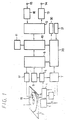
- FIG. 1 is a structural diagram showing a recording and reproducing apparatus to which one embodiment is applied.
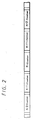
- FIG. 2 is an explanatory diagram showing a cluster forming state according to one embodiment.
- FIG. 3 is a structural diagram showing an address-data storing state according to one embodiment.
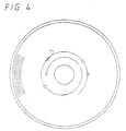
- FIG. 4 is a schematic diagram used to explain a track forming state according to one embodiment.
- FIG. 5 is a schematic diagram used to explain the track forming state according to one embodiment.
- FIG. 6 is a flowchart showing a recording processing according to one embodiment.
- the present invention is applied to a recording and reproducing apparatus of a magneto-optical disc on which an audio data is recorded.
- Construction of the recording and reproducing apparatus is shown in FIG. 1.
- reference numeral (1) represents a magneto-optical disc.
- the magneto-optical disc (1) is loaded on the recording and reproducing apparatus and rotated by a spindle motor (3) with being housed in a cartridge (2).
- a recorded signal recorded by a magnetic-field modulation method, which will be described later, on a track formed in a spiral fashion on the disc (1) is read by an optical pickup (4), and a reproduced signal is supplied through an RF amplifier (5) to a modulation and demodulation processing circuit (6) to demodulate the data modulated for the recording.
- a digital modulation called an 8-14 modulation (EFM), for example is performed.
- EFM 8-14 modulation
- the processing in the modulation and demodulation processing circuit (6) is controlled by a system controller (20).
- an address data is previously recorded by wobbling (meanderring), and this wobbling information is detected by an address decoder (9). That is, the reproduced signal output by the RF amplifier (5) is supplied to the address decoder (9), and the decoder (9) decodes the address data recorded by the wobbling to supply the decoded address data through the modulation and demodulation processing circuit (6) to the system controller (20).
- the audio data demodulated by the modulation and demodulation processing circuit (6) is supplied to a memory controller (10) and once stored in an RAM (11) connected to the memory controller (10).
- the RAM (11) is a data buffer for continuing an output of the audio data in case of the reproduced data being broken temporarily, and the data stored in the RAM (11) is supplied to a compression and expansion processing circuit (12). Then, the data compressed for the recording is expanded into an original data amount thereof by the compression and expansion processing circuit (12), and the expanded data is converted by a digital / analog converter (13) into an analog audio signal to supply the analog audio signal to an audio signal output terminal (14).
- the movements of the optical pickup (4) and a recording head (18), which will be described later, in a radius direction of the disc are carried out by the drive of a feed motor (8) under the control of a servo controlling circuit (7) based on a command from the system controller (20).
- the servo controlling circuit (7) is supplied with the reproduced signal output from the RF amplifier (5) and performs servo control to make the optical pickup and the recording head follow the reproducing track.
- the spindle motor (3) is also rotated by the control of the servo controlling circuit (7).
- the recording system is constructed such that after the analog audio signal obtained at an audio signal input terminal (15) is converted by an analog / digital converter (16) into a digital audio data, the digital audio data is subjected to a compression processing by the compression and expansion processing circuit (12), the compressed audio data is supplied to the memory controller (10) and once stored in the RAM (11) connected to the memory controller (10), the audio data read out from the RAM (11) is modulated for the recording by the modulation and demodulation processing circuit (6), and the modulated audio data is supplied to a head driving circuit (17) to drive the recording head (magnetic head) (18).
- the recording head (18) is disposed just above a position where a laser is irradiated on the disc (1) from the optical pickup (4) (opposite side of the disc). Upon recording, there is performed a processing in which a magnetic field generated by the recording head (18) is recorded while a recording portion is heated by a laser beam irradiated on the disc (1) from the optical pickup (4).
- the recording processing is one called a magnetic-field modulation recording system.
- the system controller (20) is connected with an operation key (21), and the recording and reproduction are controlled on the basis of an operation by the operation key (21). Further, the system controller (20) is connected with a display unit (30) formed of a liquid crystal display, which displays a data concerning the recording and reproduction by a letter, a number or the like.
- the system controller (20) Upon the recording of the data, the system controller (20) also discriminates existence or absence of a defect of a track under recording. That is, during the recording of the data, the wobbling information (the address data) of the track under recording which is read by the optical pickup (4) is detected by the address decoder (9). The address data detected by the address decoder (9) is checked by the system controller (20) during recording, which discriminates whether or not the detected address is kept continued and determines a portion lacking the address data as the defective section in case of existence of a portion where the detected address is discontinuous.
- a state of a tracking error signal (signal indicating the tracking of the recording track) detected by the servo controlling circuit 7 on the basis of the signal read by the optical pickup (4) is discriminated by the system controller (20), which also determines a corresponding portion as the defective section in case of detection of a large turbulence of the tracking signal.
- a subdata can be recorded besides the audio data.
- the subdata is recorded in a most inner periphery track in a predetermined format.
- the subdata recorded in the predetermined track is reproduced and then stored in a memory in the system controller (20). Then, a recording address and a reproducing address for the recording and reproduction, respectively, are controlled on the basis of the subdata.
- the audio data When the audio data is recorded, there is performed such a processing that a data such as a recorded address or the like is added to the subdata (that is, the subdata of a corresponding area is processed for updating). Only the subdata is often updated by an editing or the like.
- Content of the subdata and data arrangement thereof will be explained here.
- a setting state of the track number set in the disc (1) the address data of each track number and a data concerning kinds of the recorded data are recorded.
- data of the cluster number and the sector number are recorded.
- the cluster will be explained.
- One unit such that the track formed on the disc (1) is divided by a predetermined section is defined as one cluster, and as shown in FIG. 2, the number is successively given to each cluster from the inner periphery side (in FIG. 2, reference letter n represents an optional number).
- the recording is performed by defining one cluster as a minimum unit.
- the subdata thus recorded in the most inner periphery track is one called a TOC (Table of Contents: index informations).
- Each subdata is divided into areas each having 8 bits and recorded as shown in FIG. 3.
- the track number described here is the number given to each of recording units into which the audio data recorded on the disc (1) is divided, for example, the number given to every music in case of a plurality of music being recorded in one disc. The number does not have any direct relation with the track number of the data recording track formed on the disc (1).
- a block of the audio data of the above-mentioned one recording unit is defined as a program.
- the data to be recorded on the disc is not required to be recorded with the physically continuous addresses and may be discretely recorded.
- the data is continuously recorded in such a manner that the first music of the track number is defined as T1 and the second music thereof is defined as T2.
- the data may be discretely recorded, so that as shown in FIG. (5), the data can be discretely recorded on the disc as shown by T4 (1) to T4 (4) and T5 (1) to T5 (4) which are respectively defined as the fourth music of the track number and the fifth music thereof.
- FIG. 4 and 5 are schematically shown, and practically one section is recorded in a concentric or spiral fashion over several to several hundred circles.
- the reason why the data can be discretely recorded as described above is that since the data is once stored in the RAM (11) and then recorded on the disc, even if the recording head is accesses T4 (2) of the fourth music from T4 (1) thereof and then the data thereof is recorded on the disc as shown in FIG. 5 mentioned above, there is enough time for such process.
- the TOC (Table of Contents: the index informations) managing the above-mentioned discretely recorded data is formed of the address data at every track number and the data concerning the kind of the recorded data.
- N audio data from the track number 1 to the track number N (reference letter N represents an optional integer) are recorded on the disc (1), then a data indicating which area the address data of the track number 1 is stored in is recorded in an area 49, and hereinafter data indicating the recording areas of the address data of the corresponding track numbers to the track number N are successively recorded in the areas one by one.
- a start address of the part is recorded in the first three areas.
- a classification data is recorded in the next one area.
- An end address of the part is recorded in the next three areas.
- a connection data is recorded in the next one area.
- the above-mentioned part corresponds to one block of the discretely recorded data (T4 (1) in FIG. 5, for example, or the like), for example.
- start address and end address correspond to an absolute address of one block of the discretely recorded data on the disc, for example.
- connection data is a data for connecting the respective parts. If music of corresponding track number is formed of one or a plurality of parts, then 00 is recorded as the connection data of the last part, so that 00 is discriminated to thereby determine the end of the music.
- classification data classification of the audio data to be recorded (distinction between a stereophonic data and a monophonic data, existence or absence of a copy guard, on or off of emphasis or the like) is recorded.
- a P-FRA Pointer for the Freely Area 48 indicating which address on the above-mentioned index information the recordable area begins with.
- the address in the above-mentioned index information indicating a part corresponding to a head of the recordable area (which corresponds to an F(1) shown by a broken line in FIG. 5, for example) is recorded.
- a start address of the recordable area is recorded.
- a classification data is recorded in the next one area.
- An end address of the part is recorded in the next three areas.
- a connection data is recorded in the next one area. If the recordable areas discretely lie on the disc (see FIG. 5), the respective recordable areas are connected to each other by the connection data. Upon recording, the recording is performed while the above-mentioned index informations are retrieved.
- a P-DFA (Pointer for the Defective area) 46 indicating a defect on the disc is further recorded in the above-mentioned index information.
- an address in the index information managing the defective area on the disc is stored therein, so that the connection data of the part indicated by the above-mentioned address is searched, whereby it can be managed where the defective area is located on the disc.
- 255 parts as the index information can be managed, and a P-Empty (Pointer for the empty slot on the parts table) 47 indicating a use state of the above-mentioned part is recorded.
- the above-mentioned P-Empty indicates a head part of unused parts in the above-mentioned index information, and the unused parts are connected to each other by the connection data.
- the recording address is controlled so that the recording is carried out except for the defective section.
- a processing upon recording in case of the recording of the audio signal will hereinafter be explained with reference to a flowchart in FIG. 6.
- step 101 If there is a command for starting the recording (at step 101), then it is determined whether or not a recording data of one cluster unit which is a minimum unit of the recording data is stored in the RAM (11) (at step 102). If the recording data of one cluster amount is stored therein, then the optical pickup (4) and the recording head (18) access a cluster on the disc (1) in which the data can be recorded (at step 103) and the recording of the data is started (at step 104). At this time, it is simultaneously determined from discontinuity of the reproduced address data and the turbulence of the tracking error signal whether or not a section having a defect is detected (at step 105). If the defect is not detected, then the recording is continued as it is.
- step 107 it is determined whether or not the recording is continued. If it is determined that the recording is continued, then the process is returned to step 102 and the recording in each cluster is continued. Alternatively, if it is determined at step 107 that the recording is stopped, then the processing for finishing the recording is performed. As the processing for finishing the recording, there is performed such processing that the number of the head cluster of the recorded clusters and the number of the last cluster thereof are added to the subdata as the start address and the end address of the address data recorded in the most inner periphery track (see FIG. 3), respectively.
- the recording at this time is stopped and data of the start address and the end address of the address data to be recorded in the most inner periphery track (see FIG. 3) are made (at step 108) on the basis of the recording state up to the just before cluster.
- the connection data is added following the end address, and the connection data indicates the part number which begins with a cluster two-cluster ahead.
- the data of one cluster amount stored in the RAM (11) is recorded in the cluster two-cluster ahead (at step 109). After the recording of the data of one cluster amount is finished, the process is returned to a data recording processing for the next cluster.
- the address data is added at step 108, whereby a one-cluster previous n-1 cluster is defined as the end address and the connection data indicates such part number that the recording begins with an n+1 cluster one-cluster ahead. Then, the recording is continued from the n+1 cluster.
- the recording processing is thus performed, whereby if there is the defective section, then such processing that the data is recorded with the cluster having the defect being avoided is performed, and the connection data added to the address data directs to reproduce continuously clusters before and after the cluster having the defective section. Accordingly, when the disc on which the data is thus recorded is reproduced, if a cluster just preceding the defective section is reproduced, then the address data directs to skip the next cluster, so that the processing for continuing the continuous recording from the cluster next to the defective section is performed. Therefore, even if the disc (1) has a partial defect, then the data can be correctly recorded and reproduced without causing the lack of the recording data.
- the reproduced data is once stored in the RAM (11) and then subjected to an expansion processing to reproduce the same, so that if an access position of the optical pickup (4) is moved by one cluster amount while the reproduced data is stored in the RAM (11), then the sound to be reproduced is prevented from breaking off.
- the defective section is discriminated by detecting the turbulence of the tracking error signal detected by the optical system and detecting the discontinuity of the address information reproduced from the recording track, so that the defective section can be discriminated with satisfactory accuracy.
- the defective section may be discriminated in such a manner that when there is the turbulence of the tracking error signal or the discontinuity of the address information, the cluster is not immediately discriminated as the defect, but after the recording in the same cluster is repeated a predetermined times, when the cluster is repeatedly discriminated as the defect, the cluster is decided as the defective section. Such arrangement allows the defective section to be more reliably discriminated.
- the defective section if there is the defective section, then the defective section is not registered especially in the index information and dealt with as an unmanaged information, while the defective section may be defined as the above-mentioned P-DFA (Pointer for the Defective area) 46 indicating the defect on the disc to register the above-mentioned defective cluster as the part.
- P-DFA Pointer for the Defective area
- the P-Empty which is the unused part is retrieved to record the start address and the end address of the above-mentioned defective cluster in the above-mentioned unused part and if the defective section is the first defective area, then the address data of the above-mentioned registered part is recorded in the P-DFA.
- address data is all recorded only in the most inner periphery track, the address data may be recorded in another portion.
- the present invention can be applied to the case where another data such as a video data, a program data or the like are recorded on the disc.
Landscapes
- Engineering & Computer Science (AREA)
- Signal Processing (AREA)
- Multimedia (AREA)
- Signal Processing For Digital Recording And Reproducing (AREA)
- Optical Recording Or Reproduction (AREA)
Abstract
Applications Claiming Priority (7)
| Application Number | Priority Date | Filing Date | Title |
|---|---|---|---|
| JP205594/92 | 1992-07-31 | ||
| JP20559492 | 1992-07-31 | ||
| JP20559492 | 1992-07-31 | ||
| JP294317/92 | 1992-11-02 | ||
| JP29431792 | 1992-11-02 | ||
| JP29431792 | 1992-11-02 | ||
| PCT/JP1993/001072 WO1994003891A1 (fr) | 1992-07-31 | 1993-07-30 | Dispositif et procede d'enregistrement sur disque |
Publications (3)
| Publication Number | Publication Date |
|---|---|
| EP0606499A1 true EP0606499A1 (fr) | 1994-07-20 |
| EP0606499A4 EP0606499A4 (fr) | 1995-02-22 |
| EP0606499B1 EP0606499B1 (fr) | 2001-10-17 |
Family
ID=26515146
Family Applications (1)
| Application Number | Title | Priority Date | Filing Date |
|---|---|---|---|
| EP93916244A Expired - Lifetime EP0606499B1 (fr) | 1992-07-31 | 1993-07-30 | Dispositif et procede d'enregistrement sur disque |
Country Status (7)
| Country | Link |
|---|---|
| US (2) | US5553045A (fr) |
| EP (1) | EP0606499B1 (fr) |
| JP (1) | JP3528179B2 (fr) |
| KR (1) | KR100295219B1 (fr) |
| CA (1) | CA2120352C (fr) |
| DE (1) | DE69330941T2 (fr) |
| WO (1) | WO1994003891A1 (fr) |
Cited By (1)
| Publication number | Priority date | Publication date | Assignee | Title |
|---|---|---|---|---|
| WO2001006510A1 (fr) * | 1999-07-15 | 2001-01-25 | Koninklijke Philips Electronics N.V. | Procede d'analyse d'un disque d'enregistrements en cas de defauts, et dispositif d'enregistrement pour enregistrer des informations sur un support d'enregistrement en forme de disque |
Families Citing this family (69)
| Publication number | Priority date | Publication date | Assignee | Title |
|---|---|---|---|---|
| JP3113200B2 (ja) * | 1996-03-25 | 2000-11-27 | 株式会社東芝 | 交替処理方法 |
| JP3029399B2 (ja) * | 1996-03-25 | 2000-04-04 | 株式会社東芝 | 交替処理方法 |
| JP3113201B2 (ja) * | 1996-03-25 | 2000-11-27 | 株式会社東芝 | 交替処理方法 |
| JP3029400B2 (ja) * | 1996-03-25 | 2000-04-04 | 株式会社東芝 | 交替処理方法 |
| JP2848809B2 (ja) * | 1996-03-25 | 1999-01-20 | 株式会社東芝 | 交替処理方法 |
| US6278807B1 (en) * | 1997-11-13 | 2001-08-21 | Kabushiki Kaisha Toshiba | Data recording/reproducing apparatus, data recording/reproducing method applied to the apparatus, and computer program product used in data processing apparatus |
| KR100292093B1 (ko) * | 1998-03-02 | 2001-06-01 | 구자홍 | 기록매체의 결함영역 관리자료 생성방법 및 생성장치 그리고 이에 의한 광기록매체 |
| JP3839959B2 (ja) * | 1998-06-05 | 2006-11-01 | パイオニア株式会社 | 情報再生装置、情報記録装置、情報再生方法及び情報記録方法 |
| KR100429179B1 (ko) * | 1998-07-01 | 2004-06-16 | 엘지전자 주식회사 | 광기록매체의결함영역관리장치및그방법 |
| BRPI9906653B1 (pt) * | 1998-07-28 | 2015-08-25 | Lg Electronics Inc | Meio de gravação ótica, método para o gerenciamento de blocos com defeito dentro de uma área de dados de usuário de um meio de gravação ótica e aparelho para gravação de dados |
| KR100407931B1 (ko) * | 1998-07-29 | 2004-03-30 | 엘지전자 주식회사 | 실시간기록/재생시의파일관리방법및실시간데이터기록방법및그광기록/재생매체 |
| US6496876B1 (en) * | 1998-12-21 | 2002-12-17 | Micron Technology, Inc. | System and method for storing a tag to identify a functional storage location in a memory device |
| KR100677064B1 (ko) | 1999-04-21 | 2007-02-01 | 삼성전자주식회사 | 끊어짐없이 데이터를 저장하는 광 기록 매체와 그 결함 영역 처리 방법 |
| KR100544175B1 (ko) * | 1999-05-08 | 2006-01-23 | 삼성전자주식회사 | 링킹 타입 정보를 저장하는 기록 매체와 결함 영역 처리 방법 |
| MXPA02004748A (es) * | 1999-11-10 | 2004-01-19 | Thomson Licensing Sa | Un metodo para la recuperacion de desastre para un medio de disco de re-escritrua. |
| KR100378165B1 (ko) * | 2000-11-27 | 2003-03-29 | 삼성전자주식회사 | 링킹 손실 영역에 데이터를 오버라이팅 하는 방법 |
| KR20030014753A (ko) * | 2001-05-09 | 2003-02-19 | 코닌클리케 필립스 일렉트로닉스 엔.브이. | 미디어 파일을 재생하는 시스템 및 방법 |
| US20030161980A1 (en) * | 2002-02-27 | 2003-08-28 | Nelson Brent S. | Plastic container |
| JP2003308644A (ja) * | 2002-04-09 | 2003-10-31 | Toshiba Corp | ディスク記憶装置及び同装置における代替セクタアクセス方法 |
| KR100878523B1 (ko) * | 2002-05-20 | 2009-01-13 | 삼성전자주식회사 | 드라이브 정보 기록 방법 및 광디스크 |
| KR20040015425A (ko) * | 2002-08-12 | 2004-02-19 | 삼성전자주식회사 | 결함 관리를 적용한 1회 기록용 고밀도 기록 매체, 결함관리 방법 및 그 장치 |
| CA2480064C (fr) | 2002-09-26 | 2013-01-22 | Lg Electronics Inc. | Procede de gestion d'une zone defectueuse sur un support d'enregistrement optique a ecriture unique et support d'enregistrement optique l'utilisant |
| AU2003264977B2 (en) | 2002-09-26 | 2009-03-26 | Lg Electronics Inc. | Optical disc, method and apparatus for managing a defective area on an optical disc of write once type |
| KR20040027259A (ko) | 2002-09-26 | 2004-04-01 | 엘지전자 주식회사 | 1 회 기록 가능한 광디스크의 디펙트 영역 관리방법 |
| US7233550B2 (en) | 2002-09-30 | 2007-06-19 | Lg Electronics Inc. | Write-once optical disc, and method and apparatus for recording management information on write-once optical disc |
| KR20040028469A (ko) | 2002-09-30 | 2004-04-03 | 엘지전자 주식회사 | 1 회 기록 가능한 광디스크의 디펙트 영역 관리방법 |
| KR100667749B1 (ko) * | 2002-10-18 | 2007-01-11 | 삼성전자주식회사 | 임시 결함 관리 영역을 사용한 결함 관리 방법, 그 장치및 그디스크 |
| AU2003282448A1 (en) | 2002-12-11 | 2004-06-30 | Lg Electronics Inc. | Method and apparatus for managing overwrite on an optical disc write once |
| ATE462184T1 (de) | 2002-12-11 | 2010-04-15 | Lg Electronics Inc | Überschreibverfahren und informationsaufzeichnungsverfahren für eine einmalig beschreibbare optische diskette |
| US7355934B2 (en) | 2003-01-27 | 2008-04-08 | Lg Electronics Inc. | Optical disc of write once type, method, and apparatus for managing defect information on the optical disc |
| US7372788B2 (en) | 2003-01-14 | 2008-05-13 | Lg Electronics Inc. | Method for managing defective area on write-once optical recording medium, and optical recording medium using the same |
| US7672204B2 (en) | 2003-01-27 | 2010-03-02 | Lg Electronics Inc. | Optical disc, method and apparatus for managing a defective area on an optical disc |
| US20040160799A1 (en) * | 2003-02-17 | 2004-08-19 | Park Yong Cheol | Write-once optical disc, and method and apparatus for allocating spare area on write-once optical disc |
| US7499383B2 (en) | 2003-02-21 | 2009-03-03 | Lg Electronics Inc. | Write-once optical disc and method for managing spare area thereof |
| TWI335587B (en) | 2003-02-21 | 2011-01-01 | Lg Electronics Inc | Write-once optical recording medium and defect management information management method thereof |
| TWI278851B (en) | 2003-02-25 | 2007-04-11 | Lg Electronics Inc | Recording medium having data structure for managing at least a data area of the recording medium and recording and reproducing methods and apparatuses |
| US7188271B2 (en) | 2003-02-25 | 2007-03-06 | Lg Electronics Inc. | Write-once optical disc, and method and apparatus for recording management information on write-once optical disc |
| TWI291168B (en) * | 2003-02-25 | 2007-12-11 | Lg Electronics Inc | Defect management method for optical recording medium and optical recording medium using the same |
| BRPI0318160B1 (pt) | 2003-03-04 | 2016-05-31 | Lg Electronics Inc | método para gravação em meio de gravação óptica, aparelho para gravação em e reprodução de um meio de gravação óptica e meio de gravação óptica |
| TWI328805B (en) | 2003-03-13 | 2010-08-11 | Lg Electronics Inc | Write-once recording medium and defective area management method and apparatus for write-once recording medium |
| MXPA05012044A (es) | 2003-05-09 | 2006-02-03 | Lg Electronics Inc | Disco optico de una sola escritura, metodo y aparato par recuperacion de informacion de administracion de disco del disco optico de una sola escritura. |
| US7663997B2 (en) | 2003-05-09 | 2010-02-16 | Lg Electronics, Inc. | Write once optical disc, and method and apparatus for recovering disc management information from the write once optical disc |
| AU2004237018B2 (en) | 2003-05-09 | 2009-09-10 | Lg Electronics Inc. | Recording medium having data structure for managing at least a data area of the recording medium and recording and reproducing methods and apparatuses |
| BRPI0410196A (pt) | 2003-05-09 | 2006-05-23 | Lg Electronics Inc | meio fìsico de gravação, método e aparelho para gravar dados de gerenciamento em meio fìsico de gravação, método de reproduzir dados de meio fìsico de gravação |
| WO2005004123A1 (fr) | 2003-07-04 | 2005-01-13 | Lg Electronics Inc. | Procede et appareil de traitement d'un enregistrement avec ecrasement sur un disque optique monosession |
| JP4750027B2 (ja) | 2003-07-14 | 2011-08-17 | エルジー エレクトロニクス インコーポレイティド | 追記型光ディスク、追記型光ディスクにおける管理情報の記録方法並びに装置 |
| KR101014703B1 (ko) | 2003-07-15 | 2011-02-21 | 엘지전자 주식회사 | 광디스크의 결함영역 관리방법 및 광디스크의 기록방법과기록재생장치 |
| KR20050009031A (ko) | 2003-07-15 | 2005-01-24 | 엘지전자 주식회사 | 1회 기록 가능한 광디스크 및 광디스크의 관리정보 기록방법 |
| US7313065B2 (en) | 2003-08-05 | 2007-12-25 | Lg Electronics Inc. | Write-once optical disc, and method and apparatus for recording/reproducing management information on/from optical disc |
| DE602004025947D1 (de) | 2003-08-05 | 2010-04-22 | Lg Electronics Inc | Einmalbeschreibbarer optischer datenträger und verfahren und vorrichtung zum aufzeichnen/wiedergeben von verwaltungsinformationen auf dem optischen datenträger bzw. daraus |
| EP1665259B1 (fr) | 2003-09-08 | 2013-11-06 | LG Electronics Inc. | Disque optique a ecriture unique et procede d'enregistrement d'informations de gestion sur un tel disque |
| JP2007505432A (ja) | 2003-09-08 | 2007-03-08 | エルジー エレクトロニクス インコーポレーテッド | 追記型光ディスク、並びにその上に管理情報を記録するための方法及び装置 |
| WO2005024793A2 (fr) | 2003-09-08 | 2005-03-17 | Lg Electronics Inc. | Disque optique a ecriture unique, procede et appareil d'enregistrement d'informations de gestion sur ledit disque |
| KR100964685B1 (ko) | 2003-10-20 | 2010-06-21 | 엘지전자 주식회사 | 1회 기록가능한 광디스크 및 광디스크의 기록재생방법과기록재생장치 |
| KR101113866B1 (ko) | 2004-03-19 | 2012-03-02 | 엘지전자 주식회사 | 기록매체내에 기록되는 데이터 구조 및 데이터 기록방법과기록장치 |
| KR101024916B1 (ko) | 2004-03-19 | 2011-03-31 | 엘지전자 주식회사 | 1회 기록 가능한 고밀도 광디스크의 데이터 기록 방법 및장치 |
| US7630167B2 (en) * | 2004-05-10 | 2009-12-08 | Samsung Electronics Co., Ltd. | Method and apparatus to detect sub-micron particles in a hard disk drive with optical pickup |
| KR101049117B1 (ko) | 2004-06-08 | 2011-07-14 | 엘지전자 주식회사 | 1회 기록 가능한 광디스크 및 광디스크의 관리정보 기록방법, 디스크 클로징 방법 및 기록재생 장치 |
| KR101014727B1 (ko) * | 2004-06-23 | 2011-02-16 | 엘지전자 주식회사 | 1회 기록 가능한 광디스크의 중첩 기록 방법 및 장치 |
| JP4285344B2 (ja) * | 2004-07-08 | 2009-06-24 | ソニー株式会社 | 情報記録装置および方法、プログラム格納媒体、並びにプログラム |
| KR101041811B1 (ko) | 2004-08-02 | 2011-06-17 | 엘지전자 주식회사 | 광 저장매체의 기록 재생 방법 및 장치 |
| KR101012378B1 (ko) | 2004-08-16 | 2011-02-09 | 엘지전자 주식회사 | 광 저장매체의 기록 재생 방법 및 장치 |
| KR101215370B1 (ko) | 2004-09-14 | 2012-12-26 | 엘지전자 주식회사 | 기록매체 및 기록매체의 기록 재생 방법 및 장치 |
| JP2006107622A (ja) * | 2004-10-05 | 2006-04-20 | Toshiba Corp | ライトワンスメディアへの記録方法、記録装置および再生装置 |
| US7613874B2 (en) | 2004-10-14 | 2009-11-03 | Lg Electronics, Inc. | Recording medium, and a method and apparatus for overwriting data in the same |
| US20060239152A1 (en) * | 2005-04-25 | 2006-10-26 | Mediatek Incorporation | Disc recording methods and systems |
| KR101227485B1 (ko) | 2005-11-25 | 2013-01-29 | 엘지전자 주식회사 | 기록매체 및 기록매체의 결함관리 정보 기록방법과기록장치 |
| KR20070058291A (ko) | 2005-12-02 | 2007-06-08 | 엘지전자 주식회사 | 기록매체, 기록매체의 관리정보 기록방법 및 기록장치 |
| US20070230302A1 (en) * | 2006-03-28 | 2007-10-04 | Media Tek Inc. | Optical disc recording protection |
Family Cites Families (18)
| Publication number | Priority date | Publication date | Assignee | Title |
|---|---|---|---|---|
| EP0127311B1 (fr) * | 1983-05-23 | 1990-03-14 | Data General Corporation | Procédé et dispositif de commande pour le traitement de défauts du support d'enregistrement dans un système de mémoire |
| JPS60202573A (ja) * | 1984-03-28 | 1985-10-14 | Mitsubishi Electric Corp | 光デイスクの再記録制御方式 |
| JP2771974B2 (ja) * | 1986-08-29 | 1998-07-02 | 株式会社東芝 | 情報記録媒体 |
| JPS6363167A (ja) * | 1986-09-02 | 1988-03-19 | Canon Inc | 情報記録再生装置 |
| JPS63113979A (ja) * | 1986-10-31 | 1988-05-18 | Toshiba Corp | 光ディスク装置の欠陥管理方式 |
| DE3787452T2 (de) * | 1986-12-19 | 1994-01-13 | Matsushita Electric Ind Co Ltd | Löschbare optische Platte und Gerät zur Aufnahme und Wiedergabe optischer Informationen mit Einrichtung zur Handhabung defekter Sektoren. |
| JPS63179471A (ja) * | 1987-01-20 | 1988-07-23 | Sanyo Electric Co Ltd | デ−タ記録方法及びデ−タ記録/再生方法 |
| JP2848528B2 (ja) * | 1989-02-16 | 1999-01-20 | オリンパス光学工業株式会社 | 光ディスクドライブ装置 |
| JP3065631B2 (ja) * | 1990-02-28 | 2000-07-17 | オリンパス光学工業株式会社 | 光ディスクドライブ装置 |
| US5353276A (en) * | 1990-03-12 | 1994-10-04 | Deutsche Thomson-Brandt Gmbh | Process for recording and/or reproducing digital data on a record carrier |
| JPH0428061A (ja) * | 1990-05-24 | 1992-01-30 | Matsushita Electric Ind Co Ltd | 情報記録媒体と情報記録再生装置 |
| US5255270A (en) * | 1990-11-07 | 1993-10-19 | Emc Corporation | Method of assuring data write integrity on a data storage device |
| JP3021029B2 (ja) * | 1990-11-20 | 2000-03-15 | シャープ株式会社 | 光磁気記録媒体の情報アクセス方法 |
| JPH04370572A (ja) * | 1991-06-18 | 1992-12-22 | Pioneer Electron Corp | 記録媒体及びこれを用いたビデオ信号記録再生方法 |
| US5303219A (en) * | 1991-09-09 | 1994-04-12 | International Business Machines Corporation | Reclamation of dust contaminated sectors in optical disk apparatus |
| US5235585A (en) * | 1991-09-11 | 1993-08-10 | International Business Machines | Reassigning defective sectors on a disk |
| JPH0658670A (ja) * | 1991-10-07 | 1994-03-04 | Kawasaki Steel Corp | 金属粉の連続熱処理用ベルト炉 |
| JPH0710709B2 (ja) * | 1993-03-09 | 1995-02-08 | 左近紙工株式会社 | パレット状商品ケースの製造方法 |
-
1993
- 1993-07-30 CA CA002120352A patent/CA2120352C/fr not_active Expired - Fee Related
- 1993-07-30 US US08/211,260 patent/US5553045A/en not_active Expired - Lifetime
- 1993-07-30 KR KR1019940701044A patent/KR100295219B1/ko not_active Expired - Fee Related
- 1993-07-30 WO PCT/JP1993/001072 patent/WO1994003891A1/fr not_active Ceased
- 1993-07-30 EP EP93916244A patent/EP0606499B1/fr not_active Expired - Lifetime
- 1993-07-30 DE DE69330941T patent/DE69330941T2/de not_active Expired - Fee Related
- 1993-07-30 JP JP50517994A patent/JP3528179B2/ja not_active Expired - Fee Related
-
1997
- 1997-10-28 US US08/959,724 patent/US6058085A/en not_active Expired - Fee Related
Cited By (4)
| Publication number | Priority date | Publication date | Assignee | Title |
|---|---|---|---|---|
| WO2001006510A1 (fr) * | 1999-07-15 | 2001-01-25 | Koninklijke Philips Electronics N.V. | Procede d'analyse d'un disque d'enregistrements en cas de defauts, et dispositif d'enregistrement pour enregistrer des informations sur un support d'enregistrement en forme de disque |
| US7215619B1 (en) * | 1999-07-15 | 2007-05-08 | Koninklijke Philips Electronics, N.V. | Method of scanning a recording disc for defects, and recording device for recording information on a disc-shaped recording medium |
| CN1328725C (zh) * | 1999-07-15 | 2007-07-25 | 皇家菲利浦电子有限公司 | 扫描记录盘发现缺陷的方法和在盘形记录媒体上记录信息的记录设备 |
| EP2178088A3 (fr) * | 1999-07-15 | 2011-10-26 | Koninklijke Philips Electronics N.V. | Procédé d'analyse d'un disque d'enregistrements en cas de defauts, et dispositif d'enregistrement pour enregistrer des informations sur un support d'enregistrement en forme de disque |
Also Published As
| Publication number | Publication date |
|---|---|
| EP0606499B1 (fr) | 2001-10-17 |
| WO1994003891A1 (fr) | 1994-02-17 |
| CA2120352C (fr) | 2002-10-29 |
| US6058085A (en) | 2000-05-02 |
| JP3528179B2 (ja) | 2004-05-17 |
| US5553045A (en) | 1996-09-03 |
| DE69330941T2 (de) | 2002-04-25 |
| EP0606499A4 (fr) | 1995-02-22 |
| CA2120352A1 (fr) | 1994-02-17 |
| KR100295219B1 (ko) | 2001-09-17 |
| DE69330941D1 (de) | 2001-11-22 |
Similar Documents
| Publication | Publication Date | Title |
|---|---|---|
| US6058085A (en) | Method and apparatus for identifying and skipping defective sections | |
| KR100373618B1 (ko) | 디스크형기록매체,기록장치및재생장치 | |
| US5825726A (en) | Multi-session disc and a high-speed access method thereto | |
| JPWO1994003891A1 (ja) | ディスク記録装置及びディスク記録方法 | |
| EP0406021A2 (fr) | Appareil d'enregistrement/reproduction pour disque | |
| US5706262A (en) | Recording and reproducing apparatus that allows user reordering of the sequence that data is reproduced from the disc and that automatically reorders the remaining data after data defined by the user has been erased | |
| EP0376756A2 (fr) | Dispositif d'enregistrement/de reproduction | |
| US5126987A (en) | Information reproducing apparatus | |
| US5974018A (en) | Apparatus for and method of recording information on recording media | |
| US6556518B2 (en) | Optical disk recording apparatus and method | |
| JP2727837B2 (ja) | 光ディスクの再生方法 | |
| JP2704998B2 (ja) | 光ディスク記録装置 | |
| JP2576964B2 (ja) | 光ディスク記録装置 | |
| JP2704997B2 (ja) | 光ディスク記録装置 | |
| JP3435707B2 (ja) | 再生装置 | |
| JP2704996B2 (ja) | 光ディスク記録装置 | |
| JP2704995B2 (ja) | 光ディスク記録装置 | |
| JP3439589B2 (ja) | 記録再生装置 | |
| JP3481102B2 (ja) | 光ディスク用記録装置 | |
| JP3163782B2 (ja) | 記録装置 | |
| JPH09147532A (ja) | ディスク記録装置 | |
| JP3163781B2 (ja) | 記録装置、記録方法 | |
| JPH0676483A (ja) | ディスク記録装置 | |
| JPH07114787A (ja) | ミニディスクの無音部分自動消去方法 | |
| JPH09312085A (ja) | 情報記録再生装置及び情報記録再生方法 |
Legal Events
| Date | Code | Title | Description |
|---|---|---|---|
| PUAI | Public reference made under article 153(3) epc to a published international application that has entered the european phase |
Free format text: ORIGINAL CODE: 0009012 |
|
| 17P | Request for examination filed |
Effective date: 19940329 |
|
| AK | Designated contracting states |
Kind code of ref document: A1 Designated state(s): DE FR GB |
|
| A4 | Supplementary search report drawn up and despatched | ||
| AK | Designated contracting states |
Kind code of ref document: A4 Designated state(s): DE FR GB |
|
| 17Q | First examination report despatched |
Effective date: 19961030 |
|
| GRAG | Despatch of communication of intention to grant |
Free format text: ORIGINAL CODE: EPIDOS AGRA |
|
| GRAG | Despatch of communication of intention to grant |
Free format text: ORIGINAL CODE: EPIDOS AGRA |
|
| GRAH | Despatch of communication of intention to grant a patent |
Free format text: ORIGINAL CODE: EPIDOS IGRA |
|
| GRAH | Despatch of communication of intention to grant a patent |
Free format text: ORIGINAL CODE: EPIDOS IGRA |
|
| GRAA | (expected) grant |
Free format text: ORIGINAL CODE: 0009210 |
|
| AK | Designated contracting states |
Kind code of ref document: B1 Designated state(s): DE FR GB |
|
| REF | Corresponds to: |
Ref document number: 69330941 Country of ref document: DE Date of ref document: 20011122 |
|
| REG | Reference to a national code |
Ref country code: GB Ref legal event code: IF02 |
|
| ET | Fr: translation filed | ||
| PLBE | No opposition filed within time limit |
Free format text: ORIGINAL CODE: 0009261 |
|
| STAA | Information on the status of an ep patent application or granted ep patent |
Free format text: STATUS: NO OPPOSITION FILED WITHIN TIME LIMIT |
|
| 26N | No opposition filed | ||
| PGFP | Annual fee paid to national office [announced via postgrant information from national office to epo] |
Ref country code: FR Payment date: 20090710 Year of fee payment: 17 |
|
| PGFP | Annual fee paid to national office [announced via postgrant information from national office to epo] |
Ref country code: GB Payment date: 20090729 Year of fee payment: 17 Ref country code: DE Payment date: 20090723 Year of fee payment: 17 |
|
| GBPC | Gb: european patent ceased through non-payment of renewal fee |
Effective date: 20100730 |
|
| REG | Reference to a national code |
Ref country code: FR Ref legal event code: ST Effective date: 20110331 |
|
| PG25 | Lapsed in a contracting state [announced via postgrant information from national office to epo] |
Ref country code: DE Free format text: LAPSE BECAUSE OF NON-PAYMENT OF DUE FEES Effective date: 20110201 |
|
| REG | Reference to a national code |
Ref country code: DE Ref legal event code: R119 Ref document number: 69330941 Country of ref document: DE Effective date: 20110201 |
|
| PG25 | Lapsed in a contracting state [announced via postgrant information from national office to epo] |
Ref country code: FR Free format text: LAPSE BECAUSE OF NON-PAYMENT OF DUE FEES Effective date: 20100802 |
|
| PG25 | Lapsed in a contracting state [announced via postgrant information from national office to epo] |
Ref country code: GB Free format text: LAPSE BECAUSE OF NON-PAYMENT OF DUE FEES Effective date: 20100730 |