EP0606543B1 - Dispositif anti-éblouissant - Google Patents
Dispositif anti-éblouissant Download PDFInfo
- Publication number
- EP0606543B1 EP0606543B1 EP93117227A EP93117227A EP0606543B1 EP 0606543 B1 EP0606543 B1 EP 0606543B1 EP 93117227 A EP93117227 A EP 93117227A EP 93117227 A EP93117227 A EP 93117227A EP 0606543 B1 EP0606543 B1 EP 0606543B1
- Authority
- EP
- European Patent Office
- Prior art keywords
- light
- glare
- deflecting
- slats
- slat
- Prior art date
- Legal status (The legal status is an assumption and is not a legal conclusion. Google has not performed a legal analysis and makes no representation as to the accuracy of the status listed.)
- Expired - Lifetime
Links
- 230000004313 glare Effects 0.000 title description 8
- XAGFODPZIPBFFR-UHFFFAOYSA-N aluminium Chemical compound [Al] XAGFODPZIPBFFR-UHFFFAOYSA-N 0.000 claims description 3
- 229910052782 aluminium Inorganic materials 0.000 claims description 3
- 239000004411 aluminium Substances 0.000 claims 1
- 238000009792 diffusion process Methods 0.000 claims 1
- 230000009286 beneficial effect Effects 0.000 description 4
- 238000004519 manufacturing process Methods 0.000 description 3
- 238000004080 punching Methods 0.000 description 3
- 230000000694 effects Effects 0.000 description 2
- 238000005516 engineering process Methods 0.000 description 2
- 230000002349 favourable effect Effects 0.000 description 2
- 241000446313 Lamella Species 0.000 description 1
- 238000005553 drilling Methods 0.000 description 1
- 230000003287 optical effect Effects 0.000 description 1
- 230000005855 radiation Effects 0.000 description 1
- 238000002310 reflectometry Methods 0.000 description 1
- 239000000725 suspension Substances 0.000 description 1
Images

Classifications
-
- E—FIXED CONSTRUCTIONS
- E06—DOORS, WINDOWS, SHUTTERS, OR ROLLER BLINDS IN GENERAL; LADDERS
- E06B—FIXED OR MOVABLE CLOSURES FOR OPENINGS IN BUILDINGS, VEHICLES, FENCES OR LIKE ENCLOSURES IN GENERAL, e.g. DOORS, WINDOWS, BLINDS, GATES
- E06B9/00—Screening or protective devices for wall or similar openings, with or without operating or securing mechanisms; Closures of similar construction
- E06B9/24—Screens or other constructions affording protection against light, especially against sunshine; Similar screens for privacy or appearance; Slat blinds
- E06B9/26—Lamellar or like blinds, e.g. venetian blinds
- E06B9/38—Other details
- E06B9/386—Details of lamellae
Definitions
- the invention relates to a glare protection device with several at a distance elongated light deflection slats arranged one above the other, on their Mirrored tops and preferably curved concave upwards in cross section are.
- the especially in the workplace especially when using screens annoying high window luminance or the resulting glare generally originate on the one hand from the high sky luminance, which also hidden sun, and reflections of sky radiation, which of course also includes direct sunlight on other buildings or on, for example, snow-covered ground.
- the high sky luminance which also hidden sun, and reflections of sky radiation, which of course also includes direct sunlight on other buildings or on, for example, snow-covered ground.
- that's up in practice light hitting a window opening is generally diffuse (i.e. it hits everyone possible directions), clearly from certain directions (e.g. the Sun or that of a white wall) higher luminance can be expected are than from others.
- Good anti-glare devices are characterized by the fact that on the one hand below a critical angle, generally the horizontal (in special applications other limit angles are possible), only a little light can enter the room and thus prevent glare at work, for example (dimming conditions), on the other hand, as much as possible let through as much light as possible in order to be without get along with artificial lighting.
- This can be done, for example, by a Anti-glare device in the form of an openable slatted blind with the top achieve mirrored and concave upward-deflecting light deflection slats, as they do is known from EP-A2-0303107.
- the object of the invention is to provide an improved anti-glare device at the beginning to create the above-mentioned genus, provided that the stopping down conditions are met certain areas of the room bring a large amount of light into the room and which on the other hand has a certain view from the room through the anti-glare device allowed outside through.
- the perforated design of the deflection slats allows a certain degree of transparency and thus enables an at least vague look through from the room Outside. At the same time, however, the desired dimming effect remains Anti-glare device received.
- the undersides of the light deflection slats are matt coated or painted to prevent glare from reflecting on the undersides Rays of light coming down at an angle below the horizontal h Avoid entering space.
- Perforated blackout slats are from EP-A-0 483,994. However, these do not work as anti-glare devices mirrored tops and matt undersides.
- the Light deflecting slats only on one extending in the longitudinal direction of the slats Stripes that take up only part of the slat width are perforated while the remaining part of the slat width is a continuous closed surface having.
- the closed, mirrored surface enables an almost complete Reflection of the light rays hitting them, during the perforated Areas naturally swallow some light. Through the you can only partially perforate the slats the closed surfaces are highly efficient and nevertheless a certain one about the perforated areas Achieve transparency.
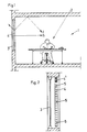
- Anti-glare device shown schematically 2 is a schematic illustration of a Embodiment of the anti-glare device according to the invention
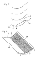
- 3 shows a schematic cross section by four light deflection slats of a further exemplary embodiment
- 4 shows an embodiment a light deflection slat according to the invention in perspective Representation
- Fig. 5 is a cross section by two light deflection slats of a further embodiment.
- Fig. 1 is arranged in a partial area of the room 1 Workplace 2 shown. Over one as a window 3 trained light entry opening gets light from outside into room 1. The inside of window 3 arranged anti-glare device 4 prevents the luminance of the Window is too high and thus causes glare. The anti-glare device 4 steers when shown Example of incident light in an essentially lying above the horizontal limit ray h Angular range around. A typical light beam path is denoted by 1.
- the anti-glare device from a schematically shown in Fig. 2 pull-up venetian blind 4, whose Light deflection slats 5 mirrored on their tops are and preferably concave over their entire length can be arched upwards. Also lies to achieve a redirection of light into the upper half space the inner longitudinal edge 5a facing the space 1 is advantageous same height (see Fig. 5) or higher (see Fig. 3 and 4) as the outer longitudinal edge 5b. Is not anti-glare necessary, the blind can be designated as 4 'in FIG. 2 Position to be pulled up.
- Fig. 3 are four superimposed light deflection slats an anti-glare device according to the invention shown.
- Anti-glare device more than four superimposed Light deflecting slats, generally via the have full window height.
- the light deflection slats 5 can or the like via pull cords, not shown. be pulled up like a slatted blind.
- the tops of the light deflection slats 5 are mirrored and in the preferred embodiment a high-gloss aluminum surface made of aluminum existing light deflection slats 5 formed.
- a high-gloss aluminum surface made of aluminum existing light deflection slats 5 formed.
- the light deflection slats have a reflectance of more than 85% with a diffuse content of less than Have 20%.
- the sheen of the mirrored Tops of the light deflecting louvers on one Beam angle of 60 ° is more than 80%.
- the undersides of the light deflection slats are matt coated or painted to glare through on the undersides reflected rays of light falling under a Angle below the horizontal h down into the room to avoid. It is beneficial if the Degree of reflection of the diffusely reflecting undersides the light deflection slats is between 30 and 50%. Such a design of the sub-pages also has an effect favorable to the partial transparency perceivable by the viewer the anti-glare device from the inside out outside, which is described in more detail below will be. Obtain the above reflectance information on the surface areas between or outside of the holes.
- the Lichtumlenklamellen 5 in itself in the longitudinal direction of the slats extending strips of width b perforated through a perforation, such as this 4, which is only a part of the Represents slat length.
- the perforated strip extends lengthways over the entire light deflection slat and in width from approximately the lowest point A to essentially up to the inner longitudinal edge 5a, which is higher than the outer Longitudinal edge 5b and in the embodiment shown in at about the lowest point of the one above Light deflection slat lies.
- the outside of the slats have a continuous mirrored surface in area a and allow thus a high efficiency of the anti-glare device. From manufacturing and optical For reasons, it may be beneficial if the on the inside Longitudinal edge 5a of the light deflecting lamella 5 adjacent area c to a width of preferably a few millimeters a continuous, not perforated surface having.
- the punching can be advantageous from a regular one Pattern of circular holes through the top view
- Light deflection slats can be formed, as shown in FIG. 4 is shown.
- the holes 6 can be advantageous Arranged rows of holes running in the longitudinal direction of the slats be offset from each other and thus perforation should be as uniform as possible. Manufacturing technology can the holes 6 for example be formed by punching or drilling.
- the hole size and the proportion of holes significantly the transparency through the anti-glare device.
- a higher percentage of holes for example Transparency from the inside out through the anti-glare device be increased through. Indeed this also reduces the overall efficiency amount of light brought into the room.
- the percentage of holes is the ratio of the total surface of the holes 6 in plan view to that between the holes lying surface of the strip of width b defined. In terms of production technology and optics, it is favorable if the maximum hole diameter is less than 2 mm, preferably less than 1 mm.
- Fig. 5 two light deflection slats 5 of an embodiment are shown schematically in cross section.
- the slat width in the present case is 80 mm and the slat distance 11 mm.
- the outer longitudinal edge 5b is the same height as the inner (room-side) longitudinal edge 5a.
- the direct light beam l 1 entering deepest below the horizontal without reflection includes only a small negative critical angle ⁇ with the horizontal X.
- the light deflection slats 5 are parts of ellipses of the focal points F 1 , F 2 on the longitudinal edges 5a, b of the light deflection slat lying above them.
- the light deflecting slats can be in a non-pivoting fixed position, which they are lowered Take the slatted blind automatically.
- a swiveling one Suspension of the light deflection slats is however also conceivable and possible.
- the invention is of course not limited to that shown Embodiments limited.
- the perforated area can spread over a larger area Range of slat widths than this in Fig. 4 is shown.
- the Punching also need not be shown in FIG. 4 Pattern.
- the holes don't need either necessarily to be circular. Rather you can for example square holes in plan view be provided to the light deflection slats perforate.
Landscapes
- Engineering & Computer Science (AREA)
- Structural Engineering (AREA)
- Architecture (AREA)
- Civil Engineering (AREA)
- Blinds (AREA)
Claims (16)
- Dispositif anti-éblouissant comportant plusieurs lamelles allongées (5) de déviation de la lumière, qui sont superposées à distance les unes des autres, sont métallisées sur leurs faces supérieures et sont cintrées de préférence avec une forme concave vers le haut en coupe transversale, caractérisé en ce que les lamelles (5) de déviation de la lumière sont perforées, au moins par endroits (b), en étant traversées par des trous, et que les faces inférieures des lamelles (5) de déviation de la lumière sont recouvertes par un revêtement mat ou une peinture mate réalisant une réflexion diffuse.
- Dispositif anti-éblouissant selon la revendication 1, caractérisé en ce que les lamelles (5) de déviation de la lumière sont perforées uniquement suivant une bande qui s'étend dans la direction longitudinale des lamelles et qui occupe simplement une partie (b) de la largeur des lamelles, tandis que la partie restante (a, c) de la largeur des lamelles possède une surface fermée continue.
- Dispositif anti-éblouissant selon la revendication 1 ou 2, caractérisé en ce que le bord longitudinal intérieur supérieur (5a), tourné vers une pièce (1), de chaque lamelle (5) de déviation de la lumière est situé, dans une position de fonctionnement, à un niveau plus élevé que le bord longitudinal extérieur supérieur (5b), qui est tourné à l'opposé de la pièce (1) et est parallèle au bord précédent.
- Dispositif anti-éblouissant selon la revendication 2 et la revendication 3, caractérisé en ce que la bande perforée s'étend, dans le sens de la longueur, sur la totalité de la lamelle (5) de déviation de la lumière et que la largeur dans la zone (b) s'étend depuis la zone (A) qui est approximativement la plus basse dans la direction de fonctionnement, sensiblement jusqu'au bord longitudinal supérieur (5a).
- Dispositif anti-éblouissant selon l'une des revendications 1 à 4, caractérisé en ce que la partie, qui jouxte le bord longitudinal intérieur (5a) de la lamelle (5) de déviation de la lumière, comporte, sur une largeur (c) de par exemple quelques millimètres, une surface continue non perforée.
- Dispositif anti-éblouissant selon l'une des revendications 1 à 5, caractérisé en ce que les perforations sont formées par un modèle de préférence régulier de trous (6), qui ont une forme circulaire selon une vue en plan, et traversent les lamelles (5) de déviation de la lumière.
- Dispositif anti-éblouissant selon la revendication 8, caractérisé en ce que les trous (6) sont disposés suivant des rangées de trous qui s'étendent dans la direction longitudinale des lamelles.
- Dispositif anti-éblouissant selon l'une des revendications 1 à 7, caractérisé en ce que le diamètre maximum des trous (6) constituant les perçages a une valeur inférieure à 2 mm et de préférence inférieure à 1 mm.
- Dispositif anti-éblouissant selon l'une des revendications 1 à 8, caractérisé en ce que le pourcentage de perforations dans les parties perforées (b) des lamelles (5) de déviation de la lumière est situé entre 10 % et 30 % et de préférence entre 15 % et 20 %.
- Dispositif anti-éblouissant selon l'une des revendications 1 à 9, caractérisé en ce que les surfaces métallisées des lamelles (5) de déviation de la lumière sont formées de façon connue en soi par une surface métallique très brillante, de préférence une surface d'aluminium.
- Dispositif anti-éblouissant selon l'une des revendications 1 à 10, caractérisé en ce que les faces supérieures métallisées des lamelles (5) de déviation de la lumière possèdent un degré de réflexion supérieur à 85 % pour une partie de diffusion de moins de 20 %.
- Dispositif anti-éblouissant selon l'une des revendications 1 à 11, caractérisé en ce que le brillant des faces supérieures métallisées des lamelles (5) de déviation de la lumière est supérieur à 80 % pour un angle d'incidence de 60°.
- Dispositif anti-éblouissant selon l'une des revendications 1 à 12, caractérisé en ce que le degré de réflexion des faces inférieures, qui réalisent une réflexion diffuse, des lamelles (5) de déviation de la lumière est situé entre 30 % et 50 %.
- Dispositif anti-éblouissant selon l'une des revendications 1 à 13, caractérisé en ce que les lamelles (5) de déviation de la lumière sont suspendues - comme cela est connu en soi - dans une position fixe, sans possibilité de pivotement, que ces lamelles prennent lorsque le store à lamelles (4) est abaissé.
- Dispositif anti-éblouissant selon l'une des revendications 1 à 14, caractérisé en ce qu'au moins une partie des lamelles (5) de déviation de la lumière ont un profil sensiblement elliptique - selon une vue en coupe transversale -, un foyer (F1) de la partie de i'ellipse étant situé respectivement dans la zone du bord longitudinal extérieur (5b) de la lamelle supérieure de déviation de la lumière, de préférence sur ce bord longitudinal (5b), et le second foyer (F2) est situé dans la zone du bord longitudinal intérieur (5a) de la lamelle de déviation de la lumière, située au-dessus.
- Dispositif anti-éblouissant selon l'une des revendications 1 à 15, caractérisé en ce que chaque lamelle (5) de déviation de la lumière s'étend en direction de l'espace intérieur (1), tandis qu'un plan horizontal, qui contient le bord longitudinal supérieur intérieur (5a) d'une lamelle (5) de déviation de la lumière, forme précisément un plan tangentiel au niveau de la face inférieure de la lamelle (5) située au-dessus.
Priority Applications (1)
| Application Number | Priority Date | Filing Date | Title |
|---|---|---|---|
| DE9321334U DE9321334U1 (de) | 1993-01-15 | 1993-10-25 | Blendschutzeinrichtung |
Applications Claiming Priority (3)
| Application Number | Priority Date | Filing Date | Title |
|---|---|---|---|
| AT5393 | 1993-01-15 | ||
| AT53/93 | 1993-01-15 | ||
| AT0005393A AT399369B (de) | 1993-01-15 | 1993-01-15 | Blendschutzeinrichtung |
Publications (2)
| Publication Number | Publication Date |
|---|---|
| EP0606543A1 EP0606543A1 (fr) | 1994-07-20 |
| EP0606543B1 true EP0606543B1 (fr) | 1999-08-04 |
Family
ID=3480286
Family Applications (1)
| Application Number | Title | Priority Date | Filing Date |
|---|---|---|---|
| EP93117227A Expired - Lifetime EP0606543B1 (fr) | 1993-01-15 | 1993-10-25 | Dispositif anti-éblouissant |
Country Status (4)
| Country | Link |
|---|---|
| US (1) | US5388000A (fr) |
| EP (1) | EP0606543B1 (fr) |
| AT (2) | AT399369B (fr) |
| DE (1) | DE59309720D1 (fr) |
Cited By (1)
| Publication number | Priority date | Publication date | Assignee | Title |
|---|---|---|---|---|
| DE102007054015A1 (de) | 2007-11-13 | 2009-05-14 | Christian Bartenbach | Blendschutzvorrichtung |
Families Citing this family (19)
| Publication number | Priority date | Publication date | Assignee | Title |
|---|---|---|---|---|
| DE4442870C2 (de) * | 1994-09-17 | 2003-10-16 | Helmut Koester | Lamelle zur präzisen Steuerung der direkten Sonneneinstrahlung |
| DE19503293A1 (de) * | 1995-02-02 | 1996-08-08 | Spl Solar Patent Lizenz Holdin | Gekantete Jalousielamelle |
| DE19537190B4 (de) * | 1995-10-06 | 2004-03-25 | Warema Renkhoff Gmbh | Vertikaljalousielamelle |
| ATE207392T1 (de) * | 1996-04-02 | 2001-11-15 | Alusuisse Tech & Man Ag | Walzprodukt aus metall als lichtlenkende struktur |
| DE29621656U1 (de) * | 1996-12-13 | 1998-04-09 | Hüppe Form Sonnenschutz- und Raumtrennsysteme GmbH, 26133 Oldenburg | Blendschutzeinrichtung |
| DE19709478C2 (de) * | 1997-03-07 | 2003-11-20 | Rosenheimer Glastechnik Gmbh | Lamellenjalousie |
| EP0899411B1 (fr) | 1997-08-28 | 2003-10-15 | Hunter Douglas Industries B.V. | Vitrage multiple et dispositif de commande de la quantité de lumière combinés |
| DE69818928T2 (de) | 1997-08-28 | 2004-08-12 | Hunter Douglas Industries B.V. | Kombinierte Mehrfachverglasung und Lichtsteuerungsvorrichtung |
| DE29811539U1 (de) * | 1998-06-29 | 1999-11-11 | Hüppe Form Sonnenschutzsysteme GmbH, 26133 Oldenburg | Lamelle für Lamellenjalousien |
| AT408896B (de) * | 1999-09-20 | 2002-03-25 | Bartenbach Christian | Lichtumlenksystem |
| FR2799499B1 (fr) * | 1999-10-07 | 2003-02-28 | Eric Dufour | Dispositif brise-soleil, en particulier pour facade vitree |
| US6580559B2 (en) * | 2000-03-07 | 2003-06-17 | Fraunhofer Gesellschaft Zur Forderung Der Angewandten Forschung E.V. | Element for lighting rooms by selective daylight guidance and method of manufacturing such an element |
| DE20104989U1 (de) * | 2001-03-22 | 2001-09-06 | Hüppe Form Sonnenschutzsysteme GmbH, 26133 Oldenburg | Lamelle für den Behang eine Lamellenjalousie |
| DE20110043U1 (de) * | 2001-06-18 | 2001-09-20 | Lin, Ke-Min, Chiayi | Poröse Jalousielamelle |
| WO2010024806A1 (fr) * | 2008-08-27 | 2010-03-04 | Hugh Rance | Ensemble store |
| CA2646144C (fr) * | 2008-12-10 | 2012-04-10 | Plastibec Inc. | Persiennes perforees avec strate a motifs, et ensemble pour lesdites persiennes |
| GB2470387A (en) * | 2009-05-21 | 2010-11-24 | Brian John Howard Hughes | Roller blind |
| US8307602B2 (en) * | 2009-09-04 | 2012-11-13 | Cochran Jr Horace J | Grate sunshade |
| JP6715183B2 (ja) * | 2014-12-04 | 2020-07-01 | シャープ株式会社 | 採光装置 |
Family Cites Families (10)
| Publication number | Priority date | Publication date | Assignee | Title |
|---|---|---|---|---|
| US1639474A (en) * | 1926-11-11 | 1927-08-16 | Columbia Mills Inc | Window blind |
| US2546335A (en) * | 1949-03-28 | 1951-03-27 | James R Friend | Illumination louver |
| US2874612A (en) * | 1956-03-09 | 1959-02-24 | Luboshez Sergius N Ferris | Thermal insulator |
| US4292763A (en) * | 1979-12-07 | 1981-10-06 | The United States Of America As Represented By The United States Department Of Energy | Reflective insulating blinds for windows and the like |
| DE2923233A1 (de) * | 1979-06-08 | 1980-12-11 | Koester Helmut | Verfahren zur herstellung von faltjalousien |
| FR2574469A1 (fr) * | 1984-12-11 | 1986-06-13 | Promovence Sarl | Dispositif de protection solaire des volumes vitres |
| DE3661104D1 (en) * | 1985-04-30 | 1988-12-08 | Siemens Ag | Arrangement for lighting a room with daylight |
| AT394882B (de) * | 1987-08-10 | 1992-07-10 | Bartenbach Christian | Blendschutzeinrichtung |
| WO1991003682A1 (fr) * | 1989-09-08 | 1991-03-21 | Queensland University Of Technology | Appareil d'eclairage |
| EP0483994A1 (fr) * | 1990-10-17 | 1992-05-06 | Kabushiki Kaisha Nichibei | Store |
-
1993
- 1993-01-15 AT AT0005393A patent/AT399369B/de not_active IP Right Cessation
- 1993-10-25 EP EP93117227A patent/EP0606543B1/fr not_active Expired - Lifetime
- 1993-10-25 AT AT93117227T patent/ATE182956T1/de not_active IP Right Cessation
- 1993-10-25 DE DE59309720T patent/DE59309720D1/de not_active Expired - Lifetime
- 1993-12-14 US US08/166,702 patent/US5388000A/en not_active Expired - Lifetime
Cited By (2)
| Publication number | Priority date | Publication date | Assignee | Title |
|---|---|---|---|---|
| DE102007054015A1 (de) | 2007-11-13 | 2009-05-14 | Christian Bartenbach | Blendschutzvorrichtung |
| EP2060734A2 (fr) | 2007-11-13 | 2009-05-20 | Christian Bartenbach | Dispositif de protection contre l'éblouissement |
Also Published As
| Publication number | Publication date |
|---|---|
| ATE182956T1 (de) | 1999-08-15 |
| US5388000A (en) | 1995-02-07 |
| DE59309720D1 (de) | 1999-09-09 |
| EP0606543A1 (fr) | 1994-07-20 |
| AT399369B (de) | 1995-04-25 |
| ATA5393A (de) | 1994-09-15 |
Similar Documents
| Publication | Publication Date | Title |
|---|---|---|
| EP0606543B1 (fr) | Dispositif anti-éblouissant | |
| DE4239003C2 (de) | Sonnenschutz mit lichtlenkenden Eigenschaften | |
| DE102010005054A1 (de) | Z-förmige Jalousielamellen zur Tageslichtumlenkung | |
| EP2154325B1 (fr) | Dispositif d'ombrage | |
| DE2615379A1 (de) | Abschirmung fuer lichtoeffnungen, fenster und dergleichen | |
| WO2006027104A1 (fr) | Lamelle pour store pare-soleil | |
| AT394883B (de) | Lamellenjalousie | |
| DE19929138A1 (de) | Sonnenschutz-Jalousieanlage zur entblendeten Lichtumlenkung | |
| EP0090822B1 (fr) | Fenetre ayant des barres prismatiques pare-soleil | |
| DE10260711B4 (de) | Blendfreie Jalousien | |
| EP0303107B1 (fr) | Dispositif protecteur contre la lumière | |
| EP0609541A1 (fr) | Store vénitien | |
| DE4215968A1 (de) | Lichtlenkende Struktur zum Beleuchten eines Raumes mit Tageslicht | |
| DE19537190B4 (de) | Vertikaljalousielamelle | |
| EP1243743B1 (fr) | Lamelle pour le rideau d'un store | |
| DE10016587A1 (de) | Lichtlenksysteme für die Kunst- und Tageslichtbeleuchtung eines Innenraumes | |
| EP0566524A2 (fr) | Store à lamelles pour l'ombrer des locaux | |
| DE9321334U1 (de) | Blendschutzeinrichtung | |
| CH715053A2 (de) | Lichtlenklamellenpaare für Jalousien, mit lichtreflektierenden Ober- und Unterseiten zwischen einem Aussenraum und einem Innenraum. | |
| EP1239111B1 (fr) | Tissu pour dispositifs de protection solaire | |
| WO2004111378A2 (fr) | Volet roulant | |
| EP1371898A2 (fr) | Store vénitien et lamelle pour stores vénitiens | |
| EP3992412A1 (fr) | Stores d'obscurcissement pourvus de lamelles à entretoises | |
| DE29611374U1 (de) | Sonnenschutzanlage | |
| EP2998499B1 (fr) | Système de lumière de jour |
Legal Events
| Date | Code | Title | Description |
|---|---|---|---|
| PUAI | Public reference made under article 153(3) epc to a published international application that has entered the european phase |
Free format text: ORIGINAL CODE: 0009012 |
|
| AK | Designated contracting states |
Kind code of ref document: A1 Designated state(s): AT BE CH DE DK ES FR GB GR IT LI LU NL PT SE |
|
| 17P | Request for examination filed |
Effective date: 19950116 |
|
| 17Q | First examination report despatched |
Effective date: 19960808 |
|
| GRAG | Despatch of communication of intention to grant |
Free format text: ORIGINAL CODE: EPIDOS AGRA |
|
| GRAG | Despatch of communication of intention to grant |
Free format text: ORIGINAL CODE: EPIDOS AGRA |
|
| GRAH | Despatch of communication of intention to grant a patent |
Free format text: ORIGINAL CODE: EPIDOS IGRA |
|
| GRAH | Despatch of communication of intention to grant a patent |
Free format text: ORIGINAL CODE: EPIDOS IGRA |
|
| GRAA | (expected) grant |
Free format text: ORIGINAL CODE: 0009210 |
|
| AK | Designated contracting states |
Kind code of ref document: B1 Designated state(s): AT BE CH DE DK ES FR GB GR IT LI LU NL PT SE |
|
| PG25 | Lapsed in a contracting state [announced via postgrant information from national office to epo] |
Ref country code: IT Free format text: LAPSE BECAUSE OF FAILURE TO SUBMIT A TRANSLATION OF THE DESCRIPTION OR TO PAY THE FEE WITHIN THE PRE;WARNING: LAPSES OF ITALIAN PATENTS WITH EFFECTIVE DATE BEFORE 2007 MAY HAVE OCCURRED AT ANY TIME BEFORE 2007. THE CORRECT EFFECTIVE DATE MAY BE DIFFERENT FROM THE ONE RECORDED.SCRIBED TIME-LIMIT Effective date: 19990804 Ref country code: GR Free format text: LAPSE BECAUSE OF NON-PAYMENT OF DUE FEES Effective date: 19990804 Ref country code: ES Free format text: THE PATENT HAS BEEN ANNULLED BY A DECISION OF A NATIONAL AUTHORITY Effective date: 19990804 |
|
| REF | Corresponds to: |
Ref document number: 182956 Country of ref document: AT Date of ref document: 19990815 Kind code of ref document: T |
|
| REG | Reference to a national code |
Ref country code: CH Ref legal event code: EP |
|
| REF | Corresponds to: |
Ref document number: 59309720 Country of ref document: DE Date of ref document: 19990909 |
|
| REG | Reference to a national code |
Ref country code: CH Ref legal event code: NV Representative=s name: ISLER & PEDRAZZINI AG |
|
| PG25 | Lapsed in a contracting state [announced via postgrant information from national office to epo] |
Ref country code: LU Free format text: LAPSE BECAUSE OF NON-PAYMENT OF DUE FEES Effective date: 19991025 |
|
| PG25 | Lapsed in a contracting state [announced via postgrant information from national office to epo] |
Ref country code: BE Free format text: LAPSE BECAUSE OF NON-PAYMENT OF DUE FEES Effective date: 19991031 |
|
| GBT | Gb: translation of ep patent filed (gb section 77(6)(a)/1977) |
Effective date: 19991007 |
|
| PG25 | Lapsed in a contracting state [announced via postgrant information from national office to epo] |
Ref country code: PT Free format text: LAPSE BECAUSE OF FAILURE TO SUBMIT A TRANSLATION OF THE DESCRIPTION OR TO PAY THE FEE WITHIN THE PRESCRIBED TIME-LIMIT Effective date: 19991104 Ref country code: DK Free format text: LAPSE BECAUSE OF FAILURE TO SUBMIT A TRANSLATION OF THE DESCRIPTION OR TO PAY THE FEE WITHIN THE PRESCRIBED TIME-LIMIT Effective date: 19991104 |
|
| ET | Fr: translation filed | ||
| BERE | Be: lapsed |
Owner name: BARTENBACH CHRISTIAN Effective date: 19991031 |
|
| PLBE | No opposition filed within time limit |
Free format text: ORIGINAL CODE: 0009261 |
|
| STAA | Information on the status of an ep patent application or granted ep patent |
Free format text: STATUS: NO OPPOSITION FILED WITHIN TIME LIMIT |
|
| 26N | No opposition filed | ||
| REG | Reference to a national code |
Ref country code: GB Ref legal event code: IF02 |
|
| REG | Reference to a national code |
Ref country code: CH Ref legal event code: PCAR Free format text: ISLER & PEDRAZZINI AG;POSTFACH 1772;8027 ZUERICH (CH) |
|
| PGFP | Annual fee paid to national office [announced via postgrant information from national office to epo] |
Ref country code: NL Payment date: 20081017 Year of fee payment: 16 |
|
| PGFP | Annual fee paid to national office [announced via postgrant information from national office to epo] |
Ref country code: CH Payment date: 20081003 Year of fee payment: 16 |
|
| PGFP | Annual fee paid to national office [announced via postgrant information from national office to epo] |
Ref country code: SE Payment date: 20081014 Year of fee payment: 16 |
|
| PGFP | Annual fee paid to national office [announced via postgrant information from national office to epo] |
Ref country code: FR Payment date: 20081008 Year of fee payment: 16 |
|
| PGFP | Annual fee paid to national office [announced via postgrant information from national office to epo] |
Ref country code: GB Payment date: 20081016 Year of fee payment: 16 |
|
| PGFP | Annual fee paid to national office [announced via postgrant information from national office to epo] |
Ref country code: AT Payment date: 20091030 Year of fee payment: 17 |
|
| REG | Reference to a national code |
Ref country code: NL Ref legal event code: V1 Effective date: 20100501 |
|
| REG | Reference to a national code |
Ref country code: CH Ref legal event code: PL |
|
| EUG | Se: european patent has lapsed | ||
| REG | Reference to a national code |
Ref country code: FR Ref legal event code: ST Effective date: 20100630 |
|
| PG25 | Lapsed in a contracting state [announced via postgrant information from national office to epo] |
Ref country code: NL Free format text: LAPSE BECAUSE OF NON-PAYMENT OF DUE FEES Effective date: 20100501 Ref country code: FR Free format text: LAPSE BECAUSE OF NON-PAYMENT OF DUE FEES Effective date: 20091102 |
|
| PG25 | Lapsed in a contracting state [announced via postgrant information from national office to epo] |
Ref country code: LI Free format text: LAPSE BECAUSE OF NON-PAYMENT OF DUE FEES Effective date: 20091031 Ref country code: CH Free format text: LAPSE BECAUSE OF NON-PAYMENT OF DUE FEES Effective date: 20091031 |
|
| PG25 | Lapsed in a contracting state [announced via postgrant information from national office to epo] |
Ref country code: GB Free format text: LAPSE BECAUSE OF NON-PAYMENT OF DUE FEES Effective date: 20091025 |
|
| PG25 | Lapsed in a contracting state [announced via postgrant information from national office to epo] |
Ref country code: SE Free format text: LAPSE BECAUSE OF NON-PAYMENT OF DUE FEES Effective date: 20091026 |
|
| PGFP | Annual fee paid to national office [announced via postgrant information from national office to epo] |
Ref country code: DE Payment date: 20101229 Year of fee payment: 18 |
|
| PG25 | Lapsed in a contracting state [announced via postgrant information from national office to epo] |
Ref country code: AT Free format text: LAPSE BECAUSE OF NON-PAYMENT OF DUE FEES Effective date: 20101025 |
|
| PG25 | Lapsed in a contracting state [announced via postgrant information from national office to epo] |
Ref country code: DE Free format text: LAPSE BECAUSE OF NON-PAYMENT OF DUE FEES Effective date: 20120501 |
|
| REG | Reference to a national code |
Ref country code: DE Ref legal event code: R119 Ref document number: 59309720 Country of ref document: DE Effective date: 20120501 |