EP0606711A1 - Installationsgerät für eine optische Nachrichtenstrecke - Google Patents
Installationsgerät für eine optische Nachrichtenstrecke Download PDFInfo
- Publication number
- EP0606711A1 EP0606711A1 EP93308696A EP93308696A EP0606711A1 EP 0606711 A1 EP0606711 A1 EP 0606711A1 EP 93308696 A EP93308696 A EP 93308696A EP 93308696 A EP93308696 A EP 93308696A EP 0606711 A1 EP0606711 A1 EP 0606711A1
- Authority
- EP
- European Patent Office
- Prior art keywords
- hose
- spigot
- flexible
- tube
- coupler
- Prior art date
- Legal status (The legal status is an assumption and is not a legal conclusion. Google has not performed a legal analysis and makes no representation as to the accuracy of the status listed.)
- Withdrawn
Links
Images
Classifications
-
- G—PHYSICS
- G02—OPTICS
- G02B—OPTICAL ELEMENTS, SYSTEMS OR APPARATUS
- G02B6/00—Light guides; Structural details of arrangements comprising light guides and other optical elements, e.g. couplings
- G02B6/46—Processes or apparatus adapted for installing or repairing optical fibres or optical cables
- G02B6/47—Installation in buildings
- G02B6/475—Mechanical aspects of installing cables in ducts or the like for buildings
-
- G—PHYSICS
- G02—OPTICS
- G02B—OPTICAL ELEMENTS, SYSTEMS OR APPARATUS
- G02B6/00—Light guides; Structural details of arrangements comprising light guides and other optical elements, e.g. couplings
- G02B6/46—Processes or apparatus adapted for installing or repairing optical fibres or optical cables
- G02B6/50—Underground or underwater installation; Installation through tubing, conduits or ducts
- G02B6/52—Underground or underwater installation; Installation through tubing, conduits or ducts using fluid, e.g. air
Definitions
- This invention relates to the assembly of an optical fibre transmission line of the kind consisting of or comprising a preformed tube which extends along the length of the line and in the bore of which at least one lightweight flexible elongate optical element comprising one or more than one optical fibre is so loosely housed that the optical fibre orfibres can move transversely and longitudinally within the bore with respect to the line.
- the invention is particularly concerned with apparatus for introducing a lightweight flexible elongate optical element comprising one or more than one optical fibre into the bore of a preformed tube.
- an optical fibre transmission line of this kind by introducing the leading end of a lightweight flexible elongate optical element comprising one or more than one optical fibre into an open end of the bore of a preformed tube which has been previously installed in a building, in the ground or elsewhere and by propelling the flexible optical element along the bore of the tube by fluid drag of a gas which will have no deleterious effect on the flexible optical element or on the preformed tube and which is passed through the bore in the desired direction of advance at such a pressure that the flexible optical element is carried along the tube until a length of flexible optical element is loosely housed in and throughout the length of the tube.
- a feed chamber of the kind having inlet and outlet ends and, intermediate thereof, an inlet port for a pressurised gas.
- the outlet end of the feed chamber is connected to one end of the preformed tube and the flexible optical element is fed by a drive means into the inlet end of the chamber through an aperture which is only slightly larger in cross-sectional area than that of the flexible optical element, through the chamber and into the tube.
- Pressurised gas is fed into the bore of the chamber through the intermediate inlet port and flows from the chamber into the preformed tube.
- Pushing of the flexible optical element into the tube by the drive means continues at least until the surface area of the flexible optical element which is exposed to the flow of gas is sufficiently large to produce a drag force which will cause further advance of the flexible optical element along the tube, the rate of feed being controlled by the drive means.
- the improved device comprises a flexible hose having at one end of the hose means for detachably or permanently connecting the hose to the outlet of a feed chamber and at the other end of the hose a coupler for detachably connecting the hose to a hose connector secured to an open end of a preformed tube and having associated with and extending throughout the length of the hose a plurality of flexible insulated electric conductors, which coupler comprises a tubular spigot which projects beyond the free end of the coupler and which is adapted to effect a spigot and socket joint with and to be detachably gripped by said hose connector, an electric safety switch operatively coupled to the spigot and electrically connected to one of said electrically flexible electric conductors which can be electrically connected to signal means associated with the feed chamber via the connecting means at the end of the hose remote from the coupler and at least one electrically operated exhaust valve which is electrically connected to another of said flexible electric conductors which can be electrically connected to control means associated with the feed chamber
- the coupler preferably includes two exhaust valves and, in a preferred embodiment, each exhaust valve is a solenoid operated valve.
- the coupler of the improved device also comprises a manually operable trigger which must be actuated when effecting disconnection of the spigot from the hose connector secured to the open end of a preformed hole, the manually operated trigger being operatively coupled to a second electric switch carried by the coupler and electrically connected to said control system through another of the flexible electric conductors, which second electric switch is adapted to over-ride the safety switch opened by disconnection of the spigot to maintain the signal to said signal means and to alert said control means that a further predetermined length of the or each flexible optical element should be propelled through the flexible hose at a reduced pressure to provide a length or lengths of flexible optical element for terminating purposes.
- the safety switch preferably is operably coupled to a plunger which is urged by an associated spring in a direction towards the free end of the spigot, the arrangement being such that, as the spigot effects a spigot and socket joint with a hose connector secured to an open end of a preformed tube, the plunger will be depressed against the action of its associated spring to actuate the safety switch.
- the coupler when the coupler is to be disconnected from a hose connector secured to an open end of a preformed tube, the coupler is urged manually in a direction towards the hose connector to disconnect the grip effected by the hose connector on the spigot and the coupler is then moved manually in the opposite direction to withdraw the spigot from the hose connector so that the plunger, under the action of its associated spring, will move in a direction towards the free end of the spigot to open the safety switch.
- the flexible hose comprises a central flexible tube of plastics material, a plurality of flexible insulated electric conductors helically wound around the central plastics tube and, overlying the insulated conductors, an overall outer protective sheath.
- At least the internal surface of the bore of the central plastics tube preferably is of electrically conductive material and, in use, will be connected to earth.
- the central plastics tube is made wholly of electrically conductive plastics material.
- the overall protective sheath which is preferably of a rubber-like material, may be mechanically protected by an outermost braided layer of electrically insulating filamentary material.
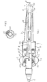
- a coupler 1 is intended for introducing into an open end of a tube pre-installed in a building a lightweight optical element from an installation unit (not shown).
- the installation unit stores lengths of the optical element on reels and includes a feed chamber into which pressurised gas is introduced, the feed chamber having an outlet end from which gas and the optical element emerge.
- the coupler 1 comprises a housing 2 and a tube 4 that extends along the length of the housing, one end of the tube being connected to a flexible hose 6 that is itself connected to the outlet end of the feed chamber of the installation unit and the other end of which ends in the form of a spigot 8.
- a metal sleeve 10 is located around part of the tube 4 so that it ends just short of the spigot 8, and extends approximately half way along the length of the tube.
- the end of the sleeve 10 is coupled to each of a pair of triggers 12 and 14 by means of an articulated coupling arrangement comprising a bent arm 16 that supports a trigger and a coupling rod 18 connected between the bent arm 16 and the sleeve 10.
- Each bent arm 16 is pivotally supported at its elbow 20 and a spring 22 biases the triggers outwardly from the centre of the device, the arrangement being such that manual squeezing of the triggers toward one another wi cause the bent arms 16 to rock about their pivotal elbows and urge the sleeve 10 axially toward the spigot 8 by means of the coupling rods 18.
- a plastics plunger 24 has a bore extending therethrough and is located about the tube 4 and sleeve 10 with the tube and sleeve extending through its bore so that one end 26 of the plunger terminates at the spigot 8 in the region of the end of the sleeve 10.
- the plunger 24 is slidable over the sleeve 10 in a direction away from the spigot 8, but is biased toward the spigot 8 by means of a helical spring (not shown) also disposed around the sleeve 10.
- a safety switch 28 is actuated by axial movement of the plunger 24.
- a further switch (not shown) is actuated by one of the triggers and can override the safety switch 28.
- a pair of dump valves 30 communicate with the bore of the tube 4 and are activated by solenoids 32 controlled by signals from the installation unit so that the gas pressure within the tube can be released if desired.
- the flexible hose 6 that connects the device 1 to the installation unit is shown schematically in cross- section in figure 2 and comprises a central flexible tube 34 formed for example from conductive carbon filled plastics material, a plurality of insulated electrical wires 36 that are helically wrapped around the tube and connect the switches and solenoids in the device to the installation unit, and an outer protective sheath 38 for example in the form of a jacket that has been heat shrunk onto the tube and wires.
- the spigot 8 of the device 1 is inserted into an appropriate connecting device (not shown) positioned on the end of the tube to form a spigot and socket connection.
- an appropriate connecting device (not shown) positioned on the end of the tube to form a spigot and socket connection.
- the connecting device is pushed over the spigot 8 it pushes the plunger 24 in a direction away from the spigot 8 against the bias of its associated spring and actuates the safety switch 28. Only once the safety switch 28 has been actuated can the installation unit close the solenoid operated dump values 30 and cause the fibre or fibre to be introduced into the tube via the flexible hose 6 and device 1 under the flow of gas.
- the triggers 12 and 14 of the device 1 are squeezed and the device is pulled away from the tube.
- the effect of squeezing of the triggers 12 and 14 is to push the sleeve 10 toward the spigot 8 and thereby ease the spigot from the connecting device, and also actuate an override switch that overrides the safety switch 28 and allows the installation unit to supply a further length of optical fibre under reduced gas pressure.
- pressure on the triggers is released and the device 1 is ready to be used to introduce a further quantity of fibre.
- the invention also provides such a device without the safety switch 28.
Landscapes
- Physics & Mathematics (AREA)
- General Physics & Mathematics (AREA)
- Optics & Photonics (AREA)
- Engineering & Computer Science (AREA)
- Civil Engineering (AREA)
- Structural Engineering (AREA)
- Rigid Pipes And Flexible Pipes (AREA)
- Light Guides In General And Applications Therefor (AREA)
Applications Claiming Priority (2)
| Application Number | Priority Date | Filing Date | Title |
|---|---|---|---|
| GB929222842A GB9222842D0 (en) | 1992-10-31 | 1992-10-31 | Apparatus for use in the assembly of an optical fibre transmission line |
| GB9222842 | 1992-10-31 |
Publications (1)
| Publication Number | Publication Date |
|---|---|
| EP0606711A1 true EP0606711A1 (de) | 1994-07-20 |
Family
ID=10724332
Family Applications (1)
| Application Number | Title | Priority Date | Filing Date |
|---|---|---|---|
| EP93308696A Withdrawn EP0606711A1 (de) | 1992-10-31 | 1993-11-01 | Installationsgerät für eine optische Nachrichtenstrecke |
Country Status (2)
| Country | Link |
|---|---|
| EP (1) | EP0606711A1 (de) |
| GB (1) | GB9222842D0 (de) |
Cited By (3)
| Publication number | Priority date | Publication date | Assignee | Title |
|---|---|---|---|---|
| WO1996002012A1 (en) * | 1994-07-08 | 1996-01-25 | British Telecommunications Public Limited Company | Transmission line installation |
| WO1997004344A1 (en) * | 1995-07-24 | 1997-02-06 | Koninklijke Ptt Nederland N.V. | Method and device for installing cables |
| US6129341A (en) * | 1995-07-24 | 2000-10-10 | Koninklijke Ptt Nederland N.V. | Device for installing cables |
Citations (6)
| Publication number | Priority date | Publication date | Assignee | Title |
|---|---|---|---|---|
| US3689031A (en) * | 1971-01-14 | 1972-09-05 | Jet Line Products Inc | Apparatus for installing pull lines in conduits |
| EP0277029A2 (de) * | 1987-01-29 | 1988-08-03 | The Commonwealth Industrial Gases Limited | Pneumatische Pistole |
| EP0384201A2 (de) * | 1989-02-20 | 1990-08-29 | Siemens Aktiengesellschaft | Verfahren zum Einschiessen von Kabeln in ein Rohr |
| EP0457986A1 (de) * | 1990-05-18 | 1991-11-27 | Horii Kiyoshi | Verfahren zum Einführen eines langgestreckten flexiblen Körpers in eine Durchführung |
| EP0463749A2 (de) * | 1990-06-04 | 1992-01-02 | BICC Public Limited Company | Ansclusssystemfür Lichtwellenleiter |
| EP0544388A1 (de) * | 1991-11-28 | 1993-06-02 | Horii, Kiyoshi | Vorrichtung zur Installation eines Drahtes |
-
1992
- 1992-10-31 GB GB929222842A patent/GB9222842D0/en active Pending
-
1993
- 1993-11-01 EP EP93308696A patent/EP0606711A1/de not_active Withdrawn
Patent Citations (6)
| Publication number | Priority date | Publication date | Assignee | Title |
|---|---|---|---|---|
| US3689031A (en) * | 1971-01-14 | 1972-09-05 | Jet Line Products Inc | Apparatus for installing pull lines in conduits |
| EP0277029A2 (de) * | 1987-01-29 | 1988-08-03 | The Commonwealth Industrial Gases Limited | Pneumatische Pistole |
| EP0384201A2 (de) * | 1989-02-20 | 1990-08-29 | Siemens Aktiengesellschaft | Verfahren zum Einschiessen von Kabeln in ein Rohr |
| EP0457986A1 (de) * | 1990-05-18 | 1991-11-27 | Horii Kiyoshi | Verfahren zum Einführen eines langgestreckten flexiblen Körpers in eine Durchführung |
| EP0463749A2 (de) * | 1990-06-04 | 1992-01-02 | BICC Public Limited Company | Ansclusssystemfür Lichtwellenleiter |
| EP0544388A1 (de) * | 1991-11-28 | 1993-06-02 | Horii, Kiyoshi | Vorrichtung zur Installation eines Drahtes |
Cited By (5)
| Publication number | Priority date | Publication date | Assignee | Title |
|---|---|---|---|---|
| WO1996002012A1 (en) * | 1994-07-08 | 1996-01-25 | British Telecommunications Public Limited Company | Transmission line installation |
| US5885027A (en) * | 1994-07-08 | 1999-03-23 | British Telecommunications Public Limited Company | Transmission line installation |
| WO1997004344A1 (en) * | 1995-07-24 | 1997-02-06 | Koninklijke Ptt Nederland N.V. | Method and device for installing cables |
| EA000260B1 (ru) * | 1995-07-24 | 1999-02-25 | Конинклийке ПТТ Недерланд Н.В. | Способ и устройство для прокладки кабелей |
| US6129341A (en) * | 1995-07-24 | 2000-10-10 | Koninklijke Ptt Nederland N.V. | Device for installing cables |
Also Published As
| Publication number | Publication date |
|---|---|
| GB9222842D0 (en) | 1992-12-16 |
Similar Documents
| Publication | Publication Date | Title |
|---|---|---|
| US4731518A (en) | Gun and cable for gas metal arc welding | |
| US4569420A (en) | Lubricating method and system for use in cable pulling | |
| EP1572409B1 (de) | Eine plasmalichtbogenbrennerkabelverlängerung und ein verfahren zum verbinden einer solchen verlängerung mit einer leistungsquelle | |
| US4736978A (en) | Coupling device for inserting cables into cable-protecting pipes | |
| US5457288A (en) | Dual push-cable for pipe inspection | |
| US3547406A (en) | Method and apparatus for running a line through a conduit | |
| KR101521652B1 (ko) | 2개의 아이템을 하나의 관로에 동시에 도입하는 장치 | |
| US5123075A (en) | Overhead electric and optical transmission systems | |
| CA2386210A1 (en) | Connections and terminations for cables | |
| JPS59104607A (ja) | 光フアイバケ−ブルの布設方法および装置 | |
| US8590148B2 (en) | Conduit assembly methods | |
| EP2002297A1 (de) | Kabelinstallation | |
| AU629964B2 (en) | Electric cable installation | |
| US6328583B2 (en) | Re-connectable pipeline connection for direct heating system | |
| US5395091A (en) | Tool and method for installing a cable | |
| NO20161338A1 (en) | Methods for Injecting or Retrieving Tubewire When Connecting Two Strings of Coiled Tubing | |
| JPH0774849B2 (ja) | 線材の布設・回収装置および布設・回収方法 | |
| US20110017335A1 (en) | System for controlling elongation of a conduit within which flowable material is conveyed | |
| US7449661B1 (en) | In-pipe heat trace system | |
| US3899046A (en) | Coupling electric line inside of fluid conduit | |
| US4419534A (en) | End cap for communications cables | |
| CA1051793A (en) | Composite paint hose | |
| EP2576332B1 (de) | Installation zum transport einer flüssigkeit zwischen zwei schiffen | |
| CA2039924C (en) | Composite electric and optical cable manufacture | |
| US12421689B2 (en) | Non-conductive hydro-excavation wands incorporating wear sleeves |
Legal Events
| Date | Code | Title | Description |
|---|---|---|---|
| PUAI | Public reference made under article 153(3) epc to a published international application that has entered the european phase |
Free format text: ORIGINAL CODE: 0009012 |
|
| AK | Designated contracting states |
Kind code of ref document: A1 Designated state(s): DE ES FR GB IT |
|
| 18D | Application deemed to be withdrawn |
Effective date: 19950121 |