EP0606839B1 - Procédé et dispositif pour le formage optique de résine photodurcissable - Google Patents
Procédé et dispositif pour le formage optique de résine photodurcissable Download PDFInfo
- Publication number
- EP0606839B1 EP0606839B1 EP94100061A EP94100061A EP0606839B1 EP 0606839 B1 EP0606839 B1 EP 0606839B1 EP 94100061 A EP94100061 A EP 94100061A EP 94100061 A EP94100061 A EP 94100061A EP 0606839 B1 EP0606839 B1 EP 0606839B1
- Authority
- EP
- European Patent Office
- Prior art keywords
- contour line
- scanning
- scanned
- distance
- radiation beam
- Prior art date
- Legal status (The legal status is an assumption and is not a legal conclusion. Google has not performed a legal analysis and makes no representation as to the accuracy of the status listed.)
- Expired - Lifetime
Links
Images





Classifications
-
- B—PERFORMING OPERATIONS; TRANSPORTING
- B29—WORKING OF PLASTICS; WORKING OF SUBSTANCES IN A PLASTIC STATE IN GENERAL
- B29C—SHAPING OR JOINING OF PLASTICS; SHAPING OF MATERIAL IN A PLASTIC STATE, NOT OTHERWISE PROVIDED FOR; AFTER-TREATMENT OF THE SHAPED PRODUCTS, e.g. REPAIRING
- B29C64/00—Additive manufacturing, i.e. manufacturing of three-dimensional [3D] objects by additive deposition, additive agglomeration or additive layering, e.g. by 3D printing, stereolithography or selective laser sintering
- B29C64/10—Processes of additive manufacturing
- B29C64/106—Processes of additive manufacturing using only liquids or viscous materials, e.g. depositing a continuous bead of viscous material
- B29C64/124—Processes of additive manufacturing using only liquids or viscous materials, e.g. depositing a continuous bead of viscous material using layers of liquid which are selectively solidified
- B29C64/129—Processes of additive manufacturing using only liquids or viscous materials, e.g. depositing a continuous bead of viscous material using layers of liquid which are selectively solidified characterised by the energy source therefor, e.g. by global irradiation combined with a mask
- B29C64/135—Processes of additive manufacturing using only liquids or viscous materials, e.g. depositing a continuous bead of viscous material using layers of liquid which are selectively solidified characterised by the energy source therefor, e.g. by global irradiation combined with a mask the energy source being concentrated, e.g. scanning lasers or focused light sources
-
- B—PERFORMING OPERATIONS; TRANSPORTING
- B29—WORKING OF PLASTICS; WORKING OF SUBSTANCES IN A PLASTIC STATE IN GENERAL
- B29C—SHAPING OR JOINING OF PLASTICS; SHAPING OF MATERIAL IN A PLASTIC STATE, NOT OTHERWISE PROVIDED FOR; AFTER-TREATMENT OF THE SHAPED PRODUCTS, e.g. REPAIRING
- B29C64/00—Additive manufacturing, i.e. manufacturing of three-dimensional [3D] objects by additive deposition, additive agglomeration or additive layering, e.g. by 3D printing, stereolithography or selective laser sintering
- B29C64/30—Auxiliary operations or equipment
- B29C64/386—Data acquisition or data processing for additive manufacturing
- B29C64/393—Data acquisition or data processing for additive manufacturing for controlling or regulating additive manufacturing processes
-
- B—PERFORMING OPERATIONS; TRANSPORTING
- B33—ADDITIVE MANUFACTURING TECHNOLOGY
- B33Y—ADDITIVE MANUFACTURING, i.e. MANUFACTURING OF THREE-DIMENSIONAL [3D] OBJECTS BY ADDITIVE DEPOSITION, ADDITIVE AGGLOMERATION OR ADDITIVE LAYERING, e.g. BY 3D PRINTING, STEREOLITHOGRAPHY OR SELECTIVE LASER SINTERING
- B33Y10/00—Processes of additive manufacturing
-
- B—PERFORMING OPERATIONS; TRANSPORTING
- B33—ADDITIVE MANUFACTURING TECHNOLOGY
- B33Y—ADDITIVE MANUFACTURING, i.e. MANUFACTURING OF THREE-DIMENSIONAL [3D] OBJECTS BY ADDITIVE DEPOSITION, ADDITIVE AGGLOMERATION OR ADDITIVE LAYERING, e.g. BY 3D PRINTING, STEREOLITHOGRAPHY OR SELECTIVE LASER SINTERING
- B33Y50/00—Data acquisition or data processing for additive manufacturing
- B33Y50/02—Data acquisition or data processing for additive manufacturing for controlling or regulating additive manufacturing processes
Definitions
- the present invention relates to a method of and an apparatus for optically shaping a photo-setting resin into a three-dimensional resin model according to the precharacterising parts of claims 1 and 5 respectively.
- an ultra-violet laser beam is generated by an ultraviolet laser oscillator, turned on and off and scanned under the control of an optical system which has a galvanometer mirror and a shutter, and applied to the surface of an ultraviolet-curing resin solution stored in a tank.
- the tank accommodates therein a vertically movable elevator which can block the ultraviolet laser beam.
- a resin solution layer that is interposed between the surface of the ultraviolet-curing resin solution and the elevator is set by the ultraviolet laser beam applied thereto.
- the elevator In the optical shaping process, the elevator is in a lifted position, and a resin solution layer that is present between the surface of the ultraviolet-curing resin solution and the elevator is set by the ultraviolet laser beam applied thereto, thereby forming a first scanned set layer. Then, the elevator is lowered a distance corresponding to the first scanned set layer, and the scanning ultraviolet laser beam is applied to form a second scanned set layer over the first scanned set layer. Subsequently, scanned set layers are successively formed downwardly until a final scanned set layer is formed. After the final scanned set layer is formed, the elevator is lifted to remove a desired resin model, which is composed of the stack of scanned set layers thus produced, out of the resin solution. To finally set the resin model, the resin model, designated by W in FIG. 10 of the accompanying drawings, is irradiated with an ultraviolet radiation emitted from an ultraviolet lamp 50 for a long period of time.
- a horizontal plane in the ultraviolet-curing resin solution within each vertical distance that the elevator traverses on its vertical movement is hereinafter referred to as an isometric section.
- One isometric section contains a region (set region) where the resin solution is to be set and a region (unset region) where the resin solution is not to be set, depending on the three-dimensional shape of the resin model W to be fabricated.
- the ultraviolet laser beam generated by the ultra-violet laser oscillator is scanned along a scanning line over the resin solution layer in each isometric section by the optical system.
- the ultraviolet laser beam is turned on, i.e., a shutter (AOM) is open, within the set region, and is turned off, i.e., the shutter (AOM) is closed, within the unset region.
- AOM shutter
- the ultraviolet laser beam is shifted a scanning pitch, and then scanned along a next scanning line over the resin solution layer.
- the ultraviolet laser beam When the ultraviolet laser beam is applied to the ultraviolet-curing resin solution, the radiation energy thereof is progressively reduced as it enters the ultraviolet-curing resin solution. Therefore, from a microscopic viewpoint, the region of the ultraviolet-curing resin solution which is irradiated with the ultraviolet laser beam, i.e., the scanned set layer, contains sharp lower edges of set resin.
- an upper scanned set layer is produced by an ultraviolet laser beam whose radiation energy is strong enough to irradiate a lower resin solution layer, so that the depth to which the resin solution is set across the upper-layer isometric section is larger than the actual thickness of the upper scanned set layer.
- the successive scanned set layers of ultraviolet-curing resin are joined together with a large bonding strength.
- the scanned set layer in one isometric section is of a closed region enclosed by a contour line as shown in FIG. 11 of the accompanying drawings, then it is formed according to the conventional optical shaping process as follows: First, a contour line OL shown in FIG. 11 is recognized. Then, as shown in FIG. 12 of the accompanying drawings, the resin solution layer is scanned along a scanning line parallel to one edge OL1 of the contour from a start-of-scan point P0 to an end-of-scan point P1. Thereafter, the optical system is controlled to shift the scanning ultraviolet laser beam by a scanning pitch, and then the resin solution layer is scanned along a next scanning line from a start-of-scan point P2.
- Such a scanning mode is referred to as a raster scanning mode.
- the ultraviolet laser beam is applied as a circular beam spot to the ultraviolet-curing resin solution. Therefore, as shown in FIG. 12, the scanned set layer is not shaped exactly along the contour line at edges OL2, OL3 where the scanning lines start and end. Consequently, the conventional optical shaping process suffers problems in the production of highly accurate resin models.
- a method of optically shaping a photo-setting resin into a three-dimensional resin model by scanning successive resin solution layers of a photo-setting resin solution with a radiation beam to form a stack of scanned set layers of photo-setting resin by actuating an elevator means between said layers, each of said successive resin solution layers having a shaped region of an isometric section, the method comprising the steps of a) scanning the radiation beam in a layer along a contour line of the shaped region to set the shaped region along the contour line, and b) scanning the radiation beam in the same layer in a raster scanning mode to set the shaped region inwardly of the contour line, holding the height of said elevator means constant during said scanning step a) and b).
- the radiation beam may be scanned along a line which is spaced a distance r1 inwardly from the contour line.
- the radiation beam may be scanned along a first line which is spaced a first distance inwardly from the contour line thereby to set the shaped region along the first line, and the radiation beam may be scanned inwardly of a second line which is spaced a second distance r2 inwardly from the contour line thereby to set the shaped region inwardly of the second line.
- an apparatus for optically shaping a photo-setting resin into a three-dimensional resin model according to claim 5 is also provided.
- Particular embodiments of the apparatus according to claim 5 are disclosed in the dependent claims 6 and 7.
- the control means comprises means for controlling said optical scanner means to scan the scanned set layer with the radiation beam in a vector scanning mode based on the path information calculated by the contour set information extractor and in a raster scanning mode based on the closed region extracted by the inside region information extractor.
- the first distance may be smaller than the second distance.
- the scanned set layer is scanned based on the extracted contour line information and also scanned based on the extracted closed region. Particularly, the scanned set region is scanned in the vector scanning mode along the contour line, and in the raster scanning mode inwardly of the contour line.
- the vector scanning mode may be carried out before the raster scanning mode, or vice versa.
- the radiation beam is scanned along the line that is spaced the first distance (r1) rinwardly from the contour line.
- the radiation beam is scanned inwardly of the line that is spaced the second distance (r2) inwardly from the contour line.
- the optical scanner means generates a radiation beam including a wavelength suitable for photo-setting the photo-setting resin solution, and applies the radiation beam to scan the photo-setting resin solution stored in the tank.
- a scanned set layer of photo-setting resin produced by exposure to the radiation beam is lowered by the elevator means. Then, the above process is repeated to generate a stack of successive scanned set layers.
- information relative to a scanned set layer to be formed by applying and scanning the radiation beam without moving the elevator means is extracted from the three-dimensional shape information memory by the scanned set layer information extractor.
- the contour line detector Based on the scanned set layer information produced by the scanned set layer information extractor, the contour line detector detects the contour line of the scanned set layer, and the contour set information extractor calculates the line spaced the first distance (r1) inwardly from the contour line as path information.
- the path information is outputted to the optical scanner means, and the vector scanning mode is carried out along the contour line. Since the radiation beam moves along the contour line, the scanned set layer is shaped highly accurately along the contour line without having to reduce the spot diameter of the radiation beam and the scanning pitch.
- the inside region information extractor extracts information relative to the closed region that is spaced the second distance (r2) inwardly from the contour line detected by the contour line detector.
- the extracted information is outputted to the optical scanner means.
- the raster scanning mode is carried out in the closed region enclosed by the contour line.
- any overlap between a scanned set layer produced by the vector scanning mode along the contour line and a scanned set layer produced by the raster scanning mode is minimized. Therefore, when the photo-setting resin solution is set, it shrinks with a relatively uniform shrinkage factor, and the produced resin model is prevented from being unduly deformed.
- the shaped region is set by being scanned with a radiation beam along the contour line of the shaped region, and an inside region inward of the contour line is set by being scanned with the radiation beam in the raster scanning mode.
- the shaped region is formed highly accurately in the isometric region.
- the radiation beam is scanned along the line that is spaced the first distance (r1) inwardly from the contour line in the vector scanning mode to set the shaped region along the contour line, and scanned inwardly of the line that is spaced the second distance (r2) inwardly from the contour line in the raster scanning mode to set the region inwardly of the contour line, then an overlap of the set regions produced by the vector and raster scanning modes is minimized, preventing the resin model from being unduly deformed due to shrinkage upon being set.
- an optical shaping apparatus includes a tank 2 containing a photo-setting resin solution 1 which can be set due to addition polymerization when exposed to light LB.
- a vinyl monomer such as styrene, methyl methacrylate, and vinyl acetate polymerizes even in the absence of a photopolymerization initiator or in the presence of a sensitizer or dye which absorbs ultraviolet radiation.
- the photo-setting resin solution 1 that can be employed in the present invention is not limited to any materials, but may be a resin which can be set into a solid state even if it is of a liquid state when not set.
- the light LB may be an ultraviolet radiation or other light selected depending on the photo-setting resin solution 1.
- the tank 2 accommodates therein an elevator 4a having a table for supporting set resin layers thereon, the table being capable of blocking light against transmission therethrough.
- the elevator 4a can be vertically moved in the tank 2 by a lifter 4b that is positioned outside of the tank 2.
- the lifter 4b can mechanically elevate and lower the elevator 4a and control the vertical movement of the elevator 4a.
- the elevator 4a and the lifter 4b jointly serve as an elevator system 4.
- the lifter 4b is supplied with a command signal from a generator controller 5a of a control system 5.
- the general controller 5a supplies a command signal to the lifter 4b based on information supplied to or from an optical scanning system 3.
- the general controller 5a when the general controller 5a detects the completion of scanning over one isometric section based on information supplied from the optical scanning system 3, the general controller 5a applies a command signal to the lifter 4b to cause the lifter 4b to lower the elevator 4a a distance or pitch that is equal to the thickness T of a scanned set layer that has been formed in the isometric section.
- the optical scanning system 3 comprises a laser oscillator 3a for generating a laser beam such as an ultraviolet laser beam, an optical system 3b for scanning the laser beam generated by the laser oscillator 3a over the surface of the photo-setting resin solution 1 in a predetermined scanning pattern, and an optical system controller 3c for controlling the optical system 3b.
- the optical system 3b includes a shutter (AOM) for selectively passing and blocking the laser beam, and a voltage applicator and a galvanometric mirror for changing the direction of the laser beam, and can turn on and off the laser beam, vary the intensity or radiation energy of the laser beam, change the path or direction of the laser beam, and control the speed at which the laser beam is scanned.
- the optical system controller 3c supplies the optical system 3b with a command signal relative to scanning conditions according to the predetermined scanning pattern.
- the optical scanning system 3 operates essentially based on basic pattern data that been supplied in advance to the general controller 5a. Specific scanning conditions supplied from the optical system controller 3c to the optical system 3b may be modified by command signals that are given from the control system 5 to the optical system controller 3c.
- the general controller 5a of the control system 5 controls the elevator system 4 and the optical scanning system 3 in a mutually related manner based on previously supplied data depending on a resin model to be formed.
- the control system 5 includes, in addition to the general controller 5a, a three-dimensional shape information memory 5b, a scanned set layer information extractor 5c, a contour line detector 5d, a contour set information extractor 5e, and an inside region information extractor 5f.
- the lifter 4b, the optical system controller 3c, and the control system 5 are shown as separate from each other in FIG. 1 for an easier understanding of their functions. However, the lifter 4b, the optical system controller 3c, and the control system 5 may be combined into an information processing system in so far as it has their functions.
- Respective processing sequences of the three-dimensional shape information memory 5b, the scanned set layer information extractor 5c, the contour line detector 5d, the contour set information extractor 5e, and the inside region information extractor 5f will be described below with respect to the formation of a region enclosed by a contour line within an isometric section as shown in FIG. 11 by way of illustrative example.
- the three-dimensional shape information memory 5b stores all information relative to the three-dimensional shape of a resin model W to be formed, or at least information relative to the three-dimensional shapes of all isometric sections where shaped regions are enclosed by contour lines.
- the scanned set layer information extractor 5c extracts only information relative to a scanned set layer which is a shaped region in one isometric section from the three-dimensional information stored in the three-dimensional shape information memory 5b. Specifically, the general controller 5a distinguishes a set region from an unset region in a certain isometric section for the control of the turning-on and -off of the laser beam in the optical system 3b, and the scanned set layer information extractor 5c selects and read only information relative to such a set region.
- the information extracted by the scanned set layer information extractor 5c will be used as basic information in the shaping process described below.
- the contour line detector 5d reads the information relative to the set region extracted by the scanned set layer information extractor 5c, and recognizes a contour line OL of the set region in the isometric section based on the information thus read.
- the contour set information extractor 5e calculates a contour line OLA (see FIG. 2) that is spaced a distance r1 from the contour line OL read by the contour line detector 5d, inwardly within the closed region.
- the calculated contour line OLA will serve as a central line for vector scanning along the contour line as described later on.
- the distance r1 should preferably be equal to the radius of the ultraviolet laser beam LB, more strictly, the radius of a circular spot set by the ultraviolet laser beam LB.
- the inside region information extractor 5f calculates another contour line OLB (see FIG. 2) that is spaced a distance r2 from the contour line OL inwardly within the closed region.
- the calculated contour line OLB will serve as a start-of-scan point, an end-of-scan point, or a central line for raster scanning in the closed region as described later on.
- the distance r2 should preferably be selected such that the contour line OLB is spaced inwardly a distance equal to the radius of the ultraviolet laser beam LB, more strictly, the radius of a circular spot set by the ultraviolet laser beam LB, from the contour line OLA. In this embodiment, the distance r2 is greater than the distance r1.
- the contour line information produced by the contour set information extractor 5e is outputted to the optical system controller 3c.
- the ultraviolet laser beam LB is scanned based on the contour line information produced by the contour set information extractor 5e in a vector scanning mode along the contour line OLA.
- the ultraviolet laser beam LB only traces the contour line OLA, and a start-of-scan point, an end-of-scan point, and a scanning line are not defined for scanning the ultraviolet laser beam LB.
- the information relative to the closed region, produced by the inside region information extractor 5f, is also outputted to the optical system controller 3c.
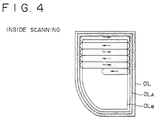
- the ultraviolet laser beam LB is scanned based on the information produced by the inside region information extractor 5f in a raster scanning mode in one or opposite directions along the contour line OLB.
- FIGS. 2 through 5 are illustrative of an optical shaping method according to an embodiment of the present invention.
- the contour line OL is scanned in the vector scanning mode, and the inside re-gion enclosed by the contour line OL is scanned in the raster scanning mode.
- the central line for the vector scanning mode is the contour line OLA that is spaced or offset the distance r1 inwardly from the contour line OL.
- Start-of-scan and end-of-scan points for the raster scanning mode are spaced or offset the distance r2 inwardly from the contour line OL.
- the optical scanning system 3 generates an ultraviolet laser beam LB including a wavelength suitable for setting the photo-setting resin solution 1, and applies the ultraviolet laser beam LB to scan the photo-setting resin solution 1 in the tank 2.
- an ultraviolet laser beam LB including a wavelength suitable for setting the photo-setting resin solution 1
- a scanned set layer 51 of photo-setting resin produced by exposure to the ultraviolet laser beam LB is lowered by the elevator system 4. Then, the above process is repeated to generate a stack of successive scanned set layers 51.
- the above process of producing a scanned set layer 51 of photo-setting resin will be described in detail below.
- information relative to a scanned set layer 51 to be formed by applying and scanning the ultraviolet laser beam LB without moving the elevator 4a is extracted from the three-dimensional shape information memory 5b by the scanned set layer information extractor 5c in a step S1 (see FIG. 5).
- the scanned set layer information extractor 5c reads offset distances r1, r2 in a step S2.
- the contour line detector 5d Based on the scanned set layer information produced by the scanned set layer information extractor 5c, the contour line detector 5d detects the contour line OL of the scanned set layer 51, and the contour set information extractor 5e calculates the contour line OLA spaced the distance r1 inwardly from the contour line OL as path information in a step S3 (see FIG. 2).
- the path information is outputted to the optical system controller 3c in a step S6, and the vector scanning mode is carried out along the contour line OLA in a step S7 (see FIG. 3). Since the ultraviolet laser beam LB moves along the contour line OL, the scanned set layer is shaped highly accurately along the contour line OL without having to reduce the spot diameter of the ultraviolet laser beam LB and the scanning pitch.
- the inside region information extractor 5f extracts information relative to the closed region that is spaced the distance r2 inwardly from the contour line OL detected by the contour line detector 5d in a step S4 (see FIG. 2).
- Span data are generated by calculating intersection between the closed region and scanning lines in a step S5.
- the extracted information is outputted to the optical system controller 3c in a step S8.
- the raster,scanning mode is carried out in the closed region enclosed by the contour line OLB in a step S9 (see FIG. 4).
- the distance r1 is smaller than the distance r2, any overlap between a scanned set layer produced by the vector scanning mode along the contour line and a scanned set layer produced by the raster scanning mode is minimized. Therefore, when the photo-setting resin solution is set, it shrinks with a relatively uniform shrinkage factor, and the produced resin model is prevented from being unduly deformed.
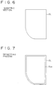
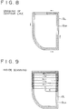
- FIGS. 6 through 9 illustrate an optical shaping method according to another embodiment of the present invention.
- the central line for the vector scanning mode is a contour line OLA that is spaced or offset a distance r1 inwardly from the contour line OL, and start-of-scan and end-of-scan points for the raster scanning mode are defined in relation to the contour line OLA.
- the contour line detector 5d Based on the scanned set layer information produced by the scanned set layer information extractor 5c, the contour line detector 5d detects the contour line OL of the scanned set layer 51, and the contour set information extractor 5e calculates the contour line OLA spaced the distance r1 from the contour line OL as path information (see FIG. 7).
- the path information is outputted to the optical system controller 3c, and the vector scanning mode is carried out along the contour line OLA in the same manner as with the preceding embodiment (see FIG. 8). Since the ultraviolet laser beam LB moves along the contour line OL, the scanned set layer is shaped highly accurately along the contour line OL without having to reduce the spot diameter of the ultraviolet laser beam LB and the scanning pitch.
- the raster scanning mode is carried out in the closed region enclosed by the contour line OLA (see FIG. 9).
- a scanned set layer produced by the vector scanning mode along the contour line and a scanned set layer produced by the raster scanning mode partly overlap each other. If the shrinkage factor of the photo-setting resin is small, then any deformation of the produced resin model upon being set is not problematic, and hence the time required to calculate the contour line OLA is reduced.
- the offset distances r1, r2 from the contour line OL are not limited to the magnitudes in the illustrated embodiments, and the contour lines OLA, OLB may be offset by distances which vary in different positions.
Landscapes
- Chemical & Material Sciences (AREA)
- Engineering & Computer Science (AREA)
- Materials Engineering (AREA)
- Physics & Mathematics (AREA)
- Optics & Photonics (AREA)
- Manufacturing & Machinery (AREA)
- Mechanical Engineering (AREA)
- Heating, Cooling, Or Curing Plastics Or The Like In General (AREA)
- Exposure And Positioning Against Photoresist Photosensitive Materials (AREA)
Claims (7)
- Procédé de formage optique d'une résine photodurcissable en un modèle de résine tridimensionnel en balayant des couches de solutions de résine successives d'une solution de résine photodurcissable (1) à l'aide d'un faisceau de rayonnement pour former une superposition de couches durcies balayées de résine photodurcissable en actionnant un moyen élévateur (4) entre lesdites couches, chacune desdites couches de solution de résine successives possédant une région formée d'une section isométrique, ledit procédé étant caractérisé par les étapes consistant à:a) déplacer le faisceau de rayonnement dans une couche le long d'une ligne de contour (OL) de la région formée pour durcir la région formée le long de ladite ligne de contour (OL),b) déplacer le faisceau de rayonnement dans la même couche selon un mode de balayage plus rapide pour durcir la région formée à l'intérieur de ladite ligne de contour (OL), en maintenant la hauteur dudit élévateur constante durant lesdites étapes de balayage a) et b).
- Procédé selon la revendication 1, dans lequel ladite étape de balayage a) comporte l'étape de déplacement du faisceau de rayonnement le long d'une ligne (OLA) qui est espacée d'une distance (rl) à l'intérieur de ladite ligne de contour (OL).
- Procédé selon la revendication 1, dans lequel ladite étape de balayage a) comporte l'étape consistant à déplacer le faisceau de rayonnement selon une première ligne (OLA) qui est espacée d'une première distance (r1) à l'intérieur de ladite ligne de contour (OL) pour ainsi durcir la région formée selon ladite première ligne (OLA), et ladite étape de balayage b) comporte en outre l'étape consistant à déplacer le faisceau de rayonnement à l'intérieur d'une seconde ligne (OLB) qui est espacée d'une seconde distance (r2) à l'intérieur de ladite ligne de contour (OL) pour ainsi durcir la région formée à l'intérieur de ladite seconde ligne (OLB).
- Procédé selon la revendication 3, dans lequel ladite première distance (r1) est plus courte que ladite seconde distance (r2).
- Dispositif de formage optique d'une résine photodurcissable en un modèle de résine tridimensionnel, comportant :un réservoir (2) contenant une solution de résine photodurcissable (1);des moyens de balayage optique (3) pour générer et déplacer un faisceau de rayonnement comprenant une longueur d'onde appropriée pour un photodurcissement de ladite solution de résine photodurcissable (1) au-dessus de la solution de résine photodurcissable (1) pour produire une couche durcie balayée à l'intérieur;un moyen élévateur (4a, 4b) pour déplacer verticalement la couche durcie balayée produite lorsque ladite solution de résine photodurcissable (1) est balayée par ledit faisceau de rayonnement; etdes moyens de commande (5) pour commander lesdits moyens de balayage optique (3) et ledit élévateur (4a, 4b);lesdits moyens de commande (5) comportant :une mémoire d'information de forme tridimensionle (5b) pour mémoriser au moins une partie de l'information de forme tridimensionnelle du modèle de résine tridimensionnel devant être formé;un extracteur d'information de couche durcie balayée (5c) pour extraire une information concernant une couche durcie balayée qui doit être formée par le faisceau de rayonnement, à partir de l'information de forme tridimensionnelle mémorisée dans ladite mémoire d'information de forme tridimensionnelle (5b);un détecteur de ligne de contour (5d) pour détecter une ligne de contour de la région durcie balayée en fonction de l'information extraite par ledit extracteur d'information de couche durcie balayée (5c),caractérisé par un extracteur d'information de détermination de contour (5e) pour calculer, en tant qu'information de trajet, une ligne qui est espacée d'une première distance (r1) à l'intérieur de ladite ligne de contour (OL) détectée par ledit détecteur de ligne de contour (5d);un extracteur d'information de région intérieure (5f) pour extraire une région fermée à l'intérieur d'une ligne qui est espacée d'une seconde distance (r2) à l'intérieur de ladite ligne de contour (OL) détectée par ledit détecteur de ligne de contour (5d), de telle sorte que les moyens de commande (5) pour commander lesdits moyens de balayage optique (3) sont prévus pour balayer la couche durcie balayée avec le faisceau de rayonnement en fonction de l'information de trajet calculée par ledit extracteur d'information déterminé de contour (5e) et la région fermée extraite par ledit extracteur d'information de région intérieure (5f),en maintenant la hauteur dudit élévateur (4a, 4b) constante durant ledit balayage de la ligne de contour (OL) et de la région fermée de ladite couche.
- Dispositif selon la revendication 5, dans lequel ledit moyen de commande (5) comportent des moyens pour commander lesdits moyens de balayage optique (3) pour balayer la couche durcie balayée avec le faisceau de rayonnement selon un mode de balayage vectoriel en fonction de l'information de trajet calculée par ledit extracteur d'information déterminée de contour (5e) et selon un mode de balayage en réseau en fonction de la région fermée extraite par ledit extracteur d'information de région intérieure (5f).
- Dispositif selon la revendication 5, dans lequel ladite première distance (r1) est inférieure à ladite seconde distance (r2).
Applications Claiming Priority (2)
| Application Number | Priority Date | Filing Date | Title |
|---|---|---|---|
| JP5003203A JP2853497B2 (ja) | 1993-01-12 | 1993-01-12 | 光学的造形装置 |
| JP3203/93 | 1993-01-12 |
Publications (2)
| Publication Number | Publication Date |
|---|---|
| EP0606839A1 EP0606839A1 (fr) | 1994-07-20 |
| EP0606839B1 true EP0606839B1 (fr) | 1997-04-02 |
Family
ID=11550884
Family Applications (1)
| Application Number | Title | Priority Date | Filing Date |
|---|---|---|---|
| EP94100061A Expired - Lifetime EP0606839B1 (fr) | 1993-01-12 | 1994-01-04 | Procédé et dispositif pour le formage optique de résine photodurcissable |
Country Status (5)
| Country | Link |
|---|---|
| US (2) | US5496683A (fr) |
| EP (1) | EP0606839B1 (fr) |
| JP (1) | JP2853497B2 (fr) |
| KR (2) | KR100277397B1 (fr) |
| DE (1) | DE69402331T2 (fr) |
Families Citing this family (19)
| Publication number | Priority date | Publication date | Assignee | Title |
|---|---|---|---|---|
| DE4309524C2 (de) * | 1993-03-24 | 1998-05-20 | Eos Electro Optical Syst | Verfahren zum Herstellen eines dreidimensionalen Objekts |
| JP3431387B2 (ja) * | 1996-03-14 | 2003-07-28 | 株式会社東芝 | 露光強度分布表示方法とマスクパターン編集装置 |
| US5979606A (en) * | 1997-12-23 | 1999-11-09 | Sony Corporation | Conveyor elevator |
| DE10165115B3 (de) * | 2000-03-15 | 2017-10-12 | Realizer Gmbh | Verfahren und Vorrichtung zur Herstellung eines Formkörpers |
| US6730256B1 (en) | 2000-08-04 | 2004-05-04 | Massachusetts Institute Of Technology | Stereolithographic patterning with interlayer surface modifications |
| US6833234B1 (en) * | 2000-08-04 | 2004-12-21 | Massachusetts Institute Of Technology | Stereolithographic patterning with variable size exposure areas |
| US6777170B1 (en) * | 2000-08-04 | 2004-08-17 | Massachusetts Institute Of Technology | Stereolithographic patterning by variable dose light delivery |
| US6699424B2 (en) * | 2001-06-29 | 2004-03-02 | 3D Systems, Inc. | Method for forming three-dimensional objects |
| US7261542B2 (en) * | 2004-03-18 | 2007-08-28 | Desktop Factory, Inc. | Apparatus for three dimensional printing using image layers |
| US7862886B2 (en) * | 2005-08-12 | 2011-01-04 | Fujifilm Corporation | Optical film, antireflection film, processes for producing the same, and polarizing plate and display employing the same |
| GB201016169D0 (en) * | 2010-09-27 | 2010-11-10 | Materialise Nv | Method for reducing differential shrinkage in stereolithography |
| JP5993224B2 (ja) * | 2012-06-18 | 2016-09-14 | ローランドディー.ジー.株式会社 | 三次元造形装置 |
| FR2992877B1 (fr) * | 2012-07-06 | 2015-07-03 | Phenix Systems | Procede de pilotage de faisceau laser pour fabrication d'objets tridimensionnels par couches superposees. |
| FR2994885B1 (fr) * | 2012-08-29 | 2014-08-29 | Carpyz | Machines pour la fabrication de produits circulaires par addition couche par couche |
| CN105163929B (zh) * | 2013-05-03 | 2017-05-10 | 联合工艺公司 | 消除次表面孔隙度的方法 |
| JP6030597B2 (ja) * | 2014-04-04 | 2016-11-24 | 株式会社松浦機械製作所 | 三次元造形装置及び三次元形状造形物の製造方法 |
| DE102017110241A1 (de) * | 2017-05-11 | 2018-11-15 | Nanoscribe Gmbh | Verfahren zum Erzeugen einer 3D-Struktur mittels Laserlithographie sowie Computerprogrammprodukt |
| US10518356B2 (en) | 2018-02-05 | 2019-12-31 | General Electric Company | Methods and apparatus for generating additive manufacturing scan paths using thermal and strain modeling |
| WO2023278880A2 (fr) * | 2021-07-02 | 2023-01-05 | Stratasys, Inc | Procédé de régulation de tolérances dimensionnelles, de qualité de surface et de temps d'impression concernant des pièces imprimées en 3d |
Family Cites Families (9)
| Publication number | Priority date | Publication date | Assignee | Title |
|---|---|---|---|---|
| ATE113746T1 (de) * | 1986-06-03 | 1994-11-15 | Cubital Ltd | Gerät zur entwicklung dreidimensionaler modelle. |
| US5059359A (en) * | 1988-04-18 | 1991-10-22 | 3 D Systems, Inc. | Methods and apparatus for production of three-dimensional objects by stereolithography |
| JP2715527B2 (ja) * | 1989-03-14 | 1998-02-18 | ソニー株式会社 | 立体形状形成方法 |
| JPH0624773B2 (ja) * | 1989-07-07 | 1994-04-06 | 三井造船株式会社 | 光学的造形法 |
| US5071337A (en) * | 1990-02-15 | 1991-12-10 | Quadrax Corporation | Apparatus for forming a solid three-dimensional article from a liquid medium |
| JPH0773884B2 (ja) * | 1990-05-02 | 1995-08-09 | 三菱商事株式会社 | 光固化造形装置 |
| JPH0745196B2 (ja) * | 1990-11-02 | 1995-05-17 | 三菱商事株式会社 | 光固化造形装置 |
| US5460758A (en) * | 1990-12-21 | 1995-10-24 | Eos Gmbh Electro Optical Systems | Method and apparatus for production of a three-dimensional object |
| JPH06114948A (ja) * | 1992-10-01 | 1994-04-26 | Shiimetsuto Kk | 未硬化液排出口付光硬化造形物とその造形法 |
-
1993
- 1993-01-12 JP JP5003203A patent/JP2853497B2/ja not_active Expired - Lifetime
-
1994
- 1994-01-03 KR KR1019940000006A patent/KR100277397B1/ko not_active Expired - Lifetime
- 1994-01-04 DE DE69402331T patent/DE69402331T2/de not_active Expired - Lifetime
- 1994-01-04 EP EP94100061A patent/EP0606839B1/fr not_active Expired - Lifetime
- 1994-01-12 US US08/180,318 patent/US5496683A/en not_active Expired - Lifetime
-
1995
- 1995-06-07 US US08/475,764 patent/US5562929A/en not_active Expired - Lifetime
-
1998
- 1998-11-04 KR KR1019980047078A patent/KR100308894B1/ko not_active Expired - Lifetime
Also Published As
| Publication number | Publication date |
|---|---|
| US5562929A (en) | 1996-10-08 |
| KR100277397B1 (ko) | 2001-01-15 |
| KR940018189A (ko) | 1994-08-16 |
| US5496683A (en) | 1996-03-05 |
| EP0606839A1 (fr) | 1994-07-20 |
| KR100308894B1 (ko) | 2002-09-27 |
| DE69402331T2 (de) | 1997-11-06 |
| JP2853497B2 (ja) | 1999-02-03 |
| DE69402331D1 (de) | 1997-05-07 |
| JPH06206260A (ja) | 1994-07-26 |
Similar Documents
| Publication | Publication Date | Title |
|---|---|---|
| US5496683A (en) | Method of and apparatus for optically shaping photo-setting resin | |
| EP0388129B2 (fr) | Procédé et dispositif pour fabriquer des objets tridimensionnels | |
| KR0178873B1 (ko) | 스테레오리소그래픽 커얼 감소 | |
| JP2000000893A (ja) | 三次元物体を形成する方法および装置 | |
| JPS61114818A (ja) | 立体形状形成装置 | |
| JP2676838B2 (ja) | 立体像形成方法 | |
| EP0609772A1 (fr) | Procédé et dispositif pour le formage optique d'une résine photodurcissable | |
| JPH02178022A (ja) | 立体形状形成装置 | |
| JP3779358B2 (ja) | 立体形状造形方法 | |
| JP3252859B2 (ja) | 立体形状成形装置および立体形状成形方法 | |
| WO1990011178A1 (fr) | Procede de production d'une forme tridimensionnelle | |
| JP3653385B2 (ja) | 光学的造形方法 | |
| JPS61217219A (ja) | 立体形状形成装置 | |
| JP2000043148A (ja) | 光造形方法及びその装置 | |
| JPS61116320A (ja) | 立体形状形成装置 | |
| JPS63145016A (ja) | 立体形状形成装置 | |
| JP3173212B2 (ja) | 光学的造形方法および光学的造形装置 | |
| JP3173196B2 (ja) | 光学的造形方法および光学的造形装置 | |
| JPH06270265A (ja) | 光学的造形方法および光学的造形装置 | |
| JPH02303817A (ja) | 立体形状形成装置 | |
| JP3170832B2 (ja) | 光学的造形方法 | |
| JP3458437B2 (ja) | 光学的造形方法および光学的造形装置 | |
| RU2145924C1 (ru) | Полимерный трехмерный объект сложной формы, составленный из слоев, способ изготовления полимерного трехмерного объекта и устройство для его осуществления | |
| JPH07171898A (ja) | 三次元形状の形成方法 | |
| JPH10128856A (ja) | 光造形データ処理法およびその装置 |
Legal Events
| Date | Code | Title | Description |
|---|---|---|---|
| PUAI | Public reference made under article 153(3) epc to a published international application that has entered the european phase |
Free format text: ORIGINAL CODE: 0009012 |
|
| AK | Designated contracting states |
Kind code of ref document: A1 Designated state(s): DE GB |
|
| 17P | Request for examination filed |
Effective date: 19941219 |
|
| 17Q | First examination report despatched |
Effective date: 19951113 |
|
| GRAG | Despatch of communication of intention to grant |
Free format text: ORIGINAL CODE: EPIDOS AGRA |
|
| GRAH | Despatch of communication of intention to grant a patent |
Free format text: ORIGINAL CODE: EPIDOS IGRA |
|
| GRAH | Despatch of communication of intention to grant a patent |
Free format text: ORIGINAL CODE: EPIDOS IGRA |
|
| GRAA | (expected) grant |
Free format text: ORIGINAL CODE: 0009210 |
|
| RAP1 | Party data changed (applicant data changed or rights of an application transferred) |
Owner name: SONY CORPORATION |
|
| AK | Designated contracting states |
Kind code of ref document: B1 Designated state(s): DE GB |
|
| REF | Corresponds to: |
Ref document number: 69402331 Country of ref document: DE Date of ref document: 19970507 |
|
| PLBE | No opposition filed within time limit |
Free format text: ORIGINAL CODE: 0009261 |
|
| STAA | Information on the status of an ep patent application or granted ep patent |
Free format text: STATUS: NO OPPOSITION FILED WITHIN TIME LIMIT |
|
| 26N | No opposition filed | ||
| REG | Reference to a national code |
Ref country code: GB Ref legal event code: IF02 |
|
| REG | Reference to a national code |
Ref country code: GB Ref legal event code: 746 Effective date: 20120703 |
|
| REG | Reference to a national code |
Ref country code: DE Ref legal event code: R084 Ref document number: 69402331 Country of ref document: DE Effective date: 20120614 |
|
| PGFP | Annual fee paid to national office [announced via postgrant information from national office to epo] |
Ref country code: DE Payment date: 20130122 Year of fee payment: 20 Ref country code: GB Payment date: 20130122 Year of fee payment: 20 |
|
| REG | Reference to a national code |
Ref country code: DE Ref legal event code: R071 Ref document number: 69402331 Country of ref document: DE |
|
| REG | Reference to a national code |
Ref country code: GB Ref legal event code: PE20 Expiry date: 20140103 |
|
| PG25 | Lapsed in a contracting state [announced via postgrant information from national office to epo] |
Ref country code: GB Free format text: LAPSE BECAUSE OF EXPIRATION OF PROTECTION Effective date: 20140103 Ref country code: DE Free format text: LAPSE BECAUSE OF EXPIRATION OF PROTECTION Effective date: 20140108 |