EP0606861A1 - Dispositif d'encrage pour une machine à imprimer rotative - Google Patents
Dispositif d'encrage pour une machine à imprimer rotative Download PDFInfo
- Publication number
- EP0606861A1 EP0606861A1 EP94100210A EP94100210A EP0606861A1 EP 0606861 A1 EP0606861 A1 EP 0606861A1 EP 94100210 A EP94100210 A EP 94100210A EP 94100210 A EP94100210 A EP 94100210A EP 0606861 A1 EP0606861 A1 EP 0606861A1
- Authority
- EP
- European Patent Office
- Prior art keywords
- ink
- cylinder
- roller
- inking
- width
- Prior art date
- Legal status (The legal status is an assumption and is not a legal conclusion. Google has not performed a legal analysis and makes no representation as to the accuracy of the status listed.)
- Granted
Links
- 239000000976 ink Substances 0.000 claims description 73
- 230000005540 biological transmission Effects 0.000 claims 1
- 238000010586 diagram Methods 0.000 description 4
- 239000003086 colorant Substances 0.000 description 3
- 238000005192 partition Methods 0.000 description 1
- 230000002093 peripheral effect Effects 0.000 description 1
- 230000002688 persistence Effects 0.000 description 1
Images



Classifications
-
- B—PERFORMING OPERATIONS; TRANSPORTING
- B41—PRINTING; LINING MACHINES; TYPEWRITERS; STAMPS
- B41F—PRINTING MACHINES OR PRESSES
- B41F31/00—Inking arrangements or devices
-
- B—PERFORMING OPERATIONS; TRANSPORTING
- B41—PRINTING; LINING MACHINES; TYPEWRITERS; STAMPS
- B41F—PRINTING MACHINES OR PRESSES
- B41F31/00—Inking arrangements or devices
- B41F31/15—Devices for moving vibrator-rollers
-
- Y—GENERAL TAGGING OF NEW TECHNOLOGICAL DEVELOPMENTS; GENERAL TAGGING OF CROSS-SECTIONAL TECHNOLOGIES SPANNING OVER SEVERAL SECTIONS OF THE IPC; TECHNICAL SUBJECTS COVERED BY FORMER USPC CROSS-REFERENCE ART COLLECTIONS [XRACs] AND DIGESTS
- Y10—TECHNICAL SUBJECTS COVERED BY FORMER USPC
- Y10S—TECHNICAL SUBJECTS COVERED BY FORMER USPC CROSS-REFERENCE ART COLLECTIONS [XRACs] AND DIGESTS
- Y10S101/00—Printing
- Y10S101/38—Means for axially reciprocating inking rollers
Definitions
- the invention relates to an inking unit for a rotary printing press, in particular a rotary printing press according to the preamble of patent claim 1.
- ink application rollers On a plate cylinder, which transfer the printing ink from ink rubbing cylinders which, in addition to their rotational movement, simultaneously reciprocate in the axial direction.
- ink rubbing z. B. By the back and forth movement of these ink rubbing z. B. with a so-called.
- Panorama printing a uniform color distribution over half a width of the plate cylinder possible, although the ink ductor over its length several, z. B. has three circumferential grooves for receiving separating plates of ink boxes arranged in the axial direction.
- a disadvantage of this inking unit is that the colors run into one another when they are transferred if a half-cylinder-wide panorama print of maximum width and two quarter-cylinder-wide prints of maximum width are printed, since the length of the axial stroke of the ink-rubbing cylinder is at least the width of a color-free one Zone must correspond, which results from a partition between two ink fountains on the ink duct and which has to be compensated by the ink rubbing cylinder for panoramic printing.
- the distances between the color-free zones between the printing sets with maximum width on the plates of the plate cylinder are smaller than the distances between the color-free zones on the ink duct, so that the individual colors run into one another in the printing sets.
- the invention has for its object to provide in a inking unit of a web-fed rotary printing machine between a reciprocating ink rubbing cylinder in the axial direction and a plate cylinder a frictionally running ink application roller, by means of which a half-cylinder-wide panorama print and two quarter-cylinder-wide prints of maximum width are transferred to the plates of a plate cylinder whose color-free zones between the printing sets are smaller than the distances between the color-free zones on a color ductor.
- An inking unit of a web-fed rotary printing press designated as a whole by 1, has an inking unit 2, which has four adjacent, annular outer surfaces 3, 4, 6, 7, which are separated from one another by recesses or annular grooves 8, 9, 10, each with a width a.
- Each lateral surface 3, 4, 6, 7 is assigned a quarter-cylinder-wide ink fountain (not shown), the separating plates of which engage positively in the ring grooves 8, 9, 10 and thus separate the individual ink fountains from one another.
- a film roller 12 connects to the ink fountain roller 2, which is in turn connected to an ink rubbing cylinder 14 via an ink transfer roller 13.
- Another ink transfer roller 16 is arranged between the ink rubbing cylinder 14 and a second ink rubbing cylinder 17, which in turn is circumferentially connected to a plate cylinder 21 via two ink application rollers 18, 19 according to the invention which run parallel to one another and which in turn interacts with a blanket or printing cylinder, not shown.
- the film roller 12 has an uninterrupted lateral surface, as do the ink rubbing cylinders 14, 17 which can be moved back and forth in the axial direction.
- Those interacting with the ink rubbing cylinders 14, 17 Ink transfer rollers 13, 16 each have in their outer surface annular grooves 22, 23, 24 with a width a, which separates the entire outer surface into four adjacent, equally large, annular outer surfaces 26, 27, 28, 29.
- the plate cylinder 21 carries three pressure plates 31, 32, 33 on its circumference, of which the first two pressure plates 31, 32 each correspond to approximately a quarter cylinder width and have a maximum printing width B.
- the third printing plate 33 is provided for a panorama print with a maximum printing width C that takes up about half a cylinder width.
- the alignment lines 87, 88 run within the area a of the ink duct 2 or the ink transfer rollers 13, 16.
- the two ink application rollers 18, 19 running parallel to one another between the ink rubbing cylinder 17 and the plate cylinder 21 each have two annular grooves 37, 38 on their circumference, analogous to the number of ink-free zones 34, 36 on the plate cylinder 21.
- the annular grooves 37, 38 each separate lateral surfaces 39, 41, 42 of the inking rollers 18, 19, the width L, M of which is slightly larger (difference de) than the width B. , C correspond to the pressure plates 31, 32, 33, that is to say approximately a quarter cylinder width L or half a cylinder width M.
- the annular grooves 37, 38 have a width e which is less than the width d of the ink-free zones 34, 36 on the plate cylinder 21.
- the width L, M of the lateral surfaces 39, 41, 42 is in each case around the difference de greater than the printing width B, C of the printing plate 31, 32, 33.
- the rollers or cylinders 2, 12, 14, 17, 21 mentioned are mounted on the side frame, the rollers 13, 16, 18, 19 are articulated in the frame Bearing arms arranged.
- the rollers 13, 16, 18, 19 arranged in bearing arms are frictionally driven by the aforementioned rollers or cylinders 2, 12, 14, 17, 21 via their outer surface.
- the functioning of the inking unit 1 with the inking roller 18, 19 according to the invention is as follows: From ink fountains, not shown, the four lateral surfaces 3, 4, 6, 7 of the ink ductor 2 are printed in the same order, the printing inks yellow (diagonally hatched), blue (horizontally hatched) , supplied twice in red (hatched vertically) and transferred via the film roller 12 and ink transfer roller 13 to the first ink rubbing cylinder 14, which changes in the axial direction of movement G. From there, the printing inks pass through the second ink transfer roller 16 to the second ink rubbing cylinder 17.
- each of the surfaces on the ink rubbing cylinder 14 with the colors yellow, blue, red is supplemented by an annular surface with the width a.
- 1 shows the inking rollers 18, 19 and the ink rubbing cylinder 17 in a first axial end position on the left side.
- the inking rollers 18, 19 are taken along by a stroke length h as a result of frictional engagement over the outer surface of the ink rubbing cylinder 17, which results from the difference between the widths d and e.
- the width d means the width of the annular ink-free zone 34, 36 between the printing plates 31, 32, 33 on the plate cylinder 21 and the width e the width of one of the annular grooves 37; 38.
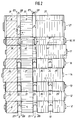
- Fig. 2 shows the inking rollers 18, 19 and the inking cylinder 17 in a second axial end position on the right side.
- the ink application rollers 18, 19 which move with the ink rubbing cylinder 17 in the axial direction G make it possible to apply different printing inks to two printing plates 31, 32 of maximum printing width each having a quarter cylinder width, and to a panorama printing plate 33 of maximum width which is half a cylinder wide.
- the maximum printing width is to be understood to mean that the distances between the color-free zones d are less than the distances between the color-free zones a at the ink fountain roller 2, so that there is no mixing of the printing inks by the second inking roller 17.
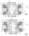
- FIG Representations in FIg. 4 and 5 a storage of the inking roller 18 is shown.
- Mechanically retractable pins 46, 47 are arranged in swivel-mounted bearing arms 43, 44, which engage non-positively in bearing bushes 48, 49, which are arranged on the two end faces of the inking roller 18.
- an inner ring 51, 52 of a deep groove ball bearing, generally designated 53, 54 is arranged in a force-locking manner.
- An outer ring 56, 57 of the deep groove ball bearing 53, 54 fits snugly against the inner circumference of a hollow cylindrical support body 58, 59, which protrudes from the end of a tubular roller body 61 of the inking roller 18.
- the roller body 61 has a jacket made of plastic covering 62, which forms the jacket surfaces 39, 41, 42 of the inking roller 18, which are each separated by annular grooves 37, 38.
- the annular grooves 37, 38 have such a depth, for. B. one to three mm, which ensures that only the outer surfaces 39, 41, 42 of the inking roller 18, 19 are wetted with printing ink.
- An inner ring 51, 52 of the deep groove ball bearing 53, 54 is ground by an amount h in the axial direction, so that the balls 66 have a tread surface 67, 68 widened by an amount h.
- the amount h also corresponds to the axial stroke length h of the inking roller 18.
- the outer ring 56, 57 has a known ball seat 69, 71. It is also possible to use the known ball seat 69, 71 in the inner ring 51, 52 and the ground tread, widened to the amount h 67, 68 to be arranged in the outer ring 56, 57.
- the deep groove ball bearings 53, 54 are held on both sides by retaining rings 72, 73.
- FIG. 5 shows the inking roller 18 in a second axial right end position according to FIG. 2.
- the inking roller 19 is mounted analogously to the inking roller 18.
- FIG. 6 shows a second exemplary embodiment of a mounting of an inking roller 18 or 19.
- Mechanically retractable pins 46, 47 which engage in bearing bushes 74, 76, are likewise arranged in pivotable bearing arms 43, 44 which are fixed on the side frame.
- an annular slide bearing 79, 81 is arranged, which is held in each case by a retaining ring 73.
- the inking roller 18 is in Fig. 6 in the right axial end position, so that the next stroke is to be carried out with a stroke length h to the left.
- the bearing bushes 74, 76 each have a cylindrical stop 82, 83 in the axial direction on their outside, which strikes against a limiting disk 84, 86 of the support body 77, 78 during the axial stroke movement of the inking roller 18.
- Limiting disks 84, 86 of this type are also provided in the bearing arrangements according to FIGS. 4 and 5.
- FIG. 7 shows a path-time diagram of the axial movement of the inking roller 18, 19 according to the invention in connection with the inking cylinder 17.
- a curve 91 shown in broken lines represents the movement sequence of one of the inking rollers 18, 19 and a further curve 92 represents the movement sequence of the inking cylinder 17.
- the inking roller 18 has reached its right axial end position according to curve 91 after passing through its axial stroke length h, ie from -h / 2 to + h / 2.
- the color friction cylinder 17 continues through its stroke distance + a / 2 to Time t2 continues according to curve 92 and assumes the position shown in FIGS. 2 and 5.
- the inking roller 18 gives up its persistence in the right axial end position according to FIG. 2 and is moved by friction with the ink rubbing cylinder 17 in the direction -h / 2 and at time t3 after completing the stroke length h after its left axial end position Fig. 1 reached.
- the inking cylinder 17 continues to move until the stroke distance a at the time t10 according to the representation according to curve 92. Thus, a total of one stroke of the four strokes shown in the diagram in FIG. 7 is completed.
- the other strokes t10 / t20, t20 / t30; t30 / t40 run in an analogous manner.
- the inking roller 18, 19 can of course be exchanged for a normal inking roller without recesses or ring grooves, unless it is necessary to produce two quarter-cylinder-wide prints of maximum width in addition to a half-cylinder-wide panorama print.
Landscapes
- Inking, Control Or Cleaning Of Printing Machines (AREA)
Applications Claiming Priority (2)
| Application Number | Priority Date | Filing Date | Title |
|---|---|---|---|
| DE4300683 | 1993-01-13 | ||
| DE4300683A DE4300683C2 (de) | 1993-01-13 | 1993-01-13 | Farbwerk für eine Rotationsdruckmaschine |
Publications (2)
| Publication Number | Publication Date |
|---|---|
| EP0606861A1 true EP0606861A1 (fr) | 1994-07-20 |
| EP0606861B1 EP0606861B1 (fr) | 1998-05-20 |
Family
ID=6478099
Family Applications (1)
| Application Number | Title | Priority Date | Filing Date |
|---|---|---|---|
| EP94100210A Expired - Lifetime EP0606861B1 (fr) | 1993-01-13 | 1994-01-08 | Dispositif d'encrage pour une machine à imprimer rotative |
Country Status (4)
| Country | Link |
|---|---|
| US (1) | US5406886A (fr) |
| EP (1) | EP0606861B1 (fr) |
| JP (1) | JP2752577B2 (fr) |
| DE (2) | DE4300683C2 (fr) |
Families Citing this family (14)
| Publication number | Priority date | Publication date | Assignee | Title |
|---|---|---|---|---|
| DE19628647B4 (de) * | 1996-07-16 | 2004-03-11 | Man Roland Druckmaschinen Ag | Farbtransportwalze für das Farbwerk einer Rollenrotationsdruckmaschine und Verfahren zur Herstellung der Walze |
| DE19628649C2 (de) * | 1996-07-16 | 1998-07-16 | Roland Man Druckmasch | Zwischen Panoramadruck und Druck von vier Farben nebeneinander umstellbares Farbwerk |
| DE19628648C1 (de) * | 1996-07-16 | 1998-02-12 | Roland Man Druckmasch | Zwischen Panoramadruck und Druck von vier Farben nebeneinander umstellbares Farbwerk |
| DE19750960C2 (de) * | 1996-11-26 | 2002-08-14 | Roland Man Druckmasch | Filmfarbwerk für eine Rotationsdruckmaschine |
| DE29812966U1 (de) | 1998-07-21 | 1998-09-24 | MAN Roland Druckmaschinen AG, 63075 Offenbach | Farbwerk für eine Offsetdruckmaschine |
| DE10118132B4 (de) | 2001-04-11 | 2005-04-14 | Koenig & Bauer Ag | Farbwerk einer Rotationsdruckmaschine |
| DE10329426B4 (de) * | 2003-07-01 | 2007-03-22 | Koenig & Bauer Ag | Farbwerk |
| DE102005030127A1 (de) | 2005-06-28 | 2007-01-04 | Maschinenfabrik Wifag | Gegenläufige Farbreiber |
| RU2309045C1 (ru) * | 2006-03-10 | 2007-10-27 | Владимир Николаевич Токарев | Печатная машина |
| JP2007309508A (ja) * | 2006-04-20 | 2007-11-29 | Kinyosha Co Ltd | 揺動ローラー、転がり軸受、ローラーの揺動方法 |
| DE102017202381A1 (de) | 2017-02-15 | 2018-08-16 | Kba-Metalprint Gmbh | Verfahren zum Bedrucken von Hohlkörpern |
| DE102017202382A1 (de) | 2017-02-15 | 2018-08-16 | Kba-Metalprint Gmbh | Verfahren zum Betrieb einer Vorrichtung zum Bedrucken von Hohlkörpern |
| DE102017202384A1 (de) | 2017-02-15 | 2018-08-16 | Kba-Metalprint Gmbh | Verfahren zum Bedrucken von Hohlkörpern |
| DE102017206392A1 (de) | 2017-04-13 | 2018-10-18 | Koenig & Bauer Ag | Segmentrad einer Vorrichtung zum Bedrucken von Hohlkörpern |
Citations (5)
| Publication number | Priority date | Publication date | Assignee | Title |
|---|---|---|---|---|
| US1675448A (en) * | 1927-06-06 | 1928-07-03 | Diamond Match Co | Inking mechanism for printing presses |
| US1915837A (en) * | 1931-06-08 | 1933-06-27 | George M Porter | Printing press |
| GB656076A (en) * | 1948-02-06 | 1951-08-08 | Goss Printing Press Co Ltd | Improvements in or relating to printing presses |
| EP0141058A2 (fr) * | 1983-10-25 | 1985-05-15 | Harris Graphics Corporation | Dispositif d'encrage pour une presse d'impression |
| JPS6235845A (ja) * | 1985-08-10 | 1987-02-16 | Shinriyou Seikan Kk | 印刷機のインキ装置 |
Family Cites Families (5)
| Publication number | Priority date | Publication date | Assignee | Title |
|---|---|---|---|---|
| US516620A (en) * | 1894-03-13 | Ink-distributer | ||
| SE383291B (sv) * | 1974-06-05 | 1976-03-08 | Svenska Elopak Ab | Anordning vid flexografiskt fergverk for tryckpress |
| DE3143909C2 (de) * | 1981-11-05 | 1983-11-03 | M.A.N.- Roland Druckmaschinen AG, 6050 Offenbach | Farbwerk für eine Offsetrotationsdruckmaschine |
| GB8605338D0 (en) * | 1986-03-04 | 1986-04-09 | Mccorquodale Commercial Produc | Colour printing |
| DE4007775C1 (fr) * | 1990-03-12 | 1991-09-19 | Skf Gmbh, 8720 Schweinfurt, De |
-
1993
- 1993-01-13 DE DE4300683A patent/DE4300683C2/de not_active Expired - Fee Related
-
1994
- 1994-01-08 EP EP94100210A patent/EP0606861B1/fr not_active Expired - Lifetime
- 1994-01-08 DE DE59405968T patent/DE59405968D1/de not_active Expired - Fee Related
- 1994-01-13 US US08/181,113 patent/US5406886A/en not_active Expired - Fee Related
- 1994-01-13 JP JP6002148A patent/JP2752577B2/ja not_active Expired - Fee Related
Patent Citations (5)
| Publication number | Priority date | Publication date | Assignee | Title |
|---|---|---|---|---|
| US1675448A (en) * | 1927-06-06 | 1928-07-03 | Diamond Match Co | Inking mechanism for printing presses |
| US1915837A (en) * | 1931-06-08 | 1933-06-27 | George M Porter | Printing press |
| GB656076A (en) * | 1948-02-06 | 1951-08-08 | Goss Printing Press Co Ltd | Improvements in or relating to printing presses |
| EP0141058A2 (fr) * | 1983-10-25 | 1985-05-15 | Harris Graphics Corporation | Dispositif d'encrage pour une presse d'impression |
| JPS6235845A (ja) * | 1985-08-10 | 1987-02-16 | Shinriyou Seikan Kk | 印刷機のインキ装置 |
Non-Patent Citations (1)
| Title |
|---|
| PATENT ABSTRACTS OF JAPAN vol. 11, no. 218 (M - 607) 15 July 1987 (1987-07-15) * |
Also Published As
| Publication number | Publication date |
|---|---|
| JP2752577B2 (ja) | 1998-05-18 |
| US5406886A (en) | 1995-04-18 |
| DE4300683A1 (de) | 1994-07-14 |
| DE59405968D1 (de) | 1998-06-25 |
| DE4300683C2 (de) | 1998-08-13 |
| JPH06238874A (ja) | 1994-08-30 |
| EP0606861B1 (fr) | 1998-05-20 |
Similar Documents
| Publication | Publication Date | Title |
|---|---|---|
| DE69818926T2 (de) | Druckmaschine mit selbstangetriebenen, fliegend gelagerten Zylindern | |
| EP0047861B1 (fr) | Dispositif d'encrage comprenant un cylindre d'encrage d'un mouvement de va-et-vient | |
| DE4300683C2 (de) | Farbwerk für eine Rotationsdruckmaschine | |
| EP1161345B1 (fr) | Groupe d'impression d'une presse d'imprimerie rotative | |
| EP0858887A1 (fr) | Machine à imprimer | |
| WO2005096691B1 (fr) | Unites d'impression d'une rotative a bobines | |
| EP1387767B1 (fr) | Systeme d'encrage a rouleaux | |
| DE69501218T2 (de) | Rotationsmaschine | |
| EP0980315A1 (fr) | Dispositif d'encrage | |
| DE3424721A1 (de) | Farbwerk fuer eine druckmaschine | |
| DE2309850C3 (de) | Rotationsdruckmaschine mit mehreren in Reihe angeordneten Druckwerken mit Bremseinrichtung | |
| DE2723103A1 (de) | Numerierdruckwerk | |
| EP0267504B1 (fr) | Palier pour rouleaux applicateurs à mouvement de va-et-vient dans les machines d'impression | |
| DE3400831C2 (de) | Farbkasten für eine Druckmaschine | |
| EP0189827B1 (fr) | Dispositif d'entraînement alternatif des rouleaux distributeurs d'au moins un système d'encrage d'une unité d'impression d'une rotative offset | |
| DE19746108C2 (de) | Antriebsanordnung für Druckzylinder einer Rotationsdruckmaschine | |
| DE9320273U1 (de) | Farbwerk für eine Rotationsdruckmaschine | |
| DE10202785B4 (de) | Druckmaschine mit einem Farb- und Feuchtwerk | |
| DE4300747C2 (de) | Rotationsdruckmaschine | |
| DE3211454C2 (de) | Rollenrotationsdruckmaschine für Endlosdruck | |
| EP1264691A1 (fr) | Groupe d'impression | |
| DE8630456U1 (de) | Lagerung für changierende Auftragwalzen von Druckmaschinen | |
| DE1812047A1 (de) | Farbwerk fuer Trockenoffsetmaschinen | |
| DE102010001594A1 (de) | Farbwerke und Druckeinheit einer Druckmaschine | |
| DE178182C (fr) |
Legal Events
| Date | Code | Title | Description |
|---|---|---|---|
| PUAI | Public reference made under article 153(3) epc to a published international application that has entered the european phase |
Free format text: ORIGINAL CODE: 0009012 |
|
| AK | Designated contracting states |
Kind code of ref document: A1 Designated state(s): CH DE FR GB IT LI SE |
|
| 17P | Request for examination filed |
Effective date: 19941219 |
|
| 17Q | First examination report despatched |
Effective date: 19950224 |
|
| RAP1 | Party data changed (applicant data changed or rights of an application transferred) |
Owner name: KOENIG & BAUER-ALBERT AKTIENGESELLSCHAFT |
|
| GRAG | Despatch of communication of intention to grant |
Free format text: ORIGINAL CODE: EPIDOS AGRA |
|
| GRAH | Despatch of communication of intention to grant a patent |
Free format text: ORIGINAL CODE: EPIDOS IGRA |
|
| ITF | It: translation for a ep patent filed | ||
| GRAH | Despatch of communication of intention to grant a patent |
Free format text: ORIGINAL CODE: EPIDOS IGRA |
|
| GRAA | (expected) grant |
Free format text: ORIGINAL CODE: 0009210 |
|
| AK | Designated contracting states |
Kind code of ref document: B1 Designated state(s): CH DE FR GB IT LI SE |
|
| REG | Reference to a national code |
Ref country code: CH Ref legal event code: EP |
|
| ET | Fr: translation filed | ||
| GBT | Gb: translation of ep patent filed (gb section 77(6)(a)/1977) |
Effective date: 19980520 |
|
| REF | Corresponds to: |
Ref document number: 59405968 Country of ref document: DE Date of ref document: 19980625 |
|
| RAP2 | Party data changed (patent owner data changed or rights of a patent transferred) |
Owner name: KOENIG & BAUER AKTIENGESELLSCHAFT |
|
| PLBE | No opposition filed within time limit |
Free format text: ORIGINAL CODE: 0009261 |
|
| STAA | Information on the status of an ep patent application or granted ep patent |
Free format text: STATUS: NO OPPOSITION FILED WITHIN TIME LIMIT |
|
| 26N | No opposition filed | ||
| REG | Reference to a national code |
Ref country code: GB Ref legal event code: IF02 |
|
| PGFP | Annual fee paid to national office [announced via postgrant information from national office to epo] |
Ref country code: SE Payment date: 20050120 Year of fee payment: 12 |
|
| PG25 | Lapsed in a contracting state [announced via postgrant information from national office to epo] |
Ref country code: SE Free format text: LAPSE BECAUSE OF NON-PAYMENT OF DUE FEES Effective date: 20060109 |
|
| PGFP | Annual fee paid to national office [announced via postgrant information from national office to epo] |
Ref country code: IT Payment date: 20060131 Year of fee payment: 13 |
|
| EUG | Se: european patent has lapsed | ||
| PGFP | Annual fee paid to national office [announced via postgrant information from national office to epo] |
Ref country code: CH Payment date: 20080115 Year of fee payment: 15 |
|
| PGFP | Annual fee paid to national office [announced via postgrant information from national office to epo] |
Ref country code: GB Payment date: 20080109 Year of fee payment: 15 Ref country code: DE Payment date: 20080311 Year of fee payment: 15 |
|
| PGFP | Annual fee paid to national office [announced via postgrant information from national office to epo] |
Ref country code: FR Payment date: 20080111 Year of fee payment: 15 |
|
| REG | Reference to a national code |
Ref country code: CH Ref legal event code: PL |
|
| GBPC | Gb: european patent ceased through non-payment of renewal fee |
Effective date: 20090108 |
|
| PG25 | Lapsed in a contracting state [announced via postgrant information from national office to epo] |
Ref country code: IT Free format text: LAPSE BECAUSE OF NON-PAYMENT OF DUE FEES Effective date: 20070108 |
|
| PG25 | Lapsed in a contracting state [announced via postgrant information from national office to epo] |
Ref country code: LI Free format text: LAPSE BECAUSE OF NON-PAYMENT OF DUE FEES Effective date: 20090131 Ref country code: DE Free format text: LAPSE BECAUSE OF NON-PAYMENT OF DUE FEES Effective date: 20090801 Ref country code: CH Free format text: LAPSE BECAUSE OF NON-PAYMENT OF DUE FEES Effective date: 20090131 |
|
| REG | Reference to a national code |
Ref country code: FR Ref legal event code: ST Effective date: 20091030 |
|
| PG25 | Lapsed in a contracting state [announced via postgrant information from national office to epo] |
Ref country code: GB Free format text: LAPSE BECAUSE OF NON-PAYMENT OF DUE FEES Effective date: 20090108 |
|
| PG25 | Lapsed in a contracting state [announced via postgrant information from national office to epo] |
Ref country code: FR Free format text: LAPSE BECAUSE OF NON-PAYMENT OF DUE FEES Effective date: 20090202 |