EP0606865B1 - Dispositif d'orientation pour store à lamelles - Google Patents
Dispositif d'orientation pour store à lamelles Download PDFInfo
- Publication number
- EP0606865B1 EP0606865B1 EP94100226A EP94100226A EP0606865B1 EP 0606865 B1 EP0606865 B1 EP 0606865B1 EP 94100226 A EP94100226 A EP 94100226A EP 94100226 A EP94100226 A EP 94100226A EP 0606865 B1 EP0606865 B1 EP 0606865B1
- Authority
- EP
- European Patent Office
- Prior art keywords
- cord
- housing
- lamellae
- blades
- affixed
- Prior art date
- Legal status (The legal status is an assumption and is not a legal conclusion. Google has not performed a legal analysis and makes no representation as to the accuracy of the status listed.)
- Expired - Lifetime
Links
- 238000004804 winding Methods 0.000 claims description 5
- 206010045453 Umbilical cord short Diseases 0.000 abstract 5
- 238000004873 anchoring Methods 0.000 description 1
Images
Classifications
-
- E—FIXED CONSTRUCTIONS
- E06—DOORS, WINDOWS, SHUTTERS, OR ROLLER BLINDS IN GENERAL; LADDERS
- E06B—FIXED OR MOVABLE CLOSURES FOR OPENINGS IN BUILDINGS, VEHICLES, FENCES OR LIKE ENCLOSURES IN GENERAL, e.g. DOORS, WINDOWS, BLINDS, GATES
- E06B9/00—Screening or protective devices for wall or similar openings, with or without operating or securing mechanisms; Closures of similar construction
- E06B9/24—Screens or other constructions affording protection against light, especially against sunshine; Similar screens for privacy or appearance; Slat blinds
- E06B9/26—Lamellar or like blinds, e.g. venetian blinds
- E06B9/28—Lamellar or like blinds, e.g. venetian blinds with horizontal lamellae, e.g. non-liftable
- E06B9/30—Lamellar or like blinds, e.g. venetian blinds with horizontal lamellae, e.g. non-liftable liftable
- E06B9/303—Lamellar or like blinds, e.g. venetian blinds with horizontal lamellae, e.g. non-liftable liftable with ladder-tape
- E06B9/307—Details of tilting bars and their operation
Definitions
- the present invention relates to a device for orienting the slats of a so-called Venetian blind.
- orientation devices are also known, also known as variators, for example patents CH 400 817 and 454 417 or patent EP 0 190 626, which comprise a winding coil mounted in a housing on a control shaft. horizontal and subjected to the action of elastic braking means.
- the two cords to which the blind slats are attached are fixed by one of their ends to said coil and are therefore rotated therewith.
- This feature has the disadvantage that the weight of the slats is exerted on the two cords and varies according to the position of the blind, so that the handling of the dimmer is more or less difficult to perform depending on this position.
- the known devices in principle require the presence of a relatively complex system to maintain the slats in their approximately vertical position, therefore closed.
- the object of this invention therefore consists in providing a device for orienting the slats of a blind of the aforementioned type, but which does not have the aforementioned drawbacks of the known devices.
- the device for orienting the slats of a blind which is the subject of the present invention and which aims to achieve the above object, is distinguished by the characteristics defined. in claim 1.
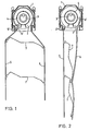
- Figures 1 and 2 are side views partially in vertical section and showing the device in its positions corresponding to the respectively open and closed positions of the slats.
- the embodiment of the device according to the invention comprises a housing 1 in which a winding coil 2 is rotatably mounted on a transverse control axis 3.
- the rotation of this coil 2 is subject in a manner known in itself to the action of a braking spring 4 wound around said control axis 3.
- the illustrated device also includes a first cord 5 fixed by its upper end to the housing 1, and a second cord 6 secured by its upper end to the winding coil 2, the respective anchoring points being designated by the reference numerals 5 'and 6'. Between the two cords 5,6 are mounted the slats 7 of the blind, which are more particularly articulated on pivot points 8,9.
- the device also comprises a traction strip not illustrated here and acting in a manner known per se to control the raising, respectively the lowering, of the blind slats.
- the slats 7 are therefore practically horizontal (angle of approximately 90 ° with the vertical), while in the position "closed” illustrated in FIG. 2, they are practically vertical (angle of about 0 °).
- the strips 7 can be oriented at any angle between approximately 0 ° and 90 °, the point of articulation 8 of the strips 7 on the fixed cord 5 remaining in the same position , while the other point of articulation 9 on the cord 6 secured to the winding coil describes an arc between the two extreme positions described above.
- Another advantage of the device according to the invention consists in the fact that, when the maneuver for lowering the blind is completed, all the slats 7 remain automatically positioned practically vertically, as illustrated in FIG. 2, that is to say in contact with each other under the effect of their own weight, without it being necessary to tighten later the cord which supports them, unlike the known devices which must be provided with a relatively sophisticated and thereby expensive system intended to provide the strips with the tension necessary to remain in said position.
- the design of the device for orienting the slats of a blind according to the invention offers the possibility of providing two different centers between the traction strip (not shown) and the cords, one of the two being fixed to the housing, which allows manufacturers to use the same variator, regardless of whether they have their machine adjusted for a center distance of 11 mm or 24 mm, for example.
- the device according to the invention can be combined with a conventional system in which the two cords are integral with the control coil.
Landscapes
- Engineering & Computer Science (AREA)
- Structural Engineering (AREA)
- Architecture (AREA)
- Civil Engineering (AREA)
- Blinds (AREA)
- Specific Sealing Or Ventilating Devices For Doors And Windows (AREA)
- Operating, Guiding And Securing Of Roll- Type Closing Members (AREA)
Description
- La présente invention concerne un dispositif d'orientation des lamelles d'un store dit vénitien.
- On connaît déjà de nombreuses réalisations de tels dispositifs d'orientation dénommés également variateurs, par exemple des brevets CH 400 817 et 454 417 ou du brevet EP 0 190 626, qui comportent une bobine d'enroulement montée dans un boîtier sur un axe de commande horizontal et soumise à l'action de moyens élastiques de freinage. Dans tous les dispositifs connus, les deux cordelettes auxquelles sont attachées les lamelles du store sont fixées par une de leurs extrémités à ladite bobine et sont par conséquent entraînées en rotation avec celle-ci. Cette particularité présente le désavantage que le poids des lamelles s'exerce sur les deux cordelettes et varie en fonction de la position du store, de telle sorte que la manipulation du variateur est plus ou moins difficile à effectuer selon cette position. De plus, les dispositifs connus nécessitent en principe la présence d'un système relativement complexe pour maintenir les lamelles dans leur position approximativement verticale donc fermée.
- Le but de cette invention consiste donc à fournir un dispositif d'orientation des lamelles d'un store du type précité, mais qui ne présente pas les inconvénients précités des dispositifs connus.
- Le dispositif d'orientation des lamelles d'un store, objet de la présente invention et visant à atteindre le but ci-dessus, se distingue par les caratéristiques définies dans la revendication 1.
- Le dessin annexé illustre de manière schématique et à titre d'exemple une forme d'exécution du dispositif selon l'invention.
- Les figures 1 et 2 en sont des vues latérales partiellement en coupe verticale et montrant le dispositif dans ses positions correspondant aux positions respectivement ouverte et fermée des lamelles.
- En référence aux figures 1 et 2, la forme d'exécution du dispositif selon l'invention comporte un boîtier 1 dans lequel est montée rotative une bobine d'enroulement 2 sur un axe transversal de commande 3. La rotation de cette bobine 2 est soumise de manière connue en elle-même à l'action d'un ressort de freinage 4 enroulé autour dudit axe de commande 3.
- Le dispositif illustré comporte encore une première cordelette 5 fixée par son extrémité supérieure au boîtier 1, et une seconde cordelette 6 solidaire par son extrémité supérieure de la bobine d'enroulement 2, les points d'ancrage respectifs étant désignés par les chiffres de référence 5' et 6'. Entre les deux cordelettes 5,6 sont montées les lamelles 7 du store, lesquelles sont plus particulièrement articulées sur des points de pivotement 8,9.
- Bien entendu, le dispositif comporte également une bande de traction non illustrée ici et agissant de manière connue en elle-même pour commander la montée, respectivement la descente, des lamelles du store.
- Dans la position "ouverte" illustrée sur la figure 1, les lamelles 7 sont donc pratiquement horizontales (angle d'environ 90° avec la verticale), alors que dans la position "fermée" illustrée sur la figure 2, elles sont pratiquement verticales (angle d'environ 0°).
- On constate ainsi que, grâce à la présente invention, dans la position verticale précitée (figure 2), le poids des lamelles 7 est supporté lors de la manoeuvre de descente du store par la seule cordelette fixe 5, lesdites lamelles 7 restant suspendues par leur point d'articulation 8 à celle-ci. Quelle que soit la position du store, la force exercée par le poids des lamelles 7 sur le ressort de freinage 4 reste donc nulle, et la manipulation du store, plus particulièrement pour sa descente, demande toujours le même effort. Le fait que tout le poids des lamelles 7 est supporté par la cordelette fixe 5 permet donc au dispositif de freinage ressort 4 enroulé autour de l'axe de la bobine 2 de travailler "librement", c'est-à-dire indépendamment de la manoeuvre de descente ou de montée des lamelles 7. Bien entendu, les lamelles 7 peuvent être orientées selon un angle quelconque entre environ 0° et 90°, le point d'articulation 8 des lamelles 7 sur la cordelette fixe 5 restant dans la même position, alors que l'autre point d'articulation 9 sur la cordelette 6 solidaire de la bobine d'enroulement décrit un arc de cercle entre les deux positions extrêmes décrites précédemment.
- Un autre avantage du dispositif selon l'invention consiste dans le fait que, lorsque la manoeuvre de descente du store est terminée, toutes les lamelles 7 restent automatiquement positionnées pratiquement verticalement, comme illustré sur la figure 2, c'est-à-dire en contact les unes avec les autres sous l'effet de leur propre poids, sans qu'il soit nécessaire de tendre ultérieurement la cordelette qui les soutient, contrairement aux dispositifs connus qui doivent être pourvus d'un système relativement sophistiqué et par là coûteux destiné à fournir aux lamelles la tension nécessaire pour rester dans ladite position.
- Enfin, on peut encore relever que la conception du dispositif d'orientation des lamelles d'un store selon l'invention offre la possibilité de prévoir deux entre-axes différents entre la bande de traction (non illustrée) et les cordelettes, l'une des deux étant fixée au boîtier, ce qui permet aux constructeurs d'utiliser le même variateur, indépendamment du fait qu'ils aient leur machine réglée pour un entre-axe de 11 mm ou de 24 mm, par exemple. De plus, selon une variante non illustrée, le dispositif selon l'invention peut être combiné avec un système conventionnel dans lequel les deux cordelettes sont solidaires de la bobine de commande.
Claims (3)
- Dispositif d'orientation des lamelles d'un store comportant une bobine d'enroulement montée dans un boîtier sur un axe de commande horizontal et soumise à l'action de moyens élastiques de freinage, caractérisé par le fait qu'une première cordelette est fixée par son extrémité supérieure au boîtier et une seconde cordelette est solidaire, par son extrémité supérieure, de ladite bobine, et par le fait que les lamelles sont articulées entre les deux cordelettes de telle sorte qu'elles puissent être orientées entre une position ouverte dans laquelle les lamelles sont pratiquement horizontales et une position fermée dans laquelle ces lamelles sont pratiquement verticales, le point d'articulation des lamelles sur la cordelette fixée au boîtier restant stationnaire et celui sur la cordelette solidaire de la bobine décrivant un arc de cercle durant le passage d'une position précitée à l'autre.
- Dispositif d'orientation selon la revendication 1, caractérisé par le fait que les moyens élastiques de freinage sont constitués par un ressort enroulé autour de l'axe de commande et solidaire de ladite bobine.
- Dispositif selon la revendication 1 ou la revendication 2, caractérisé par le fait qu'il présente au moins deux entre-axes différents entre les deux cordelettes et la bande de traction du store.
Applications Claiming Priority (2)
| Application Number | Priority Date | Filing Date | Title |
|---|---|---|---|
| CH00122/93A CH687634A5 (fr) | 1993-01-15 | 1993-01-15 | Dispositif d'orientation pour store à lamelles. |
| CH122/93 | 1993-01-15 |
Publications (2)
| Publication Number | Publication Date |
|---|---|
| EP0606865A1 EP0606865A1 (fr) | 1994-07-20 |
| EP0606865B1 true EP0606865B1 (fr) | 1997-03-26 |
Family
ID=4179761
Family Applications (1)
| Application Number | Title | Priority Date | Filing Date |
|---|---|---|---|
| EP94100226A Expired - Lifetime EP0606865B1 (fr) | 1993-01-15 | 1994-01-08 | Dispositif d'orientation pour store à lamelles |
Country Status (4)
| Country | Link |
|---|---|
| EP (1) | EP0606865B1 (fr) |
| AT (1) | ATE150839T1 (fr) |
| CH (1) | CH687634A5 (fr) |
| DE (1) | DE69402215T2 (fr) |
Families Citing this family (1)
| Publication number | Priority date | Publication date | Assignee | Title |
|---|---|---|---|---|
| CH713681A2 (de) | 2017-04-10 | 2018-10-15 | Storenmaterial Ag | Vorrichtung und Verfahren zur Ausrichtung von Lamellen einer Jalousie und Jalousie mit einer Lamellen-Ausricht-Vorrichtung. |
Family Cites Families (4)
| Publication number | Priority date | Publication date | Assignee | Title |
|---|---|---|---|---|
| US2222226A (en) * | 1940-02-07 | 1940-11-19 | Harold R Haase | Tilt gear unit for venetian blinds |
| GB737060A (en) * | 1953-01-26 | 1955-09-21 | Atvidabergs Butiksinredningar | Improvements in or relating to venetian blinds |
| GB740211A (en) * | 1953-02-14 | 1955-11-09 | Oreste Berni | Improvements in venetian blinds |
| NL8602004A (nl) * | 1986-08-06 | 1987-10-01 | Hunter Douglas Ind Bv | Lamellenjaloezie met horizontale lamellen en met een gecombineerde bediening voor kantelen en optrekken. |
-
1993
- 1993-01-15 CH CH00122/93A patent/CH687634A5/fr not_active IP Right Cessation
-
1994
- 1994-01-08 DE DE69402215T patent/DE69402215T2/de not_active Expired - Lifetime
- 1994-01-08 EP EP94100226A patent/EP0606865B1/fr not_active Expired - Lifetime
- 1994-01-08 AT AT94100226T patent/ATE150839T1/de not_active IP Right Cessation
Also Published As
| Publication number | Publication date |
|---|---|
| DE69402215T2 (de) | 1998-01-02 |
| CH687634A5 (fr) | 1997-01-15 |
| EP0606865A1 (fr) | 1994-07-20 |
| DE69402215D1 (de) | 1997-04-30 |
| ATE150839T1 (de) | 1997-04-15 |
Similar Documents
| Publication | Publication Date | Title |
|---|---|---|
| CA1256830A (fr) | Appareil de distribution et de coupe simultanees de bandes de materiaux enroules, avec au moins un rouleau de materiau en service | |
| EP0394124A1 (fr) | Store à enrouleur motorisé | |
| EP0500499B1 (fr) | Store vénitien | |
| EP1488069B1 (fr) | Mecanisme de tension d'un ressort de compensation pour installation de fermeture ou de protection solaire | |
| EP1469766B1 (fr) | Dispositif de controle et de regulation de la pression d'une bobine de materiau dans un appareil distributeur a coupe automatique | |
| EP1486452A2 (fr) | Systeme de levage et de stabilisation d'un support de charge suspendu | |
| EP0765806A1 (fr) | Enrouleur-réducteur de voilure pour grand-voile | |
| WO2005026473A1 (fr) | Dispositif et procede pour recouvrir et decouvrir une surface par un element de couverture enroulable | |
| EP0524064A1 (fr) | Mobile radiologique | |
| EP0606865A1 (fr) | Dispositif d'orientation pour store à lamelles | |
| EP2360339B1 (fr) | Actionneur à bras pour vantail | |
| EP0795504A1 (fr) | Machine à dérouler des bobines en continu comportant au moins un moyen de déroulage de deux bobines jumelées ou coaxiales simultanément | |
| EP1380793B1 (fr) | Dispositif mécanique pour le déplacement d'un appareil de prises de vues | |
| EP0651849B1 (fr) | Dispositif d'actionnement d'un element obturateur pivotant | |
| FR2591650A1 (fr) | Dispositif de manoeuvre pour volets ou persiennes a un ou deux vantaux pivotants | |
| EP2076651A2 (fr) | Dispositif d'enroulement de cordon de suspension de store | |
| EP1096094A1 (fr) | Dispositif à vérin pour l'ouverture/fermeture d'un vantail | |
| FR2578893A1 (fr) | Porte basculante, notamment porte de garage | |
| FR2823238A1 (fr) | Store comprenant des moyens d'eclairage perfectionnes | |
| FR2487422A1 (fr) | Perfectionnements aux dispositifs de verrouillage automatique de volets roulants | |
| EP1077303A1 (fr) | Système de volet comportant un volet roulant | |
| FR2623559A2 (fr) | Dispositif d'inclinaison pour des stores venitiens | |
| CH691325A5 (fr) | Dispositif d'orientation différentiel pour store à lamelles. | |
| FR2803328A1 (fr) | Motorisation pour orienter les lames mobiles de volets roulants quelques soit leur position de fermeture | |
| FR2459775A2 (fr) | Dispositif de debrayage et de reglage instantane des fins de course d'un enrouleur automatique |
Legal Events
| Date | Code | Title | Description |
|---|---|---|---|
| PUAI | Public reference made under article 153(3) epc to a published international application that has entered the european phase |
Free format text: ORIGINAL CODE: 0009012 |
|
| AK | Designated contracting states |
Kind code of ref document: A1 Designated state(s): AT BE DE FR IT NL SE |
|
| 17P | Request for examination filed |
Effective date: 19940906 |
|
| GRAG | Despatch of communication of intention to grant |
Free format text: ORIGINAL CODE: EPIDOS AGRA |
|
| 17Q | First examination report despatched |
Effective date: 19960510 |
|
| GRAH | Despatch of communication of intention to grant a patent |
Free format text: ORIGINAL CODE: EPIDOS IGRA |
|
| GRAH | Despatch of communication of intention to grant a patent |
Free format text: ORIGINAL CODE: EPIDOS IGRA |
|
| GRAA | (expected) grant |
Free format text: ORIGINAL CODE: 0009210 |
|
| AK | Designated contracting states |
Kind code of ref document: B1 Designated state(s): AT BE DE FR IT NL SE |
|
| PG25 | Lapsed in a contracting state [announced via postgrant information from national office to epo] |
Ref country code: NL Free format text: LAPSE BECAUSE OF FAILURE TO SUBMIT A TRANSLATION OF THE DESCRIPTION OR TO PAY THE FEE WITHIN THE PRESCRIBED TIME-LIMIT Effective date: 19970326 Ref country code: IT Free format text: LAPSE BECAUSE OF FAILURE TO SUBMIT A TRANSLATION OF THE DESCRIPTION OR TO PAY THE FEE WITHIN THE PRE;WARNING: LAPSES OF ITALIAN PATENTS WITH EFFECTIVE DATE BEFORE 2007 MAY HAVE OCCURRED AT ANY TIME BEFORE 2007. THE CORRECT EFFECTIVE DATE MAY BE DIFFERENT FROM THE ONE RECORDED.SCRIBED TIME-LIMIT Effective date: 19970326 Ref country code: FR Free format text: THE PATENT HAS BEEN ANNULLED BY A DECISION OF A NATIONAL AUTHORITY Effective date: 19970326 Ref country code: AT Effective date: 19970326 |
|
| REF | Corresponds to: |
Ref document number: 150839 Country of ref document: AT Date of ref document: 19970415 Kind code of ref document: T |
|
| REF | Corresponds to: |
Ref document number: 69402215 Country of ref document: DE Date of ref document: 19970430 |
|
| PG25 | Lapsed in a contracting state [announced via postgrant information from national office to epo] |
Ref country code: SE Effective date: 19970626 |
|
| NLV1 | Nl: lapsed or annulled due to failure to fulfill the requirements of art. 29p and 29m of the patents act | ||
| PLBE | No opposition filed within time limit |
Free format text: ORIGINAL CODE: 0009261 |
|
| STAA | Information on the status of an ep patent application or granted ep patent |
Free format text: STATUS: NO OPPOSITION FILED WITHIN TIME LIMIT |
|
| PG25 | Lapsed in a contracting state [announced via postgrant information from national office to epo] |
Ref country code: BE Free format text: LAPSE BECAUSE OF NON-PAYMENT OF DUE FEES Effective date: 19980131 |
|
| 26N | No opposition filed | ||
| BERE | Be: lapsed |
Owner name: CHERUBINI ITALO Effective date: 19980131 |
|
| REG | Reference to a national code |
Ref country code: FR Ref legal event code: ST |
|
| PGFP | Annual fee paid to national office [announced via postgrant information from national office to epo] |
Ref country code: DE Payment date: 20130122 Year of fee payment: 20 |
|
| REG | Reference to a national code |
Ref country code: DE Ref legal event code: R071 Ref document number: 69402215 Country of ref document: DE |
|
| REG | Reference to a national code |
Ref country code: DE Ref legal event code: R071 Ref document number: 69402215 Country of ref document: DE |
|
| PG25 | Lapsed in a contracting state [announced via postgrant information from national office to epo] |
Ref country code: DE Free format text: LAPSE BECAUSE OF EXPIRATION OF PROTECTION Effective date: 20140109 |