EP0606878A1 - Plaque de porte pour une serrure à cylindre - Google Patents
Plaque de porte pour une serrure à cylindre Download PDFInfo
- Publication number
- EP0606878A1 EP0606878A1 EP94100269A EP94100269A EP0606878A1 EP 0606878 A1 EP0606878 A1 EP 0606878A1 EP 94100269 A EP94100269 A EP 94100269A EP 94100269 A EP94100269 A EP 94100269A EP 0606878 A1 EP0606878 A1 EP 0606878A1
- Authority
- EP
- European Patent Office
- Prior art keywords
- cover cap
- rosette
- opening
- bottom part
- intended
- Prior art date
- Legal status (The legal status is an assumption and is not a legal conclusion. Google has not performed a legal analysis and makes no representation as to the accuracy of the status listed.)
- Granted
Links
- 230000002093 peripheral effect Effects 0.000 claims description 3
- 238000003801 milling Methods 0.000 claims 1
- 210000002105 tongue Anatomy 0.000 description 19
- 210000001331 nose Anatomy 0.000 description 6
- 239000004677 Nylon Substances 0.000 description 3
- 229910000831 Steel Inorganic materials 0.000 description 3
- 229920001778 nylon Polymers 0.000 description 3
- 239000010959 steel Substances 0.000 description 3
- 239000000853 adhesive Substances 0.000 description 2
- 238000004026 adhesive bonding Methods 0.000 description 2
- 230000001070 adhesive effect Effects 0.000 description 2
- 238000004873 anchoring Methods 0.000 description 1
- 238000013475 authorization Methods 0.000 description 1
- 238000006073 displacement reaction Methods 0.000 description 1
- 230000000694 effects Effects 0.000 description 1
- 238000002347 injection Methods 0.000 description 1
- 239000007924 injection Substances 0.000 description 1
- 239000000463 material Substances 0.000 description 1
- 239000002184 metal Substances 0.000 description 1
- 239000002991 molded plastic Substances 0.000 description 1
- 239000004033 plastic Substances 0.000 description 1
- 230000007704 transition Effects 0.000 description 1
Images

Classifications
-
- E—FIXED CONSTRUCTIONS
- E05—LOCKS; KEYS; WINDOW OR DOOR FITTINGS; SAFES
- E05B—LOCKS; ACCESSORIES THEREFOR; HANDCUFFS
- E05B15/00—Other details of locks; Parts for engagement by bolts of fastening devices
- E05B15/02—Striking-plates; Keepers; Bolt staples; Escutcheons
Definitions
- the invention relates to a rosette of the type specified in the preamble of claim 1.
- a burglar protection rosette of the type mentioned in which the lower part is preferably made of steel, is held by screws screwed in from the inside of the door or at least covered and has such a thickness that the locking cylinder in the assembled state only so much protrudes beyond the lower part that its end is essentially flush with its surface after the cap has been put on. This ensures on the one hand that the locking cylinder has no starting points for a tool. On the other hand, it is also practically impossible to loosen the lower part because, due to its conical outer circumference, it does not have sufficiently large areas that could be gripped with pliers or the like in order to rotate or otherwise loosen the lower part.
- a disadvantage of this rosette is that a conical lower part does not offer the possibility of putting on and attaching a top cap, if one of these known fasteners such as undercuts for snap connections, threaded parts for screw closures or the like.
- the attachment of such fasteners on the peripheral edges of the lower parts would namely have the result that the desired smooth and conical surface must be at least partially interrupted. This would in turn offer the possibility of attaching a tool after a possibly violent removal of the cover cap, which should be avoided. Therefore, it has hitherto been necessary either to provide no cover cap at all or to attach the cover cap to the lower part by gluing, which is undesirable simply because of the inseparable connection formed thereby.
- cover caps are also undesirable because at least the cover cap is often made of plastic, in particular nylon, and no sufficiently durable steel / nylon adhesive is available. Apart from this, the cover caps would have to be given a shape which is specially adapted to the conical outer circumference of the lower part, which is unsatisfied for formal reasons or is associated with high costs.
- the invention has for its object to form a rosette of the type mentioned in such a way that the cover cap can be attached to the lower part in a simple manner and without gluing, without this having to be provided with fastening means, which at least after a violent removal of the cover cap Allow loosening or loosening of the lower part.
- the invention has the advantage that the tongue attached to the cover cap is arranged in the assembled state of the rosette and the locking cylinder on the edge of the opening in both the lower part and the cover cap. This keeps her nose firmly engaged with the step of the base by the lock cylinder. Even with a violent removal of the cover cap, it should hardly be possible to manipulate the tongue part protruding into the opening. But even if this were possible, the narrow gap which is thereby freed between the lower part and the locking cylinder would not be a suitable means of attaching a conventional tool, so that there is a high degree of security against burglary. Finally is it is possible to use cover caps of the usual shape.
- a cover cap 1 of the rosette according to the invention contains an essentially plane-parallel, for example circular disc 2, which is provided in its central part with an opening 3 for a profile lock cylinder 4 indicated by a broken line in FIG. 3 and on the rear side a vertical one protruding, peripheral edge portion 5.
- at least one tongue 6 is formed on the back of the disc 2, which, like the rudder section 5, projects vertically backwards and at its free end with an undercut, essentially radially outwards directed nose 7 is provided.
- a plurality of such tongues 6 are preferably provided and arranged distributed around the circumference of the opening 3.
- FIG. 1 there are four tongues 6. As shown in FIG. 2 in particular, all the tongues 6 directly adjoin the inner contour of the opening 3, so that they extend in the rearward direction like a collar.
- the cap 1 is preferably made of an injection molded plastic, especially nylon part.
- a lower part 9 of the rosette according to the invention is only shown in section in FIG. 3. It essentially consists of a plane-parallel disk 10, which is preferably made of metal, in particular steel, and is conical on the outer circumference 11.
- the lower part 9 has an opening for the profile locking cylinder 4 (FIG. 3), which has the same size and inner contour as the opening 3 of the cover cap 1 and, in the assembled state, runs coaxially with it.
- a recess 12 reaching to the edge of the opening is provided in the lower part 9, where one of the tongues 6 comes to rest in the assembled state of the rosette. In the exemplary embodiment there are therefore four such cutouts 12. Alternatively, it would be possible to design at least one of the recesses 12 so that it can accommodate several of the tongues 6.
- each recess is so large in its upper region, which borders on the front or top of the lower part 9 facing the cover cap 1, that it can just accommodate the associated tongue 6 in the assembled state.
- each recess 12 in the rear area which borders the rear or underside of the lower part 9 facing the mounting surface, is provided with a radially outwardly directed step 14, which forms a transition to a widened part of the recess 12.
- This stage 14 is mounted at such a height that it is in the assembled state of the rosette shown in FIG. 3, backlash-free as far behind as possible at least from the nose 7 of a tongue 6 projecting into the recess 12 and therefore the cover cap 1 in the axial direction Lower part 9 defines.
- the arrangement is preferably such that, in the assembled state, the edge section 5 of the cover cap 1 and the one with the largest diameter
- the underside of the conical lower part 9 rests on the respective mounting surface, for example a door leaf
- the underside of the pane 2 rests on the upper side of the pane 10
- the edge section 5 borders closely on the underside of the outer circumference 11.
- the rosette is assembled by first attaching the lower part 9 to the mounting surface, e.g. fastening screws introduced from the rear of a door are screwed into threaded bores (not shown) bordering on the underside of the lower part 9. 3, the cover cap 1 is pressed onto the lower part 9, the tongues 7 engaging behind the steps 14. Finally, the profile locking cylinder 4 is introduced, the outer contour of which corresponds exactly to the inner contour of the opening 3. As a result, in the assembled state, the lateral surface of the profile locking cylinder 4 lies tightly against the wall sections of the tongues 6 bordering the opening 3, as a result of which they are prevented from evading laterally. The connections formed by the lugs 7 and steps 14 are therefore locked as long as the profile locking cylinder 4 is mounted. After dismantling the connection, however, can easily be released again, since the lugs 7 can now deflect or be bent away laterally onto the cover cap 1 when exercising a tilting movement.
- the loosening of the connection can be facilitated in that the tongues 6 are easily elastically bendable or are designed such that at least the lugs 7 protrude into the area of the opening in the unassembled state. Pulling the profile locking cylinder out of the opening 3 would therefore result in the connection being released automatically.
- the lugs 7 could be provided at their upper ends with demolding bevels which facilitate the release of the cover cap 1.
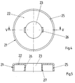
- a cover cap 21 is provided, which essentially corresponds to the cover cap 1 and a circular disc 22, an opening 23 for a cylindrical cylinder 24 here (FIG. 7), an edge section 25, tongues 26 and Noses 27 has. Except for the differences that, compared to FIGS. 1 and 2, the opening 23 has a circular cross section which corresponds exactly to the cross section of the locking cylinder 24 and only two instead of four tongues 26 are provided, the cap 21 differs from the cap 1 in that the height of the tongues 26 is substantially equal to the height of the edge portion 25.
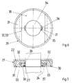
- a lower part 29 (FIG. 6) of the rosette is in two parts compared to FIGS. 1 and 2 and is composed of a fastening part 30 and a cover part 31.
- the fastening part 30 has bores (not shown) for fastening screws which are screwed in from the mounting side of the door or the like, and two straight, parallel, laterally projecting guide webs 32 which are at a certain distance from the underside which lies on the door are arranged.
- the cover part 31 is conical on its outer circumference analogous to the lower part 9 according to FIG. 3 and is provided on its underside with a recess corresponding to the shape of the fastening part 30 and with two guide grooves 33 aligned with the guide webs 32 and adapted to them.
- the cover part 31 can be pushed onto the fastening part 30 in a direction parallel to the door leaf or the like by means of the guide webs 32 and guide grooves 33, which preferably form a dovetail guide ( Fig. 7).
- the guides 32, 33 prevent the cover part 31 from being moved perpendicular to it or perpendicular to the door leaf or the like after being pushed onto the fastening part 30.
- the fastening part 30 and the cover part 31 each have an opening 34 which essentially corresponds to the outer contour of the locking cylinder 24 and the opening 23 of the cover cap 21.
- both the fastening part 30 and the cover part 31 are provided with cutouts 35 which adjoin the openings 34 and which essentially correspond to the cutouts 12 according to FIG. 3.
- the recess 35 of the fastening part 30 is provided in the immediate vicinity of its underside with a step 36 which is formed by an obliquely outward cross-sectional widening 37 of the recess 35.
- the rosette according to FIGS. 4 to 7 is assembled by first fastening the fastening part 30 to the door leaf or the like. Then the cover part 31 is pushed on, the cover cap 21 is pressed on and the locking cylinder 24 is inserted into the openings 23 and 34. This has the consequence that on the one hand the lugs 27 are fixed in the recesses 35 and on the other hand a relative displacement of the cover part 31 on the fastening part 30 parallel to the mounting surface is impossible. Therefore, even if the cover 21 should be removed by force, the screw heads remain covered by the cover 31. Unauthorized dismantling is not readily possible since the cover part 31 cannot be axially lifted off the fastening part 30 because of the guides 32, 33.
- the rosette according to the invention as shown in FIGS. 1 to 7, has the particular advantage that the lower part 9, 29 can be designed in such a way as is necessary to avoid unauthorized dismantling of the rosette, while the cover cap is so independent can be designed as desired for the overall aesthetic impression of the rosette.
- the cover cap which like the lower part can also have a shape other than the circular outer shape, in particular, for example, an oval or flat oval shape.
- the cover cap can be provided with differently shaped tongues and noses. It is, of course, possible to provide a single tongue in the form of a collar encircling the circumferential direction of the openings 3,23 and to provide it with a plurality of tabs or only with a single encircling nose, provided the material properties permit the desired assembly and / or Allow disassembly of such a rosette.
- the lower parts 9, 29 only represent exemplary embodiments.
Landscapes
- Closures For Containers (AREA)
- Fluid-Damping Devices (AREA)
- Lock And Its Accessories (AREA)
- Chairs Characterized By Structure (AREA)
- Percussive Tools And Related Accessories (AREA)
- Pinball Game Machines (AREA)
- Connector Housings Or Holding Contact Members (AREA)
- Control Of Motors That Do Not Use Commutators (AREA)
Applications Claiming Priority (2)
| Application Number | Priority Date | Filing Date | Title |
|---|---|---|---|
| DE9300481U DE9300481U1 (de) | 1993-01-15 | 1993-01-15 | Rosette für einen Schließzylinder |
| DE9300481U | 1993-01-15 |
Publications (2)
| Publication Number | Publication Date |
|---|---|
| EP0606878A1 true EP0606878A1 (fr) | 1994-07-20 |
| EP0606878B1 EP0606878B1 (fr) | 1997-07-02 |
Family
ID=6888169
Family Applications (1)
| Application Number | Title | Priority Date | Filing Date |
|---|---|---|---|
| EP94100269A Expired - Lifetime EP0606878B1 (fr) | 1993-01-15 | 1994-01-11 | Plaque de porte pour une serrure à cylindre |
Country Status (5)
| Country | Link |
|---|---|
| EP (1) | EP0606878B1 (fr) |
| AT (1) | ATE154965T1 (fr) |
| DE (2) | DE9300481U1 (fr) |
| DK (1) | DK0606878T3 (fr) |
| ES (1) | ES2106372T3 (fr) |
Cited By (5)
| Publication number | Priority date | Publication date | Assignee | Title |
|---|---|---|---|---|
| AU727958B2 (en) * | 1996-09-25 | 2001-01-04 | Lock It Well Pty Ltd | Lock holding means |
| EP1455035A3 (fr) * | 2003-03-07 | 2006-01-04 | Zamet S.R.L. | Dispositif de couverture et mécanisme pour poignées de porte |
| RU2370612C1 (ru) * | 2008-03-05 | 2009-10-20 | Михаил Юрьевич Рылеев | Защитная накладка для цилиндрового механизма |
| ITMI20130189A1 (it) * | 2013-02-11 | 2014-08-12 | Masterlab S R L Unipersonale | Bocchetta copri-cilindro per serrature a incasso |
| RU178844U1 (ru) * | 2017-04-27 | 2018-04-19 | Михаил Юрьевич Рылеев | Защитная накладка для цилиндрового механизма замка |
Families Citing this family (1)
| Publication number | Priority date | Publication date | Assignee | Title |
|---|---|---|---|---|
| DE29800615U1 (de) * | 1998-01-15 | 1999-05-12 | HEWI Heinrich Wilke GmbH, 34454 Bad Arolsen | Rosette |
Citations (13)
| Publication number | Priority date | Publication date | Assignee | Title |
|---|---|---|---|---|
| US1479657A (en) * | 1922-10-10 | 1924-01-01 | Yale & Towne Mfg Co | Facing ring for cylinder locks |
| DE426263C (de) * | 1923-08-29 | 1926-03-05 | Rheinische Tuerschliesserfabri | Vorrichtung zur Befestigung von Schlossschildern, Rosetten u. dgl. |
| US1653513A (en) * | 1923-08-02 | 1927-12-20 | Schlage Lock Co | Escutcheon-plate fastener |
| DE614005C (de) * | 1935-05-31 | Maurits Vilbach | Beschlagteil, insbesondere Schlossrosette | |
| DE624309C (de) * | 1936-01-17 | Fritz Burri | Befestigungsvorrichtung fuer Tuer- und Fensterbeschlaege aller Art | |
| FR1546802A (fr) * | 1967-10-14 | 1968-11-22 | Citroen Sa Andre | Guide de poussoir pour serrure |
| DE1553329A1 (de) * | 1966-01-14 | 1970-05-06 | Wilhelm Engstfeld Fa | Tuer- oder Fensterbeschlag in Form einer Rosette od.dgl. |
| DE2056723A1 (de) * | 1970-11-18 | 1972-05-31 | Wilke, Heinrich; Wilke, Rudolf; 3548 Arolsen | Türschild oder Rosette |
| DE2917522A1 (de) * | 1979-04-30 | 1980-11-13 | Femuk Labortechnik Gmbh | Tuerschild, tuerrosette und schluesselschild |
| DE3343749A1 (de) * | 1983-12-02 | 1985-06-13 | Hörmann KG Freisen, 6699 Freisen | Drueckerbeschlag |
| US4712403A (en) * | 1987-05-06 | 1987-12-15 | Frank Markisello | Method of protecting lock cylinders from being wrenched or pulled |
| DE8909147U1 (de) * | 1989-07-28 | 1989-11-30 | Jans & Heinsdorf GmbH Fabrik für Möbelbeschläge, 6050 Offenbach | Baubeschlagsrosette |
| EP0484594A1 (fr) * | 1990-11-03 | 1992-05-13 | Hoppe Holding AG | Mécanisme pour fixer une plaque |
-
1993
- 1993-01-15 DE DE9300481U patent/DE9300481U1/de not_active Expired - Lifetime
-
1994
- 1994-01-11 AT AT94100269T patent/ATE154965T1/de not_active IP Right Cessation
- 1994-01-11 DK DK94100269.3T patent/DK0606878T3/da active
- 1994-01-11 EP EP94100269A patent/EP0606878B1/fr not_active Expired - Lifetime
- 1994-01-11 DE DE59403234T patent/DE59403234D1/de not_active Expired - Fee Related
- 1994-01-11 ES ES94100269T patent/ES2106372T3/es not_active Expired - Lifetime
Patent Citations (13)
| Publication number | Priority date | Publication date | Assignee | Title |
|---|---|---|---|---|
| DE614005C (de) * | 1935-05-31 | Maurits Vilbach | Beschlagteil, insbesondere Schlossrosette | |
| DE624309C (de) * | 1936-01-17 | Fritz Burri | Befestigungsvorrichtung fuer Tuer- und Fensterbeschlaege aller Art | |
| US1479657A (en) * | 1922-10-10 | 1924-01-01 | Yale & Towne Mfg Co | Facing ring for cylinder locks |
| US1653513A (en) * | 1923-08-02 | 1927-12-20 | Schlage Lock Co | Escutcheon-plate fastener |
| DE426263C (de) * | 1923-08-29 | 1926-03-05 | Rheinische Tuerschliesserfabri | Vorrichtung zur Befestigung von Schlossschildern, Rosetten u. dgl. |
| DE1553329A1 (de) * | 1966-01-14 | 1970-05-06 | Wilhelm Engstfeld Fa | Tuer- oder Fensterbeschlag in Form einer Rosette od.dgl. |
| FR1546802A (fr) * | 1967-10-14 | 1968-11-22 | Citroen Sa Andre | Guide de poussoir pour serrure |
| DE2056723A1 (de) * | 1970-11-18 | 1972-05-31 | Wilke, Heinrich; Wilke, Rudolf; 3548 Arolsen | Türschild oder Rosette |
| DE2917522A1 (de) * | 1979-04-30 | 1980-11-13 | Femuk Labortechnik Gmbh | Tuerschild, tuerrosette und schluesselschild |
| DE3343749A1 (de) * | 1983-12-02 | 1985-06-13 | Hörmann KG Freisen, 6699 Freisen | Drueckerbeschlag |
| US4712403A (en) * | 1987-05-06 | 1987-12-15 | Frank Markisello | Method of protecting lock cylinders from being wrenched or pulled |
| DE8909147U1 (de) * | 1989-07-28 | 1989-11-30 | Jans & Heinsdorf GmbH Fabrik für Möbelbeschläge, 6050 Offenbach | Baubeschlagsrosette |
| EP0484594A1 (fr) * | 1990-11-03 | 1992-05-13 | Hoppe Holding AG | Mécanisme pour fixer une plaque |
Cited By (5)
| Publication number | Priority date | Publication date | Assignee | Title |
|---|---|---|---|---|
| AU727958B2 (en) * | 1996-09-25 | 2001-01-04 | Lock It Well Pty Ltd | Lock holding means |
| EP1455035A3 (fr) * | 2003-03-07 | 2006-01-04 | Zamet S.R.L. | Dispositif de couverture et mécanisme pour poignées de porte |
| RU2370612C1 (ru) * | 2008-03-05 | 2009-10-20 | Михаил Юрьевич Рылеев | Защитная накладка для цилиндрового механизма |
| ITMI20130189A1 (it) * | 2013-02-11 | 2014-08-12 | Masterlab S R L Unipersonale | Bocchetta copri-cilindro per serrature a incasso |
| RU178844U1 (ru) * | 2017-04-27 | 2018-04-19 | Михаил Юрьевич Рылеев | Защитная накладка для цилиндрового механизма замка |
Also Published As
| Publication number | Publication date |
|---|---|
| DK0606878T3 (da) | 1998-02-16 |
| DE59403234D1 (de) | 1997-08-07 |
| DE9300481U1 (de) | 1993-03-11 |
| ES2106372T3 (es) | 1997-11-01 |
| ATE154965T1 (de) | 1997-07-15 |
| EP0606878B1 (fr) | 1997-07-02 |
Similar Documents
| Publication | Publication Date | Title |
|---|---|---|
| DD296520A5 (de) | Schachtabdeckung | |
| DE4006707C2 (de) | Vorreiberverschluß | |
| EP0035175A1 (fr) | Moyens de guidage pour barres de fermeture pour armoires pour appareillage de commutation électrique ou similaires | |
| EP2754790B1 (fr) | Element avec ferrure auto-centrage pour fenêtres ou portes | |
| EP0606878B1 (fr) | Plaque de porte pour une serrure à cylindre | |
| DE3731880C2 (fr) | ||
| DE8911765U1 (de) | Verschlußgehäuse mit Flansch zur Montage in einem Durchbruch einer dünnwandigen Fläche, insbesondere Blechschranktür oder Blechkastendeckel | |
| EP1004711B1 (fr) | Rosette de couverture | |
| DE3614952C2 (de) | Türbeschlag mit Türbetätigungselement und Türschild | |
| DE2917793A1 (de) | Tuerbeschlag | |
| EP0270951B1 (fr) | Poignée verrouillable de fenêtre | |
| EP0671753B1 (fr) | Interrupteur à clef | |
| EP3680927B1 (fr) | Interrupteur à clé | |
| DE1703318A1 (de) | Beschlag fuer Tueren,Fenster od.dgl. | |
| EP0495361A1 (fr) | Ferrure pour portes équipées de serrures encastrées à cylindre profilé | |
| DE8800037U1 (de) | Sicherheitsbeschlag für mit einem Profilschließzylinder versehene Türschlösser | |
| DE3305209C2 (fr) | ||
| DE19903422A1 (de) | Schließblech | |
| EP0497111B1 (fr) | Armature | |
| DE3740939A1 (de) | Kennzeichnungseinheit | |
| EP0861955B1 (fr) | Bouton de fenêtre verrouiable | |
| DE69406133T2 (de) | Verbesserungen an oder in bezug auf montageplatten | |
| DE202012104771U1 (de) | Profilverbinder | |
| DE19901044A1 (de) | Rosette | |
| EP0297320B1 (fr) | Dispositif de raccordement |
Legal Events
| Date | Code | Title | Description |
|---|---|---|---|
| PUAI | Public reference made under article 153(3) epc to a published international application that has entered the european phase |
Free format text: ORIGINAL CODE: 0009012 |
|
| AK | Designated contracting states |
Kind code of ref document: A1 Designated state(s): AT BE CH DE DK ES FR IT LI NL SE |
|
| 17P | Request for examination filed |
Effective date: 19950120 |
|
| 17Q | First examination report despatched |
Effective date: 19950704 |
|
| GRAG | Despatch of communication of intention to grant |
Free format text: ORIGINAL CODE: EPIDOS AGRA |
|
| GRAH | Despatch of communication of intention to grant a patent |
Free format text: ORIGINAL CODE: EPIDOS IGRA |
|
| GRAH | Despatch of communication of intention to grant a patent |
Free format text: ORIGINAL CODE: EPIDOS IGRA |
|
| GRAA | (expected) grant |
Free format text: ORIGINAL CODE: 0009210 |
|
| AK | Designated contracting states |
Kind code of ref document: B1 Designated state(s): AT BE CH DE DK ES FR IT LI NL SE |
|
| REF | Corresponds to: |
Ref document number: 154965 Country of ref document: AT Date of ref document: 19970715 Kind code of ref document: T |
|
| REG | Reference to a national code |
Ref country code: CH Ref legal event code: EP |
|
| REG | Reference to a national code |
Ref country code: CH Ref legal event code: NV Representative=s name: E. BLUM & CO. PATENTANWAELTE |
|
| REF | Corresponds to: |
Ref document number: 59403234 Country of ref document: DE Date of ref document: 19970807 |
|
| ITF | It: translation for a ep patent filed | ||
| ET | Fr: translation filed | ||
| REG | Reference to a national code |
Ref country code: ES Ref legal event code: FG2A Ref document number: 2106372 Country of ref document: ES Kind code of ref document: T3 |
|
| REG | Reference to a national code |
Ref country code: DK Ref legal event code: T3 |
|
| PLBE | No opposition filed within time limit |
Free format text: ORIGINAL CODE: 0009261 |
|
| STAA | Information on the status of an ep patent application or granted ep patent |
Free format text: STATUS: NO OPPOSITION FILED WITHIN TIME LIMIT |
|
| 26N | No opposition filed | ||
| PGFP | Annual fee paid to national office [announced via postgrant information from national office to epo] |
Ref country code: SE Payment date: 19990118 Year of fee payment: 6 |
|
| PGFP | Annual fee paid to national office [announced via postgrant information from national office to epo] |
Ref country code: AT Payment date: 19990121 Year of fee payment: 6 Ref country code: CH Payment date: 19990121 Year of fee payment: 6 |
|
| PGFP | Annual fee paid to national office [announced via postgrant information from national office to epo] |
Ref country code: ES Payment date: 19990122 Year of fee payment: 6 |
|
| PGFP | Annual fee paid to national office [announced via postgrant information from national office to epo] |
Ref country code: DK Payment date: 19990126 Year of fee payment: 6 |
|
| PGFP | Annual fee paid to national office [announced via postgrant information from national office to epo] |
Ref country code: FR Payment date: 19990127 Year of fee payment: 6 |
|
| PGFP | Annual fee paid to national office [announced via postgrant information from national office to epo] |
Ref country code: NL Payment date: 19990129 Year of fee payment: 6 |
|
| PGFP | Annual fee paid to national office [announced via postgrant information from national office to epo] |
Ref country code: BE Payment date: 19990209 Year of fee payment: 6 |
|
| PGFP | Annual fee paid to national office [announced via postgrant information from national office to epo] |
Ref country code: DE Payment date: 19990329 Year of fee payment: 6 |
|
| PG25 | Lapsed in a contracting state [announced via postgrant information from national office to epo] |
Ref country code: DK Free format text: LAPSE BECAUSE OF NON-PAYMENT OF DUE FEES Effective date: 20000111 Ref country code: AT Free format text: LAPSE BECAUSE OF NON-PAYMENT OF DUE FEES Effective date: 20000111 |
|
| PG25 | Lapsed in a contracting state [announced via postgrant information from national office to epo] |
Ref country code: SE Free format text: LAPSE BECAUSE OF NON-PAYMENT OF DUE FEES Effective date: 20000112 Ref country code: ES Free format text: LAPSE BECAUSE OF NON-PAYMENT OF DUE FEES Effective date: 20000112 |
|
| PG25 | Lapsed in a contracting state [announced via postgrant information from national office to epo] |
Ref country code: LI Free format text: LAPSE BECAUSE OF NON-PAYMENT OF DUE FEES Effective date: 20000131 Ref country code: CH Free format text: LAPSE BECAUSE OF NON-PAYMENT OF DUE FEES Effective date: 20000131 Ref country code: BE Free format text: LAPSE BECAUSE OF NON-PAYMENT OF DUE FEES Effective date: 20000131 |
|
| BERE | Be: lapsed |
Owner name: HEINRICH WILKE G.M.B.H. HEWI Effective date: 20000131 |
|
| PG25 | Lapsed in a contracting state [announced via postgrant information from national office to epo] |
Ref country code: NL Free format text: LAPSE BECAUSE OF NON-PAYMENT OF DUE FEES Effective date: 20000801 |
|
| EUG | Se: european patent has lapsed |
Ref document number: 94100269.3 |
|
| REG | Reference to a national code |
Ref country code: CH Ref legal event code: PL |
|
| PG25 | Lapsed in a contracting state [announced via postgrant information from national office to epo] |
Ref country code: FR Free format text: LAPSE BECAUSE OF NON-PAYMENT OF DUE FEES Effective date: 20000929 |
|
| NLV4 | Nl: lapsed or anulled due to non-payment of the annual fee |
Effective date: 20000801 |
|
| REG | Reference to a national code |
Ref country code: DK Ref legal event code: EBP |
|
| PG25 | Lapsed in a contracting state [announced via postgrant information from national office to epo] |
Ref country code: DE Free format text: LAPSE BECAUSE OF NON-PAYMENT OF DUE FEES Effective date: 20001101 |
|
| REG | Reference to a national code |
Ref country code: FR Ref legal event code: ST |
|
| REG | Reference to a national code |
Ref country code: ES Ref legal event code: FD2A Effective date: 20011010 |
|
| PG25 | Lapsed in a contracting state [announced via postgrant information from national office to epo] |
Ref country code: IT Free format text: LAPSE BECAUSE OF NON-PAYMENT OF DUE FEES Effective date: 20050111 |